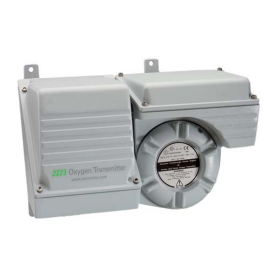
Summary of Contents for Servomex 2223A
- Page 1 SERVOTOUGH OxyExact 2223A Transmitter Functional Safety Manual Part Number: 02223006A Revision: Language: UK English...
- Page 2 This page intentionally blank.
-
Page 3: Table Of Contents
2223A Oxygen Transmitter Functional Safety Manual LIST OF CONTENTS Section INTRODUCTION ....................1 Purpose of this manual ..................1 Product description ..................... 1 Required documentation..................1 DEFINITIONS AND DESCRIPTIONS ..............3 Safety instrumented system (SIS) ..............3 Safety function ....................3 Safe failure...................... - Page 4 2223A Oxygen Transmitter Functional Safety Manual This page intentionally blank. 02223006A / Revision 0...
-
Page 5: Introduction
Additional status indications are provided by further solid state relays. The 2223A Oxygen Transmitter is normally used in conjunction with a 2210 or 2213 Control Unit. This provides additional system inputs and outputs and allows the transmitter to be configured and measurements to be displayed. - Page 6 2223A Oxygen Transmitter Functional Safety Manual This page intentionally blank. 02223006A / Revision 0...
-
Page 7: Definitions And Descriptions
2223A Oxygen Transmitter Functional Safety Manual DEFINITIONS AND DESCRIPTIONS Safety instrumented system (SIS) A safety instrumented system comprises components and subsystems (from sensor through to final element) which provide functions aimed at mitigating dangerous failure conditions. Safety function A defined function executed by a safety instrumented system which is intended to mitigate a specific dangerous event. -
Page 8: Hardware Fault Tolerance (Hft)
2223A Oxygen Transmitter Functional Safety Manual Hardware fault tolerance (HFT) The ability to continue to provide a safety function in the presence of faults and errors. A hardware fault tolerance of N means that N+1 faults could cause the loss of a safety function. -
Page 9: Safety Integrity Level (Sil)
2223A Oxygen Transmitter Functional Safety Manual 2.12 Safety integrity level (SIL) The international standard IEC 61508 defines four Safety Integrity Levels from SIL1 to SIL4. Each of these corresponds to a range of probabilities that the safety function will fail. - Page 10 2223A Oxygen Transmitter Functional Safety Manual This page intentionally blank. 02223006A / Revision 0...
-
Page 11: Safety Instructions
2223A Oxygen Transmitter Functional Safety Manual SAFETY INSTRUCTIONS Boundary of safety system The following aspects of the 2223A Oxygen Transmitter are considered to be within the boundary of the safety system covered in this manual: • Paramagnetic cell • All signal processing and support functions. This includes optional pressure compensation and flow alarm when fitted and enabled. -
Page 12: Settings
2223A Oxygen Transmitter Functional Safety Manual Settings After installation and commissioning according to the installation manual, the following settings should be made to support the safety function. This will require the use of a 2210 or 2213 Control Unit or a 2215 Tx Interface. To access these functions press the Enter key, navigate to →... -
Page 13: Fault Relay
2223A Oxygen Transmitter Functional Safety Manual 3.4.2 Fault relay Select the Fault Relay and configure as follows. 3.4.3 Flow alarm If the internal flow alarm is fitted and enabled, it should be calibrated at “normal” gas flow as described in the operator manual. Alarm levels should then be set as appropriate. -
Page 14: Protection Of Settings
If there are any transmitter fault conditions present, these must be resolved before proceeding. It is also recommended that any maintenance-required conditions are addressed. For all tests it is assumed that the 2223A Oxygen Transmitter is powered and has reached stable operating temperature. 3.6.1 Checks where pressure compensation is not used. -
Page 15: Checks Where Pressure Compensation Is Used
2223A Oxygen Transmitter Functional Safety Manual 3.6.2 Checks where pressure compensation is used. Take appropriate action to ensure that spurious outputs will not compromise safety or cause false trips. Using the built-in analog output test feature, set the output to 0.0mA and verify that the correct current is generated. - Page 16 2223A Oxygen Transmitter Functional Safety Manual This page intentionally blank. 02223006A / Revision 0...
-
Page 17: A1 Appendix
2223A Oxygen Transmitter Functional Safety Manual APPENDIX 02223006A / Revision 0...


Need help?
Do you have a question about the 2223A and is the answer not in the manual?
Questions and answers