Table of Contents
Advertisement
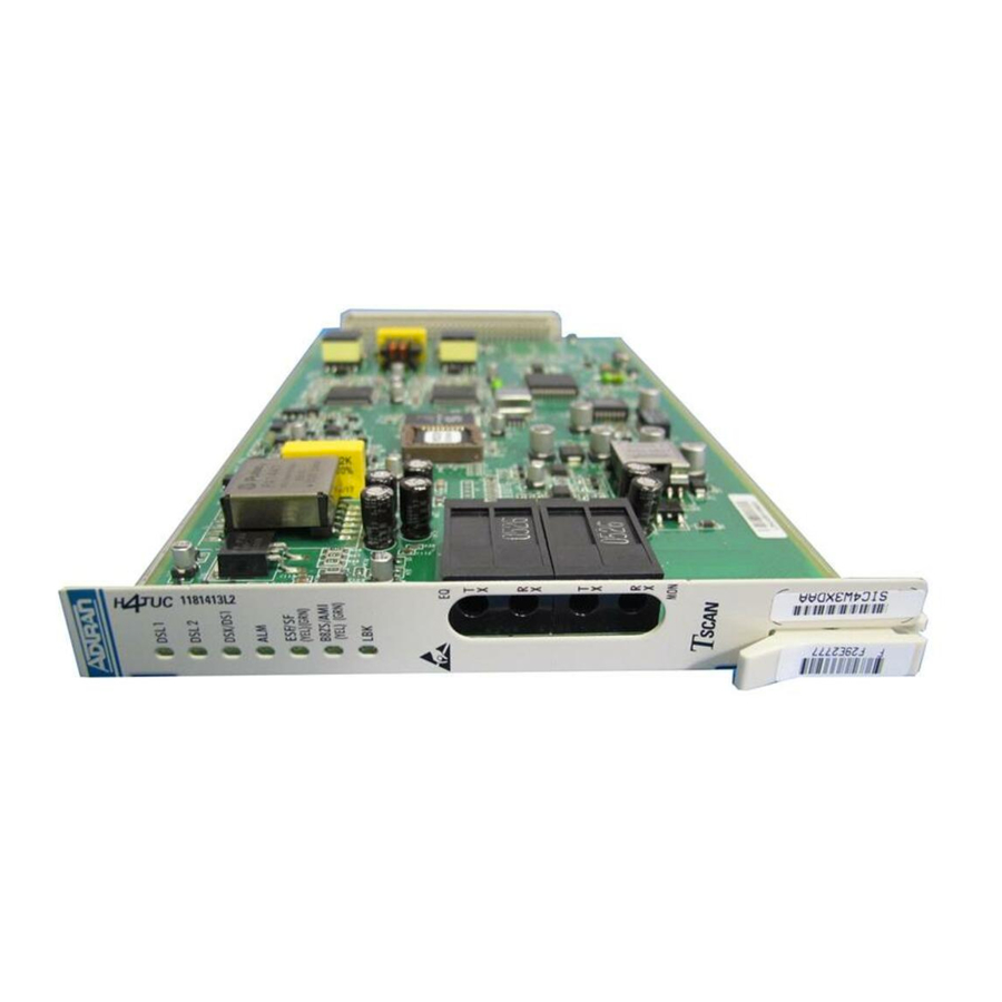
DSL 1
DSL 2
DSX/DS1
ALM
ESF/ SF
(YEL) (GRN)
B8ZS/AMI
(YEL) (GRN)
LBK
EQ
T
DSX-1
X
R
X
T
X
R
X
MON
HDSL4 for General Distribution
Installation and Maintenance Practice
Document Number: 61223HDSL4L2-5C
August 2005
Total Access 3000 H4TU-C
220 H4TU-C
DDM+ H4TU-C
3192 H4TU-C
3192M H4TU-C
T200 H4TU-C
T200 H4TU-R, Local Powered
T200 H4TU-R, Span Powered
239 H4R
1223445L1
HDSL4
LP1
NET
LP2
LP1
CUST
LP2
LL RL
/
(Y) (G)
®
1181413L2
1223401L2
1223403L2
1223404L2
1223404L12
1223406L2
1223424L2
1223426L2
239 H4R
1223445L1
LP1
NET
LP2
LP1
CUST
LP2
LL RL
/
TX
(Y) (G)
M
O
N
RX
R
S
2
3
2
SIC4W3XD_ _
T1L8PNMC_ _
T1L8VOSC_ _
T1L8YHWC_ _
T1L9EFGA_ _
T1T2JE0B_ _
T1L497PC_ _
T1L85M7C_ _
1223426L2
DSL 1
DSL 2
DS1
ALM
ESF/SF
(YEL)
(GRN)
B8ZS/AMI
(YEL)
(GRN)
LLB/RLB
(YEL)
(GRN)
DS1
LOC
LBK
REM
Advertisement
Table of Contents
Troubleshooting

Related Manuals for ADTRAN HDSL4


Summary of Contents for ADTRAN HDSL4
- Page 1 DSL 1 DSL 2 DSX/DS1 ESF/ SF (YEL) (GRN) B8ZS/AMI (YEL) (GRN) DSX-1 ® HDSL4 for General Distribution Installation and Maintenance Practice Document Number: 61223HDSL4L2-5C August 2005 Total Access 3000 H4TU-C 220 H4TU-C DDM+ H4TU-C 3192 H4TU-C 3192M H4TU-C T200 H4TU-C...
- Page 2 In no event will ADTRAN be liable for any special, incidental, or consequential damages or for commercial losses even if ADTRAN has been advised thereof as a result of issue of this publi- cation.
-
Page 3: Revision History
HDSL4 for General Distribution Installation and Maintenance Practice Revision History Revision Date November 2004 June 2005 August 2005 Conventions The following typographical conventions are used in this document: This font indicates a cross-reference link. First-time references to tables and figures are... - Page 4 Training ADTRAN offers training courses on our products. These courses include overviews on product features and functions while covering applications of ADTRAN’s product lines. ADTRAN provides a variety of training options, including customized training and courses taught at our facilities or at customer sites.
-
Page 5: Table Of Contents
Accessing the HDSL4 Main Menu (Total Access 3000 H4TU-C) ....... . - Page 6 HDSL4 Facility Alarm History ........
- Page 7 ADTRAN Technical Support ........
- Page 8 HDSL4 Facility Alarm History Screen ........
- Page 9 HDSL4 Circuit Segments ........
- Page 10 HDSL4 Loopback Control Codes ........
-
Page 11: Product Description
HDSL4 for General Distribution PRODUCT DESCRIPTION The HDSL4 modules referenced in this document are used to deploy a T1 circuit using 4-wire metallic facilities. HDSL4 provides extended range to DS1/T1 transport while providing spectral compatibility with ADSL and other transport technologies. The ADTRAN HDSL4 Transceiver Unit for Central Office (H4TU-C) works in conjunction with the ADTRAN HDSL4 Remote Transceiver Unit (H4TU-R) to provide extended-range DS1 service on the local loop. -
Page 12: Illustrations
Product Description Illustrations Figure 1 illustrates the front panels of the ADTRAN H4TU-C modules approved for general distribution. 1223401L2 DSL 1 DSL 2 DSX/DS1 ESF/ SF (YEL) (GRN) B8ZS/AMI (YEL) (GRN) Total Access 3000 220 H4TU-C H4TU-C P/N 1223401L2 P/N 1181413L2 Figure 1. -
Page 13: Figure 2. Adtran Hdsl4 Remote Units For General Distribution
1. In all applications the H4TU-C must be installed in NEBS compliant and UL listed enclosures to insure full compliance with this unit. 2. The ADTRAN T200 Dual-Mount housing (P/N 1245034L1) is required when using the T200 H2TU-C for HDSL Loop Support System (HLSS™) protection circuits. -
Page 14: Compliance
Product Description Compliance ADTRAN HDSL4 modules are NRTL listed to the applicable UL standards. The HDSL4 modules are to be installed in a restricted access location and in a type “B” or “E” enclosure only. These devices comply with Part 15 of the FCC rules. Operation is subject to the following two conditions: 1. -
Page 15: Installation Guidelines
HDSL4 for General Distribution Installation and Maintenance Practice INSTALLATION GUIDELINES After unpacking an HDSL4 module, inspect it for damage. If damage has occurred, file a claim with the carrier, then contact ADTRAN Customer Service. For more information, refer to “Appendix D, Warranty”. -
Page 16: H4Tu-R Span Power
Installation Guidelines Disabling the span power removes all voltage from the HDSL4 loop. This results in an absence of sealing current which could have an adverse effect on circuit continuity over an extended period of time. The H4TU-C uses a DC-to-DC converter to derive its internal logic and span powering voltages from the –48 VDC office supply. -
Page 17: Module Installation
5. Secure the module in place by pushing in on the ejector latch. All Other Modules To install any of the HDSL4 modules, with the exception of those explained above, perform the following steps: 1. Hold the unit by the front panel while supporting the bottom edge of the module and engage the enclosure edge. -
Page 18: Edge Connector Wiring
DSX-1 Tx Out Ring (Wire-Wrap) 220 Edge Connector Wiring Figure 4. 220 and DDM+ H4TU-C Edge Connector Wiring HDSL4 for General Distribution Installation and Maintenance Practice specify edge connection wiring required for proper -48 VDC (1) LP1 Tip LP1 Ring... -
Page 19: Figure 5. 3192M, 3192, T200 H4Tu-C And T200 H4Tu-R Edge Connector Wiring
HDSL4 for General Distribution Installation and Maintenance Practice R Tx DSX (In from DSX) R1 Rx DSX (Out to DSX) -48 VDC Return R1 HDSL4 Loop 2 -48 VDC R HDSL4 Loop 1 Fuse Alarm (to Alarm Module) T Tx DSX (In from DSX) -
Page 20: Total Access 3000 H4Tu-C Edge Connector
The Total Access 3000 shelf delivers DSX-1 from the network to the H4TU-C via connectors on the backplane labeled “Pair 7” and “Pair 8”. The HDSL4 signal is provided toward the customer via the backplane connectors labeled “Pair 1” and “Pair 2”. Pins 1 and 33 of the connectors Pair 7 and Pair 8 are the DSX connections for the H4TU-C in Slot 1. -
Page 21: Provisioning
HDSL4 for General Distribution Installation and Maintenance Practice PROVISIONING HDSL4 Configuration is performed via software control. For more information, refer to the “Control Port Operation” section of this practice. Provisioning Options The provisioning settings can be viewed and manipulated through access to the firmware via the front panel RS-232 port. - Page 22 3192M H4TU-C (P/N 1223404L12) and 3192 H4TU-C (P/N 1223404L2) only. The Span Power option is available on H4TU-C units only. The Shelf Alarm option is available on DDM+, 3192M, and 3192 H4TU-C units only. HDSL4 for General Distribution Installation and Maintenance Practice Option Settings Disabled, Enabled Disabled, Enabled...
-
Page 23: Provisioning Options, Total Access 3000 H4Tu-C
EQ jack setting on the loopback/test screen. HDSL4 SYSTEM TESTING The ADTRAN HDSL4 system provides the ability to monitor the status and performance of the DSX-1 signals, DS1 signals, and HDSL4 loop signals. Detailed performance monitoring is provided by the front panel-mounted RS-232 control port. -
Page 24: H4Tu-R Bantam Jacks
H4TU-R module and the network. Figure 7 illustrates the complete bantam jack arrangement and details for specific jacks. HDSL4 for General Distribution Installation and Maintenance Practice jacks. (Test access toward the network equipment is MON RX jack, and the input (REC) of the Access”. -
Page 25: Loopbacks
3. H4TU-R modules respond to loopbacks initiated using front panel pushbuttons. ADTRAN HDSL4 modules contain smartloop technology. By constantly monitoring the DSX-1 for a framing pattern, ADTRAN HDSL4 modules initiate the proper loopback regardless of how the loopback control sequence is sent (framed or unframed). -
Page 26: Figure 8. Hdsl4 Loopbacks
HDSL4 System Testing The loopback condition imposed in both cases is a logic level loopback at the point within an H4TU-C module where the DSX-1 signal passes into the HDSL4 modulators. all of the loopback locations possible with ADTRAN HDSL4 equipment. -
Page 27: H4Tu-R Front Panel Pushbuttons
H4TU-R and network). If the loopback is active, pressing the pushbutton a second time disables the loopback. Front Panel LED Indicators LED indicators mounted on the front panel of the unit provide status of the HDSL4 circuit. Each indicator is described in Table 8. H4TU-C Front Panel LED Indicators... -
Page 28: Table 9. H4Tu-R Front Panel Led Indicators
Unit is provisioned for B8ZS line code data Green Unit is provisioned for AMI line code data Unit is not in loopback Yellow Unit is in loopback (network and/or customer) Green H4TU-C is in loopback toward the HDSL4 for Verizon 61223HDSL4L2-5C... -
Page 29: Control Port Operation
The Total Access 3000 H4TU-C Control Port access is provided via the DB-9 connector on the Total Access System Controller Unit (SCU), P/N 1181018Lx. This section provides Total Access 3000 H4TU-C screens separately where they differ from other HDSL4 screens. When the ADC HiGain® Management Unit (HMU) is installed, the 3192M DB-9 is disabled. -
Page 30: Menu Structure
Menu Structure The menu structure for the HDSL4 products is a layered menu. Each menu level consists of submenus and/or menu items. • Submenus are elements that move the display down to the next menu level. -
Page 31: Figure 10. Adtran Hdsl4 Main Menu
HDSL4 for General Distribution Installation and Maintenance Practice Circuit ID:HNTSVLALHDSL4 Figure 10. ADTRAN HDSL4 Main Menu To display a particular screen from the menu, press the number key associated with the screen title, and then press the The menu options are as follows: •... -
Page 32: Accessing The Hdsl4 Main Menu (Total Access 3000 H4Tu-C)
Control Port Operation Accessing the HDSL4 Main Menu (Total Access 3000 H4TU-C) Accessing the HDSL4 circuit information via the Total Access 3000 System Controller Unit (SCU) control port requires a successful logon with a recognized account name and password. Figure 11. -
Page 33: Access Module Menus
14 - ... [None] Figure 13. Access Module Menus Screen HDSL4 Main Menu (Total Access 3000 H4TU-C) The HDSL4 Main Menu provides access to detailed performance and configuration infor- mation. The Operation, Administration, Maintenance, and Provisioning (OAM&P) screens are available as listed on... -
Page 34: Hdsl4 Unit Information
“Flash Upgrade” on page 50 HDSL4 Unit Information The Unit Information screen component in the HDSL4 circuit. ADTRAN Technical Support contact numbers are also available from the Unit Information screen. Circuit ID:HNTSVLALHDSL4 --------------------- For Information or Technical Support -------------------- Support Hours ( Normal 7am - 7pm CST, Emergency 7 days x 24 hours ) Phone: 800.726.8663 / 888.873.HDSL... -
Page 35: Provisioning
HDSL4 for General Distribution Installation and Maintenance Practice Provisioning The Provisioning menu displays current settings. Depending on the selected product, one of two Provisioning menus displays: • “Provisioning Menu” on page 25 • “Provisioning Menu (Total Access 3000 H4TU-C)” Provisioning Menu... -
Page 36: Provisioning Menu (Total Access 3000 H4Tu-C)
Shelf: Slot: Unacknowledged Alarms: Figure 18. Total Access 3000 H4TU-C Provisioning Screen 2 To re-deploy this unit, press Table 6 Table HDSL4 for General Distribution Installation and Maintenance Practice and press NTER , and press NTER Total Access System INFO... -
Page 37: Span Status
HDSL4 for General Distribution Installation and Maintenance Practice Span Status The Span Status Screen provides quick access to status information for each HDSL4 receiver in the circuit. Depending on the selected product, one of two Span Status Screens displays: •... -
Page 38: Span Status Screen (Total Access 3000 H4Tu-C)
The menu options are as follows: • “View Detailed Status” on page 29 • “View Auto In Service Status” HDSL4 for General Distribution Installation and Maintenance Practice Total Access System MAJOR INFO Circuit ID: Span Status Screen ______... -
Page 39: View Detailed Status
HDSL4 for General Distribution Installation and Maintenance Practice View Detailed Status The View Detailed Status selection from the Span Status Screen menu the HDSL4 status for each receiver point. Circuit ID:HNTSVLALHDSL4 MARGIN Interface (CUR/MIN/MAX) (CUR/MAX) --------- ------------- --------- H4TUC 17/00/17... -
Page 40: Table 10. Auto In Service Status Indications
A link is provided to view the Alarm History Screen. The Alarm History Screen screen is also available by selecting the HDSL4 Main Menu opti System responses displayed in the status fields on the Alarm History Screen are shown in Table Table 10. -
Page 41: Loopbacks And Test
HDSL4 for General Distribution Installation and Maintenance Practice Loopbacks and Test The Loopback and Test Commands menu is used to evoke or terminate all available HDSL4 loopbacks. Each HDSL4 circuit component can be looped toward the network or customer from this screen. Unit self tests can also be initiated from this screen. When any loopback is active, a “Loop Down ALL Units”... -
Page 42: Loopback And Test Commands Menu (Total Access 3000 H4Tu-C)
• Equipment Jack selection - Select Network or Customer for testing purposes. Refer to “Appendix C, Front Panel DSX and MUX Mode Test Access” • Bit Error Rate Testing (BERT). HDSL4 for General Distribution Installation and Maintenance Practice Total Access System MAJOR... -
Page 43: Bert Test Functions
HDSL4 for General Distribution Installation and Maintenance Practice BERT Test Functions When selecting the BERT Test Functions option from the Loopbacks and Test Commands menu, the BERT Test Screen displays Shelf: Slot: Unacknowledged Alarms: ----------------------------------------------------- Test Direction: Unframed Pattern Generation: OFF... -
Page 44: Select Data Pattern
00:00, per the note on the screen. Shelf: Slot: Unacknowledged Alarms: Figure 27. BERT Test Functions - Selection 4, Enter Test Time Out HDSL4 for General Distribution Installation and Maintenance Practice Figure 26 illustrates this screen with the menu Total Access System MAJOR... -
Page 45: Toggle Test Direction
HDSL4 for General Distribution Installation and Maintenance Practice Toggle Test Direction With no test running, the Toggle Test Direction option on the BERT Test Screen allows changing (toggling) the test signal in the opposite direction (from customer to network and vice versa). -
Page 46: Performance History
Abbreviations used in the Performance Monitoring screens are defined in the Data Definitions screens (Figure 30 Figure HDSL4 for General Distribution Installation and Maintenance Practice (Figure 29) displays the historical HDSL4 and T1 performance Press ESC to return to previous menu... -
Page 47: Figure 30. Performance Data Definitions, Loop
HDSL4 for General Distribution Installation and Maintenance Practice Circuit ID:HNTSVLALHDSL4 H4TUC, H4TUR, and H4R LOOP Related: ES-L Errored Seconds SES-L Severely Errored Seconds UAS-L Unavailable Seconds DS1 and DSX-1 Line Related: ES-L Errored Seconds SES-L Severely Errored Seconds UAS-L Unavailable Seconds... -
Page 48: Scratch Pad, Circuit Id And Date/Time Screen
New Scratch Pad = New Circuit ID = HNTSVLALHDSL4 New Date = New Time = Figure 32. Scratch Pad, Circuit ID, and Date/Time Screen HDSL4 for General Distribution Installation and Maintenance Practice (Figure NOTE Press ESC to return to previous menu (MM/DD/YY) (HH:MM:SS) Press TAB to skip to next entry field. -
Page 49: Terminal Modes
• Real-Time Update Mode (VT100) - This mode provides real-time updating of HDSL4 circuit conditions and provisioning options as changes occur. The default mode is Real-Time Update. -
Page 50: Alarm History
-------------------------------------------------------------------------------- T1 Alarm Facility Alarm Span H4TUC to H4R1 Figure 34. T1 Alarm History Screen HDSL4 for General Distribution Installation and Maintenance Practice on page 41 (Figure 34) displays the following information: Press ESC to return to previous menu T1 Alarm History... -
Page 51: Hdsl4 Facility Alarm History
HDSL4 for General Distribution Installation and Maintenance Practice HDSL4 Facility Alarm History The HDSL4 Facility Alarm History screen • DC Open • Over-current (short) • Ground fault • Power cycle Circuit ID:HNTSVLALHDSL4 LOCATION ALARM -------------------------------------------------------------------------------- FACILITY DC OPEN FACILITY SHORT... -
Page 52: Hdsl4 Span History
Control Port Operation HDSL4 Span History The HDSL4 Span History screen • Loss of Sync for each HDSL4 receiver • Margin Threshold Alarm for each HDSL4 receiver • Attenuation Threshold Alarm for each HDSL4 receiver Circuit ID:HNTSVLALHDSL4 LOCATION ALARM --------------------------------------------------------------------------------... -
Page 53: Event History
• Event Log Reset • External Alarm Blocking Change • Framing Option Change • H4TU-C/H4TU-R Powered Up 61223HDSL4L2-5C 37) provides a log history of HDSL4 circuit events. Press ESC to return to previous menu Date 01/01/00 00:00:01 01/01/00 00:03:08 01/01/00 00:00:01... -
Page 54: The System Pm/Screen Report
Figure 38. System PM/Screen Report Option Clear PM and Alarm Histories The Clear PM and Alarm Histories option from the HDSL4 Main Menu initializes data from performance monitoring and alarm histories. Selecting this option from the Main Menu displays the prompt shown in... -
Page 55: Troubleshooting
ADTRAN contact information appear on this screen. Circuit ID: For HELP based on detected problems, select Troubleshooting Guidance from the list below. If further assistance is needed, contact ADTRAN Tech Support. Hours: Normal 7am - 7pm CST Emergency 7 days x 24 hours Phone: 800.726.8663 / 888.873.HDSL... -
Page 56: General Information
Attenuation (1st Segment) H4TUC <= 31 dB, H4TUR/H4R <= 33 dB Attenuation (2nd or 3rd Segment) H4TUR/H4R <= 30 dB Figure 42. General Information Screen HDSL4 for General Distribution Installation and Maintenance Practice Press ESC to return to previous menu DSX-1 Loss of Signal (Red Alarm) -
Page 57: Chronic Circuit Guidance
43). This screen provides general information about circuits with bad splice connec- tions as well as a menu to the Bad Splice Detection feature. Splices that are varying in impedance cause the HDSL transceiver to see a reduced and/or fluctuating signal quality (margin). The HDSL transceiver attempts to track these changes, but when the changes become too severe, errors or loss of synchronization result. -
Page 58: View Splice Results
---------- H4TUC H4TUR H4RU1 NET H4RU1 CST Figure 44. View Splice Results Screen HDSL4 for General Distribution Installation and Maintenance Practice (Figure 44) to display test results for each transceiver. Press ESC to return to previous menu Version Loop 2... -
Page 59: View Histogram Screen
• Column 2 indicates the respective transceiver that has reported the anomaly. The L1 and L2 columns represent Loop 1 and Loop 2 of the HDSL4 circuit. • Column 3 displays the count registered by the H4TU-R, also with Loop 1 and Loop 2 counts. -
Page 60: Flash Upgrade
• “Download HTUC via Y-Modem” • “Download HTUC via TFTP” • “Boot Block Status” on page 53 HDSL4 for General Distribution Installation and Maintenance Practice NOTE Total Access System INFO Circuit ID:HntsvlALMn0103 Main SW Ver Boot SW Ver HTUC Flash Image:... -
Page 61: Figure 48. Download Via Y-Modem, In Progress
HDSL4 for General Distribution Installation and Maintenance Practice Download HTUC via Y-Modem The Download H4TU-C via Y-Modem screen transfer from the computer connected to the SCU craft access port to the H4TU-C. This file is transferred to the SCU and downloaded to the H4TU-C at the SCU craft port baud rate;... -
Page 62: Figure 49. Download H4Tu-C Via Tftp
This utility programs the H4TUC. address of the TFTP server that has the firmware binary file (*.bin). Figure 49. Download H4TU-C via TFTP HDSL4 for General Distribution Installation and Maintenance Practice (Figure 49) is utilized to perform a TFTP file transfer... -
Page 63: Figure 50. Boot Block Status Screen
HDSL4 for General Distribution Installation and Maintenance Practice Boot Block Status The Boot Block Status screen in rare cases can become locked. If locked, the bootcode cannot be upgraded by future firmware upgrades. The bootcode is seldom changed with new download code. -
Page 64: Figure 51. Virtual Terminal Control Screen
This option is not a function of the Total Access 3000 H4TU-C. Circuit ID:HNTSVLALHDSL4 Figure 51. Virtual Terminal Control Screen HDSL4 for General Distribution Installation and Maintenance Practice (Figure 51) allows control of remote unit provisioning option from this screen, and press... -
Page 65: Figure 52. Hdsl4 Circuit Segments
The ADTRAN HDSL4 system provides DS1-based services over loops designed to comply with the guidelines given below. These guidelines apply to a single segment circuit (an HDSL4 circuit with no H4Rs), to a circuit having two segments (with one H4R), or to a circuit having 3 or 4 segments (with two or three H4Rs). -
Page 66: Range Limits
Range Limits Table 12 Table 13 provide the maximum ranges for HDSL4 segments per wire gauge. • Recommended Design Limits indicates the recommended range limitation • Recommended Turn-up Limits indicates the absolute maximum range In three segment circuits (two H4Rs), individual segment resis- tance values must be verified. -
Page 67: Resistance Values
HDSL4 for General Distribution Installation and Maintenance Practice Resistance Values Span Powering Two Repeaters with Span Powered Remote Each of the three segments associated with span powering two H4Rs and a H4TU-R must satisfy the DC resistance budgets in addition to the recommended loop attenuation require- ments. -
Page 68: Figure 53. Resistance Budget, Span Powering Two Repeaters
1). If the instance where these two points is above this line, the H4TU-C cannot span power two H4Rs and the H4TU-R. These measurements represent only one of the two HDSL4 pairs. WITHIN LIMITS Figure 53. Resistance Budget, Span Powering Two Repeaters... -
Page 69: Figure 54. Resistance Budget, Span Powering Two Repeaters (Example)
HDSL4 for General Distribution Installation and Maintenance Practice An example problem is illustrated in measurements: • 600 ohm first segment resistance • 700 ohm second segment resistance • 900 ohm third segment resistance Refer to the graph, follow these steps to solve the example problem: 1. -
Page 70: Span Powering Three Repeaters
HDSL4 Deployment Guidelines Span Powering Three Repeaters An ADTRAN HDSL4 circuit can power three elements only. If three repeaters are utilized in the circuit, the locally powered H4TU-R (P/N 1223424L2, CLEI T1L83Z3C_ _ or later) must be utilized. HDSL4 circuits utilizing three repeaters have different resistance budget requirements. -
Page 71: Maintenance
Figure 55. Resistance Budget, Span Powering Three Repeaters MAINTENANCE The HDSL4 products detailed in this document do not require routine maintenance. In case of equipment malfunction, use the front panel bantam jack connectors to help locate the source of the problem. -
Page 72: H4Tu-C Troubleshooting
LED indicators. 4. If steps pass, but step The HDSL4 Loop has poor signal quality or loss of sync on the loop indicated by the LED. Basic troubleshooting procedures should iden- tify a problem with the cable pair. -
Page 73: Table 17. H4Tu-C Product Specifications
HDSL4 for General Distribution Installation and Maintenance Practice Table 17. H4TU-C Product Specifications Specification H4TU-C Tx Pwr (Data) Level: H4TU-C Tx Pwr (Activation) Level: Maximum Loop Resistance: DSX-1 Line Build Out: DS1 Framing Format: Tested with the ADTRAN H4TU-R (1223426L2) - Page 74 Total Access 3000 H4TU-C: Temperature, Operating: Temperature, Storage: NRTL Listed to the applicable UL standards Total Access 3000 H4TU-C: HDSL4 for General Distribution Installation and Maintenance Practice Clock Clock Sources: DSX-1 Derived (with HDSL4 frame bit stuffing) ± 25 ppm (exceeds Stratum 4); meets T1.101...
-
Page 75: Table 18. H4Tu-R Product Specifications
HDSL4 for General Distribution Installation and Maintenance Practice Table 18 lists the product specifications for each H4TU-R included in this practice. Table 18. H4TU-R Product Specifications Specification H4TU-C Tx Pwr (Data) Level: H4TU-C Tx Pwr (Activation) Level: Maximum Loop Resistance:... - Page 76 Dimensions: T200 H4TU-R: Temperature, Operating: Temperature, Storage: NRTL Listed to the applicable UL standards T200 H4TU-R, Local Powered: T200 H4TU-R, Span Powered: HDSL4 for General Distribution Installation and Maintenance Practice Tests Diagnostics: Self Test Loopback (H4TU-R) initiated with T1 NIU in-band codes...
-
Page 77: Loopback, Control Codes, And Commands
Upon deactivation of a loopback, the HDSL4 system will synchronize automatically. Loopback Process Description In general, the loopback process for the HDSL4 system elements is modeled on the corre- sponding DS1 system process. Specifically, the H4TU-C loopback is similar to an Intelligent Office Repeater loopback, and the H4TU-R loopbacks are similar to an in-line T1 Repeater loopback. -
Page 78: Table A-1. Hdsl4 Loopback Control Codes
2. All codes are in-band unless labeled ESF-DL. 3. All codes listed above must be sent for a minimum of 5 seconds to be detected and acted upon. HDSL4 for General Distribution Installation and Maintenance Practice Name Loopback data from network toward network in... -
Page 79: Table A-2. Loopback Control Codes
HDSL4 for General Distribution Installation and Maintenance Practice Table A-2. Loopback Control Codes Function Code (Hex / Binary) ARM (in-band) - also 11000 (binary) known as 2-in-5 pattern ARM (ESF Data FF48 or Link) 1111 1111 0100 1000 sent in the Facility Data... - Page 80 Second H4R C754 1100 0111 0101 0100 Loopback HDSL4 for General Distribution Installation and Maintenance Practice Response If the units are armed or a unit is currently in loop- back when this pattern is sent from the network, the loopback time out is disabled. As long as the units remain armed, the time out remains dis- abled.
- Page 81 HDSL4 for General Distribution Installation and Maintenance Practice Table A-2. Loopback Control Codes (Continued) Function Code (Hex / Binary) Third H4R C743 1100 0111 0100 0011 Loopback H4TU-R Address 20 C742 for Extended 1100 0111 0100 0010 Demarc 1. All codes listed above must be sent for a minimum of 5 seconds to be detected and acted upon.
- Page 82 HDSL4 Maintenance Modes HDSL4 for General Distribution Installation and Maintenance Practice This page is intentionally blank. 61223HDSL4L2-5C...
-
Page 83: Hdsl4 Features
HDSL4 Features HDSL NEW ENHANCED FEATURE OVERVIEW The new HDSL2 and HDSL4 products contain new features to enhance their performance and help the customer reduce down time. Each new feature is listed and briefly described below.: • “TScan” on page B-2 •... -
Page 84: Tscan
• Remote detection of the presence or absence of a ground connection in the remote mount. TScan allows operators to integrate these capabilities across multiple computing platforms with existing operating systems. Figure B-1. TScan Diagnostic Capabilities For implementation of TScan please contact an ADTRAN sales representative. HDSL4 for General Distribution Installation and Maintenance Practice Figure... -
Page 85: Bad Splice Detection
In data mode, the detector will run periodically after synchronization is achieved. The HDSL4 transceiver monitors the loop for impedance changes that are of a magnitude to cause the received signal of the transceiver to be degraded. When a significant impedance change is detected by the transceiver, the approximate distance from that transceiver to the anomaly is recorded on the Splice Histogram screen by incrementing the appropriate counter. -
Page 86: Screen Support
“Bad Splice Detected” is made on the first detection occurrence seen since the last splice detection reset. This entry serves to alert the technician that a trouble has been detected without filling up the event log. HDSL4 for General Distribution Installation and Maintenance Practice 61223HDSL4L2-5C... -
Page 87: Splice Detection Screens
HDSL4 for General Distribution Installation and Maintenance Practice Splice Detection Screens Chronic Circuit Problems The Chronic Circuit Problems screen with bad splices. Field experience has shown that many chronic circuit failures are due to bad splices. These type circuits generally have the following symptoms: - Wire pairs pass all electrical tests and meet deployment guidelines. -
Page 88: Figure B-3. Splice Results Screen
The number shown in this column represents the number of feet from the transceiver (Reference Point) to that anomaly. This number will also reflect the highest anomaly count seen, as it is possible to have more than one bad splice per circuit. -
Page 89: View Splice Histogram
• Column 2 indicates the respective transceiver that has reported the anomaly. The L1 and L2 columns represent Loop 1 and Loop 2 of the HDSL4 circuit. • Column 3 displays the count registered by the H4TU-R, also with Loop 1 and Loop 2 counts. -
Page 90: Figure B-5. Event History Screen
Splice detection support is not available for two-wire repeaters. HDSL4 for General Distribution Installation and Maintenance Practice B-5) shows the messages reported in the event log due to the... -
Page 91: Using The Bad Splice Detector
HDSL4 for General Distribution Installation and Maintenance Practice Using the Bad Splice Detector A brief synopsis of steps that might be utilized on a trouble analysis are as follows: 1. Check the HDSL units for margin fluctuation by checking the Min & Max margins on the Detailed Span Status screen (differ by >... -
Page 92: Fault (Gfi, Short) Bridging
• brief power fault incidents (lightning) • brief signal distortions. In the older generation HDSL4 transceivers, a brief short or GFI would cause a hardware control to quickly shut down the span power supply for safety reasons. The software would then detect the power fault and would hold the span supply off for 3 seconds. -
Page 93: Fast Retrain Feature
HDSL4 for General Distribution Installation and Maintenance Practice Fast Retrain Feature Fast Retrain is an ADTRAN proprietary feature whose intent is to minimize downtime when an intermittent non power-related impairment (bad splice, noise burst, etc.) affects the HDSL loop and cannot be bridged. - Page 94 HDSL NEW ENHANCED FEATURE OVERVIEW HDSL4 for General Distribution Installation and Maintenance Practice This page is intentionally blank. B-12 61223HDSL4L2-5C...
-
Page 95: Figure C-1. Dsx Mon, Tx To Customer
Front Panel DSX and MUX Mode Test Access GENERAL Figure C-1 through Figure C-3 Figure C-7 are MUX fed modes of operation. From the Provisioning menu 25), Network Source is used to choose either MUX fed or DSX fed. When performing intrusive MUX mode testing, the equipment jack on the front panel can be configured to access the signal going to the Network or the Customer. -
Page 96: Figure C-3. Dsx Eq, Tx To Customer, Rx From Customer
This test is intrusive, as it connects the from the customer data. T1 BERT Figure C-3. DSX EQ, Tx to Customer, Rx from Customer HDSL4 for General Distribution Installation and Maintenance Practice jack (Figure RX MON 432 Ω... -
Page 97: Figure C-5. Mux Mon, Rx From Customer
HDSL4 for General Distribution Installation and Maintenance Practice MUX MODE TEST ACCESS MUX MON, Tx to Customer The Rx of the BERT receives data from the the data that the H4TU-C will transmit to the customer. The Tx of the BERT is not used. This test is non-intrusive. -
Page 98: Figure C-7. Mux Eq, Tx To Customer, Rx From Customer
To Customer mode, AIS (unframed all 1’s) is sent in the network direction. T1 BERT Figure C-7. MUX EQ, Tx to Customer, Rx from Customer HDSL4 for General Distribution Installation and Maintenance Practice jack, and the Rx of the BERT is connected to the EQ TX... -
Page 99: Warranty
Appendix D Warranty WARRANTY AND CUSTOMER SERVICE ADTRAN will replace or repair this product within the warranty period if it does not meet its published specifications or fails while in service. Warranty information can be found at www.adtran.com/warranty. Refer to the following subsections for sales, support, Customer and Product Service (CAPS) requests, or further information. - Page 100 ® Carrier Networks Division 901 Explorer Blvd. Huntsville, AL 35806...
Need help?
Do you have a question about the HDSL4 and is the answer not in the manual?
Questions and answers