Table of Contents
Advertisement
Advertisement
Chapters
Table of Contents

Related Manuals for Germfree LFGI-3USP

Summary of Contents for Germfree LFGI-3USP
- Page 1 Laminar Flow LFGI (CAI or CACI) User Manual...
- Page 2 © GERMFREE 11 Aviator Way Ormond Beach, FL 32174 800-888-5357 Phone 386-677-1114 Fax Info@Germfree.com www.Germfree.com...
-
Page 3: Table Of Contents
Table of Contents PREFACE AFETY PERATION AND DDITIONAL ROFESSIONAL RAINING GERMFREE, LFGI USP <797> INTRODUCTION RODUCT ROTECTION ERSONNEL ROTECTION ARTICULATES AND ASES APORS THEORY HEPA F ILTRATION NIDIRECTIONAL AMINAR RESSURIZATION ONTAINMENT UNPACKING INSTRUCTIONS INSTALLATION ELECTRICAL REQUIREMENTS CERTIFICATION PARTS IDENTIFIER LFGI... - Page 4 LFGI- H LEANING THE EAVY IGOROUS LFGI UTSIDE THE NSIDE THE IRLOCK LFGI NSIDE THE LFGI LEANING THE BETWEEN PREPARATIONS IGHT LEANING GENTS LEANING ERMS LFGI- USP SPECIFICATION SHEETS CERTIFICATION OF GERMFREE LAMINAR FLOW GLOVEBOX / ISOLATOR RODUCT VERVIEW ASIC PERATION...
- Page 5 IRFLOW UPPLY ELOCITY SOLATOR RESSURE ARTICLE OUNTS ILTER NTEGRITY ACK OF THE ONTROL ANEL & P EPLACEMENT ILTER IZES UMBERS ENSOCON ONTROLLER ANUAL...
-
Page 6: Preface
To obtain this information and understanding may require additional professional training. If you need assistance in finding Professional Pharmacy Organizations offering additional training for any of the above items please call Pharmacy Equipment Sales at GERMFREE, 800.888.5357... -
Page 7: Germfree, The Lfgi And Usp <797
USP <797> does not offer a great deal of guidance on the use of barrier isolators for the compounding of sterile products and has left much to the manufacturer’s recommendation. In light of this, GERMFREE will always err on the side of caution when making recommendations on the proper use of the LFGI. -
Page 8: Introduction
Introduction The Stainless Steel Laminar Flow Glovebox /Isolator is a complete barrier system. It provides sterile laminar flow air for aseptic pharmacy preparations while protecting pharmacy personnel from hazardous materials. The Laminar Flow Glovebox /Isolator uses an amalgamation of cleanroom and containment technologies designed specifically for critical pharmacy applications. -
Page 9: Personnel Protection
Personnel Protection The Laminar Flow Glovebox /Isolator provides personnel protection by maintaining a complete barrier from hazardous material in the work area. All air exiting the Glovebox /Isolator passes through the exhaust HEPA filter, which remove hazardous dust, powders, aerosols and other particulates. All air entering the Laminar Flow Glovebox /Isolator passes through the inlet HEPA filter which maintains the barrier. -
Page 10: Particulates And Gases/ Vapors
Particulates and Gases/ Vapors The Laminar Flow Glovebox /Isolator provides personnel and product protection from particulates, dust, powders and aerosols. Microbiological particulates and aerosols, with the possible exception of Prions, are also removed. Personnel and product protection from gas and fumes is not provided by HEPA filtration, but limited protection from gas and fumes can be provided by venting or ducting. -
Page 11: Theory
Theory HEPA Filtration The Laminar Flow Glovebox /Isolator uses HEPA (High Efficiency Particulate Air) filters to provide the highest level of personnel and product protection. These filters are the laminar flow supply HEPA filter, which filters all air passing over the entire work area, and the exhaust HEPA filter that filters all air exiting the Laminar Flow Glovebox /Isolator. -
Page 12: Unidirectional (Laminar) Air Flow
HEPA filters are recognized as one of the finest forms of mechanical air filtration available for this application. HEPA filters improve or become more efficient as they load under use. There are a number of mechanisms involved in HEPA filtration which are briefly presented below: Impingement - Large particulates, e.g. -
Page 13: Containment
In either positive or negative pressure configurations the airflow in the LFGI is always in the same direction. To achieve positive pressure the supply blower pushes air into the chamber faster than it is exhausted. This causes the gloves to push out of the work area. To achieve negative pressure the exhaust blower pulls air out of the chamber faster than it is taken in. -
Page 14: Unpacking Instructions
Unpacking Instructions The Laminar Flow Glovebox is shipped fully assembled in a single crate. All equipment must be inspected immediately upon receipt. If there is visible damage to the container or unit it must be noted on the receiving documents by the driver. The carrier must then be notified to arrange for an immediate inspection to verify the damage to the equipment. -
Page 15: Installation
The external clean air plenum may be removed if it is discovered that the unit is too wide to fit through a door. The Prefilter housing at the top of the LFGI can be removed if the unit is too tall. Please call GERMFREE (800) 888-5357 for instruction if either of these is necessary. -
Page 16: Electrical Requirements
HEPA filter performance. Certification of the LFGI should be continued at least annually or as regulations dictate. Please contact GERMFREE at 800-888-5357 for a list of Certification Companies in your area if you do not already have this service. -
Page 17: Parts Identifier
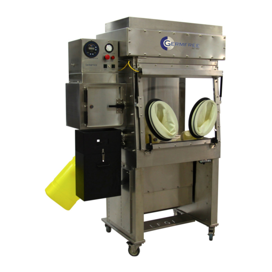
Parts Identifier Front of LFGI 1. Airlock 2. Control Panel 3. Prefilter Housing 4. Supply HEPA Filter Access Panel 5. Light Housing 6. Work Area 7. Gloveport 8. Viewing Panel Lift 9. Locking View Panel Latch 10. Sharps and Waste Removal Tubes 11. -
Page 18: Rea #2
Inside the Work Area #2 1. Electrical Outlet Connector 2. Airlock Inlet HEPA Filter Diffuser/Protector 3. Sliding Airlock Tray 4. Work Area HEPA Filter Diffuser/Protector Sharps and Waste 1. Outside of the Airlock 2. Sharps Tube 3. Waste Tube (will come with a cover and a clamp that can be removed if this feature is to be used. -
Page 19: Back Of The Control Panel
Back of the Control Panel 1. Supply Blower Control *Certifiers Only 2. Exhaust Blower Control *Certifiers Only 3. Unit Power Cord 4. Supply Blower Power Cord 5. Light Housing Power Cord 6. Exhaust Blower Power Cord 7. Work Area Outlet Power Cord 8. -
Page 20: Cleaning
Cleaning Outside the LFGI The outside of the LFGI can be cleaned at any time while the unit is closed and the procedure does not require Personal Protective Equipment (PPE) additional to that normally used when operating the LFGI. The stainless steel should be cleaned using a 70% alcohol solution or a solution specifically designated for the cleaning of stainless steel. -
Page 21: Start-Up
Start-Up ***The LFGI should be certified and venting options should be installed before operation. 1. Ensure the LFGI is plugged into a functioning outlet. 2. Install Sleeves and Gloves. Please refer to the Appendix on this topic. 3. Inspect Sleeves and Gloves. Please refer to the Appendix on this topic. Any damage must be replaced prior to start-up. -
Page 22: Operation
Operation For safe and efficient use of the Laminar Flow Glovebox /Isolator, you should take into account the equipment and materials necessary for the proposed operation and list the procedural details for each operation. The best way to accomplish this is through the use of a checklist and/or protocol that includes all equipment, apparatus, tools, products and supplies necessary for each specific procedure. -
Page 23: Airlock Operation
16. Open interior airlock door and pull sliding tray into the work area. 17. Remove items from the tray and slide tray back into the airlock. 18. Close and latch the inside airlock door. 19. Begin preparation. 20. Dispose of any waste by removing the stopper and pushing waste down the tube. Replace the stopper to maintain containment. -
Page 24: Usage
GERMFREE also recommends an airlock Purge when taking preparations from a contaminated work area. This reduces the chance for operators to be exposed to particulate contained within the work area. -
Page 25: D O
- disinfect and sanitize the work area at the beginning and end of each shift and after any large spills - change your hand gloves regularly. - sanitize gloves and work area with alcohol between each preparation. - adjust height and glove size to maximize operator comfort. - wear gloves and body coverings (gowns and hair nets) to eliminate unnecessary contamination from the largest source of contaminates…... -
Page 26: Sharps
Sharps The Sharps disposal system on the LFGI is designed to accommodate any sharps container with a 5” mouth or hinged lid up to a maximum size of 27” H x 20 “ D x 14.5” W Some BD part numbers that fit this description are as follows: 305491 300473... - Page 27 Any size bag can be attached to the outside of the Discharge Tube. The bag must be of proper strength and material to be compatible with discharge waste. Attach the bag to the tube with a rubber band and/or tape and make sure the bag is supported. A Stainless Steel Garbage Can is available as an option.
-
Page 28: Appendices
MAINTENANCE OR REPACKING INSTRUCTIONS, OR CLAIMS MADE AFTER THE DURATION OF THIS WARRANTY. GERMFREE makes no other express or implied warranty for this product. In the event that the exclusion of any implied warranty is ineffective under the law, the duration of the implied warranty will be one year from the purchase date. - Page 29 Maintenance Typical life span of a glove sleeve is 6 months and GERMFREE recommends that they be changed at that interval. See the appendix “Glove/Sleeve change” for instruction. Typical life span of a prefilter is 3 months but differing room conditions can require replacement more or less frequently.
-
Page 30: Bulb Replacement
The bulb should click into place on each end. 10. Test the light at the switch. If the light still doesn't come on you may need to replace the ballast. Contact GERMFREE @ 800-888-5357 for this replacement part. 11. Replace the light housing and secure the bolts. -
Page 31: Electronic Adjusting Stand
Ducting LFGI Venting Options The new NIOSH and USP <797> regulations have made it necessary that the airflow design of barrier isolators be flexible to accommodate a variety of conditions. For example, it is recommended that a safety cabinet used in the handling of hazardous drugs does not recirculate air within the work area. -
Page 32: Automated Compounders
Automated Compounders GERMFREE works with all compounding equipment manufacturers to ensure that the equipment fits and is located properly. There are options available to install sealed cable pass trough’s to allow monitors and printers to sit outside of the work area (as they should be). -
Page 34: Gloves
After corrective action is taken, allow 30 seconds for alarm to reset. Observe the digital read-out to ensure that the magnitude of the number is increasing. If number does not increase and alarm continues to sound call your certifier or GERMFREE at 800-888-5357 for further troubleshooting. -
Page 35: Procedure For Changing Gloves During Maintenance
Procedure for Changing Gloves During Maintenance Your standard two-part glove consists of: 1 Glove Sleeve 1 Disposable Glove 1 Glove Over Sleeve (GOS), a 3” diameter ring with three grooves on the outside 2 Glove O-rings, rubber rings that can stretch to fit around the GOS 2 Sleeve O-rings, rubber ring that can stretch to fit around the 10”... - Page 36 3) Stretch the Glove O-ring over the sleeve and secure in the last groove of the GOS (the one farthest away from your person). Glove O-Ring 4) Stretch the new glove cuff with both hands before trying to stretch it over the GOS will sometimes make the task easier as well as identify weaknesses in the glove before you get it into the work environment.
- Page 37 5) Take the second Glove O-ring and slide it over the glove, securing it in the GOS groove closest to you. Glove O-Ring 6) Push the entire glove and sleeve back into the work area.
-
Page 38: Sleeve Changes
Typically, new sleeves do not come with GOS or glove O-rings so save them from the existing sleeve. To order extras contact GERMFREE at 800-888- 5357. To replace while maintaining containment of the work area first remove the sleeve O-ring and move the sleeve to the outermost groove. - Page 39 the sleeve O-ring over the new sleeve to secure it. Reach inside of the glovebox with the other glove and pull the old sleeve off and into the work area. Dispose of Sleeve through the airlock. Glove and Sleeve Inspections A visual inspection of all glove and sleeve surfaces is recommended at the beginning and end of each day.
-
Page 40: Cleaning The Outside The Lfgi
Cleaning the LFGI- Heavy Duty (Rigorous) Outside the LFGI The outside of the LFGI can be cleaned at any time while the unit is closed and the procedure does not require PPE additional to that normally used when operating the LFGI. The stainless steel should be cleaned using a 70% alcohol solution or a solution specifically designated for the cleaning of stainless steel. - Page 41 7. Repeat steps 1-6 using sterile water to rinse any disinfectant away. 8. Repeat steps 1-6 using 70% IPA to sterilize the surfaces and run a purge cycle.
- Page 42 Inside the LFGI A disinfectant cleaner should be used, followed by 70% alcohol. This cleaning method, when properly performed, prevents dripping of dirty solution onto cleaned surfaces and does not carry contaminants from surfaces near the open front of the work area to the rear. It is recommended to clean the airlock prior to the work area.
- Page 43 If the LFGI is under negative pressure all cleaning steps must be performed as described above with the viewing panel closed and through attached sleeves/gloves. GERMFREE can provide an isolator cleaning tool to assist you in this function, contact us at 800-888-5357 for more information.
- Page 44 If all materials are wiped down prior to placement in the airlock, it should remain clean for a number of preparations in a row.
-
Page 45: Cleaning Agents
Thiosulfate This list is by no means comprehensive nor does it constitute endorsement by GERMFREE. Read the labels on the products you are currently using to categorize them then rotate cleaning agents to avoid developing any resistant strains. Contact your current disinfectant... -
Page 46: Cleaning Terms
Cleaning Terms Clean Free from disease or infectious agents <a pullorum-clean flock> <keep installations clean of TB infection> Deactivate 1 : to make inactive or ineffective 2 : to deprive of chemical activity Decontamination A process that reduces contaminating substances to a defined acceptance level. To make safe by eliminating poisonous or otherwise harmful substances, such as noxious chemicals or radioactive material. - Page 47 The American Heritage® Dictionary of the English Language, Fourth Edition copyright © 200 by Houghton Mifflin Company.
-
Page 48: Lfgi- Usp Specification Sheets
LFGI- USP Specification Sheets UNIT SPECIFICATIONS SHEET LFGI-3USP LAMINAR FLOW GLOVEBOX / ISOLATOR SECTION I. PERFORMANCE DATA The Laminar Flow Glovebox/Isolator provides the ultimate in both product and operator protection. The LFGI functions as a Glovebox while operating under negative pressure to meet NIOSH recommendations and as an Isolator under positive pressure to meet USP <797>... - Page 49 -Fully adjustable sharps container shelf accommodates most commercially available wide mouth or hinged top sharps collectors. (Examples BD Part # 305610 and 305491) Safety- -Lock-out handle requiring key for access to work area. -Digital pressure readout with low pressure alarm for work area. -Inward/Outward face velocity is 95-100 linear feet per minute at gloveport opening, to protect operator/product during massive breach of containment.
- Page 50 Exhaust- -Clean air plenum is external to the work area. -Constructed to allow for optional outside venting of exhaust air. -Constructed to allow for 3 exhaust options that can be factory set or changed by a certifier in- place -Venting is not required for operation but is optional. No Exhaust- Total Exhaust- no ~100% recycling of...
- Page 51 SECTION IV. UNIT DIAGRAM Made in the USA and available for purchase on the GSA...
- Page 52 UNIT SPECIFICATIONS SHEET LFGI-4USP LAMINAR FLOW GLOVEBOX / ISOLATOR SECTION I. PERFORMANCE DATA The Laminar Flow Glovebox/Isolator provides the ultimate in both product and operator protection. The LFGI functions as a Glovebox while operating under negative pressure to meet NIOSH recommendations and as an Isolator under positive pressure to meet USP <797>...
- Page 53 -Lock-out handle requiring key for access to work area. -Digital pressure readout with low pressure alarm for work area. -Inward/Outward face velocity is 95-100 linear feet per minute at gloveport opening, to protect operator/product during massive breach of containment. -Glove changes can be made without breaking containment. -Locking casters are standard, seismic anchors are available.
- Page 54 -Constructed to allow for 3 exhaust options that can be factory set or changed by a certifier in- place -Venting is not required for operation but is optional. No Exhaust- Total Exhaust- no ~100% recycling of recycling of air. Exhaust Connection 8”...
- Page 56 UNIT SPECIFICATIONS SHEET LFGI-6USP LAMINAR FLOW GLOVEBOX / ISOLATOR SECTION I. PERFORMANCE DATA The Laminar Flow Glovebox/Isolator provides the ultimate in both product and operator protection. The LFGI functions as a Glovebox while operating under negative pressure to meet NIOSH recommendations and as an Isolator under positive pressure to meet USP <797>...
- Page 57 -Lock-out handle requiring key for access to work area. -Digital pressure readout with low pressure alarm for work area. -Inward/Outward face velocity is 95-100 linear feet per minute at gloveport opening, to protect operator/product during massive breach of containment. -Glove changes can be made without breaking containment. -Locking casters are standard, seismic anchors are available.
- Page 58 -Constructed to allow for 3 exhaust options that can be factory set or changed by a certifier in- place -Venting is not required for operation but is optional. No Exhaust- Total Exhaust- no ~100% recycling of recycling of air. Exhaust Connection 8”...
-
Page 60: Certification Of Germfree Laminar Flow Glovebox / Isolator
Certification of GERMFREE Laminar Flow Glovebox / Isolator Models: LFGI 3 USP LFGI 4 USP LFGI 6 USP Product Overview The new LFGI USP Series Laminar Flow Barrier Isolator was introduced in December 2004 and replaces the LFGI ss Rx Series. Both the LFGI and the LFGI USP series provide the operator with and environment suitable to handle both sterile preparations and potentially hazardous pharmacy drugs. -
Page 61: Basic Operation
Basic Operation Supply air is brought into the unit through the top prefilters and directed through the Supply HEPA filter by a series of backwards-inclined motorized impellers. This unidirectional air moves downward to the work deck then splits to the front and back air grills. Then moves under the work tray and through the exhaust HEPA filter. - Page 62 Grid: Velocity Profile Test Grid 6" from back and sides, 6 3/4" from front LFGI 3 & 4, 5 5/8" apart left to right, 6" apart front to back LFGI 6, 6" apart left to right, 6" apart front to back Note: Above grid measurements made on work tray correspond to proper location at 12”...
- Page 63 Fig 2 Air recycle plenum (connection tip removed)
- Page 64 5. Light Housing Power Cord 6. Exhaust Blower Power Cord 7. Work Area Outlet Power Cord 8. Airlock Supply HEPA Filter Cover Replacement Filter Sizes & Part Numbers LFGI-PF3 LFGI-3USP Prefilter (18x37x1) 12/PKG LFGI-HF3S-N LFGI-3USP Supply HEPA (24x36x3) LFGI-HF3E-N LFGI-3USP Exhaust HEPA (12x24x6) LFGI-PF4 LFGI-4USP Prefilter (18x45.5x1) 12/PKG...
- Page 65 We strongly recommend that you consult Germfree Customer Support before any adjustments are made. Germfree has a general access code, 6756. This would unlock the settings if asked. Generally this code is entered at the factory and would remain unlocked.
- Page 66 Bulletin 102-0 Installation and Operation Manual Series A3 and A4 Differential Pressure Controller Sensocon, Inc. Phone: (863) 248-2800 Fax: (863) 248-2798 www.sensocon.com...
- Page 67 Installation and Operation Series A3 & A4 Manual Contents 1. Introduction 1.1. Model Number Configuration 1.2. Specifications 1.3. Dimensional Drawings 2. Installation 2.1. Mounting 2.2. Pressure Connections 2.3. Electrical Connections 3. Operation 3.1. Display 3.2. Key Function 4. Programming 4.1. Menu Structure 4.2.
-
Page 68: Introduction
Installation and Operation Series A3 & A4 Manual 1. INTRODUCTION The Sensocon A3 and A4 series of differential pressure controllers provide control of low differential pressure applications for air and other compatible non combustible gasses. These instruments have a large LED display for pressure indication, a LCD or OLED display for programming and additional LED’s to indicate % of output, setpoints and alarm status. -
Page 69: Dimensional Drawings
Installation and Operation Series A3 & A4 Manual Loop Resistance: 750 Ω Max (for internally sourced power); 1800 Ω Max (for externally sourced power of 36 VDC) Power Supply: Universal 16-265 VAC or VDC Housing Material: Glass Filled Nylon Enclosure Rating: Designed to meet NEMA 4X face; with optional cover the entire product is weatherproof Relays: (2) SPDT 8 Amps @ 250 VAC, 5A @30 VDC Electrical Connections: screw terminals... -
Page 70: Installation
Installation and Operation Series A3 & A4 Manual Optional weatherproof cover 2. INSTALLATION 2.1 Mounting Flush Mounting – For new applications, cut a 4 ” hole in the panel. Insert the control with the provided gasket through the hole and secure it to the panel with the provided mounting tabs and screws. - Page 71 Installation and Operation Series A3 & A4 Manual Surface Mounting – Surface mounting the Series A3 or A4 requires the optional weather proof cover. Once the control is wired and the weather proof cover has been attached, the control can be mounted to any flat surface with the four mounting screws provided with the cover.
-
Page 72: Pressure Connections
Installation and Operation Series A3 & A4 Manual 2.2 Pressure Connections Two 3/16” pressure connections are located on the back of the unit, labeled “High” and “Low”. For best results, connect 3/16” I.D. push on tubing to the pressure connections. If the High connection has a greater absolute value than the Low connection, the front display will give a positive value. -
Page 73: Operation
Installation and Operation Series A3 & A4 Manual 3. OPERATION 3.1 Display The series A3 and A4 were designed to give the user maximum feedback and flexibility. The process arch LED’s are designed to mimic the indicating needle of a mechanical gauge. The process arch will light up from left to right as the pressure moves away from zero. -
Page 74: Programming
Installation and Operation Series A3 & A4 Manual To move from one program menu to another, hold the up arrow or down arrow for one second to move up or down one menu level. The control will start in the “Main”... - Page 75 Installation and Operation Series A3 & A4 Manual Actuation 1 dir / rev 1 act Set Point 1 Delay value SP1 D Set Point 2 Setting db / lohi Set 2 Actuation 2 ...
- Page 76 Installation and Operation Series A3 & A4 Manual variable. Below are the possible parameters that would be shown with the factory default program. Set Point 1 Low (SP1 lo) Set Point 1 High (SP1 hi) Set Point 1 (SP1) ...
- Page 77 Installation and Operation Series A3 & A4 Manual HiLo Operation Pressure Set Point Hi Set Point Lo Time Relay Action Direct Acting Reverse Acting Setpoint DB Operation Pressure DB direct acting DB reverse acting Set Point Time Relay Action Direct Acting Reverse Acting ...
- Page 78 Installation and Operation Series A3 & A4 Manual Set Point Delay (SP1 D & SP2 D) – This variable sets the minimum amount of time that the process must be above or below the set point for the switch state to actuate.
- Page 79 Installation and Operation Series A3 & A4 Manual require a manual reset by holding the left arrow and right arrow simultaneously on the face of the control. Automatic (Auto) – For automatic reset Manual (Manual) – For manual reset ...
- Page 80 Installation and Operation Series A3 & A4 Manual (kPa) – Kilopascals (PSI) – Pounds per square inch (inHg) – Inches of mercury (mmHg) – Millimeters of mercury (mBAR) – Millibars (ftWc) – Feet of water column ...
- Page 81 Installation and Operation Series A3 & A4 Manual Dampening (Damp) – The control takes a pressure sample every 100 milliseconds. The dampening coefficient tells the control how many readings to average for the displayed value. Displaying readings with too few samples averaged may cause unstable readings as a result of vibration or pressure fluctuations.
-
Page 82: Main Menu
Installation and Operation Series A3 & A4 Manual 4.4 Secure Menu Zero (Zero) – This is a calibration parameter that allows re-calibration of zero. To re-zero the control, disconnect both pressure connections so they are open to atmospheric pressure and reset the value by holding the accept key. -
Page 83: Other Features
Installation and Operation Series A3 & A4 Manual Process Output Low (pol) – This parameter allows the 4-20 mA output to be scaled. The value set for this parameter will correspond to the 4 mA output. The default setting will be 0, but can be set at any value lower than Output High. -
Page 84: Limited Warranty
Installation and Operation Series A3 & A4 Manual PK-02 lockout programming key, a user may completely lock (or unlock) the face keypad of the control to eliminate the possibility of unwanted tampering of the control. To download programs from a control to a programming key, place the key within 1 to 6 inches of the OptiLink™... - Page 85 Installation and Operation Series A3 & A4 Manual (863) 248-2800 www.sensocon.com...
Need help?
Do you have a question about the LFGI-3USP and is the answer not in the manual?
Questions and answers