Table of Contents
Advertisement
Quick Links
Advertisement
Chapters
Table of Contents

Related Manuals for Beckhoff C9900-G05 Series


Summary of Contents for Beckhoff C9900-G05 Series
- Page 1 Manual | EN C9900-G05x Compact push-button extension 10/19/2020 | Version: 1.0...
-
Page 3: Table Of Contents
Table of contents Table of contents 1 Notes on the documentation ........................ 5 2 For your safety............................ 6 Description of safety symbols ...................... 6 Intended use ............................ 6 Fundamental safety instructions ...................... 7 Operator's obligation to exercise diligence .................. 7 3 Product overview............................ 8 C9900-G05x ordering options ...................... 9 Interface description ........................ 12 Description of the boards......................... 14 Board combination........................... 19... - Page 4 Table of contents Version: 1.0 C9900-G05x...
-
Page 5: Notes On The Documentation
Copyright © Beckhoff Automation GmbH & Co. KG. The reproduction, distribution and utilization of this document as well as the communication of its contents to others without express authorization are prohibited. Offenders will be held liable for the payment of damages. All rights reserved in the event of the grant of a patent, utility model or design. -
Page 6: For Your Safety
Exclusion of liability Liability on the part of Beckhoff Automation GmbH & Co. KG is excluded in the following cases: • Failure to comply with this documentation •... -
Page 7: Fundamental Safety Instructions
For your safety Fundamental safety instructions The following safety instructions must be followed when handling the compact push-button extensions. Application conditions • Do not use the push-button extensions in extreme environmental conditions. Protect the components against dust, moisture and heat. •... -
Page 8: Product Overview
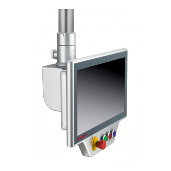
Product overview Product overview Fig. 1: C9900-G05x Compact Push-button Extension With the C9900-G05x compact push-button extensions, the central functions of a machine or plant such as emergency stop, start, stop and reset can be controlled with electromagnetic push-buttons. The push-button extensions are fitted below the touchscreen ex factory and are tailored to the CP39xx-00x0 Multi-touch Control Panel and the CP37xx-1600-00x0 Multi-touch Panel PC. -
Page 9: C9900-G05X Ordering Options
Product overview C9900-G05x ordering options Table 1: USB/ directly wired versions Order option Description C9900-G050 Compact push-button extension for CP3716-1600 or CP3916 with horizontal 15.6-inch display Push-button extension at the bottom, connection via USB (factory) and 19-pin round connector (customer) 3 push-button keys with signal lamp, type RAFI RAFIX 22FS+, round, 30 mm 1 emergency stop button, type RAFI RAFIX 22FS+ Labels for the push-button caps for individual labeling of each push-button can be ordered as accessories... -
Page 10: Table 2 Directly Wired Versions
Product overview Order option Description C9900-G056 Compact push-button extension for CP3724-1600 or CP3924 with horizontal 24-inch display Push-button extension at the bottom, connection via USB (factory) and 19-pin round connector (customer) 4 push-button keys with signal lamp, type RAFI RAFIX 22FS+, round, 30 mm 1 emergency stop button, type RAFI RAFIX 22FS+ Labels for the push-button caps for individual labeling of each push-button can be ordered as accessories... - Page 11 Product overview Order option Description C9900-G055 Compact push-button extension for CP3721-1600 or CP3921 with horizontal 21.5-inch display Push-button extension at the bottom, connection via 19-pin round connector (customer) 4 push-button keys with signal lamp, type RAFI RAFIX 22FS+, round, 30 mm 1 emergency stop button, type RAFI RAFIX 22FS+ Labels for the push-button caps for individual labeling of each push-button can be ordered as accessories...
-
Page 12: Interface Description
Product overview Interface description The following interface is provided for controlling the push-button extension: • Signal and power supply (XS01) Signal and power supply (XS01) The C9900-G05x push-button extensions are supplied with a nominal input voltage of 24 V, which may actually lie between 20.4 and 28.8 V. -
Page 13: Table 5 C9900-G051 And C9900-G053 Pin Assignment
Product overview Table 5: C9900-G051 and C9900-G053 pin assignment Signal Signal Emergency stop S1 input S3 input break contact 2 break contact 1 Emergency stop S1 output break contact 1 Emergency stop S1 input S3 output break contact 2 break contact 2 Emergency stop output S3 LED break contact 2... -
Page 14: Description Of The Boards
Product overview Description of the boards The boards used and their connectors are described and explained below. The C9900-G05x push-button extensions are wired ex factory to a 19-pin round connector. Named plug designations (CONxxx) can be found in the individual circuit diagrams. NOTE Switching voltage too high An excessively high switching voltage can lead to damage to property. -
Page 15: Fig. 4 A919 3-Button Board
Product overview Fig. 4: A919 3-button board The 3-button board has two K-bus interfaces 1, CON400 & CON401. "KBUS IN" connects the board to the USB-to-KBUS coupler and transmits one make contact and the LED per button. A jumper must be set on "KBUS OUT"... -
Page 16: Fig. 5 A920 4-Button Board
Product overview Fig. 5: A920 4-button board The 4-button board has two K-bus interfaces 1, CON400 & CON401. "KBUS IN" connects the board to the USB-to-KBUS coupler and transmits one make contact and the LED per button. A jumper must be set on "KBUS OUT"... -
Page 17: Fig. 6 A971 Emergency Stop Board
Product overview Fig. 6: A971 emergency stop board The emergency stop board has a connection strip 1, CON402, via which two break contacts of the emergency stop are connected to the 19-pin round connector. The assignment of the connection strip is listed in the table below. -
Page 18: Fig. 8 A973 4-Button Board
Product overview Table 11: Assignment of connection strip - A972 three-button board Connection strip Terminal point Description 24 V DC Input break contact 2.1 Output break contact 2.1 Output break contact 2.2 Input break contact 2.2 Input make contact 3.1 Output make contact 3.1 Output make contact 3.2 Input make contact 3.2 LED 1... -
Page 19: Board Combination
Product overview Connection strip Terminal point Description Input make contact 3.1 Output make contact 3.1 Output make contact 3.2 Input make contact 3.2 LED 1 LED 2 LED 3 LED 4 Input make contact 1.1 Output make contact 1.1 Output make contact 1.2 Input make contact 1.2 Input break contact 2.1 Output break contact 2.1 Output break contact 2.2... -
Page 20: Circuit Diagram - C9900-G050 And C9900-G052
Product overview Circuit diagram - C9900-G050 and C9900-G052 Fig. 9: Circuit diagram - C9900-G050 and C9900-G052 Version: 1.0 C9900-G05x... -
Page 21: Circuit Diagram - C9900-G054 And C9900-G056
Product overview Circuit diagram - C9900-G054 and C9900-G056 Fig. 10: Circuit diagram - C9900-G054 and C9900-G056 C9900-G05x Version: 1.0... -
Page 22: Circuit Diagram - C9900-G051 And C9900-G053
Product overview Circuit diagram - C9900-G051 and C9900-G053 Fig. 11: Circuit diagram - C9900-G051 and C9900-G053 Version: 1.0 C9900-G05x... -
Page 23: Circuit Diagram - C9900-G055 And C9900-G057
Product overview Circuit diagram - C9900-G055 and C9900-G057 Fig. 12: Circuit diagram - C9900-G055 and C9900-G057 C9900-G05x Version: 1.0... -
Page 24: Accessories
Product overview Accessories Optionally, pre-assembled signal and power supply cables are available. The respective signal and power supply cables can be ordered in four different lengths. Compatible accessories can be found in chapter 3.9.1 Signal and power supply - 19-pin round connector [} 24]. 3.9.1 Signal and power supply - 19-pin round connector Table 13: Signal and power supply cables... -
Page 25: Push-Button Caps And Inscription Labels
Product overview 3.9.2 Push-button caps and inscription labels Table 15: Optional push-button caps and inscription labels Options Description C9900-Z255 Blue push-button cap for individual assembly of a C9900-G0xx- push-button extension, make: Rafi, series FS+, diameter: 22.3 mm, 5 pieces C9900-Z256 Yellow push-button cap for individual assembly of a C9900-G0xx- push-button extension, make: Rafi, series FS+, diameter: 22.3 mm, 5 pieces C9900-Z257 Green push-button cap for individual assembly of a C9900-G0xx- push-button extension,... -
Page 26: Commissioning
5. Check the contents for visible shipping damage. 6. In case of discrepancies between the package contents and the order, or in case of transport damage, please inform Beckhoff Service (see chapter 9.1 Service and support [} 33]). Version: 1.0 C9900-G05x... -
Page 27: Commissioning In The Twincat System Manager
Commissioning Commissioning in the TwinCAT System Manager In the case of the push-button extensions C9900-G050, C9900-G052, C9900-G054 and C9900-G056, one make contact and the LED of each illuminated push-button are transmitted via USB to the control/ visualization PC. The steps required to connect the push-button extension in the TwinCAT System Manager are explained below. -
Page 28: Fig. 17 Twincat Select Device
Commissioning Fig. 17: TwinCAT Select device 4. Confirm the request with Yes, in order to look for boxes. Fig. 18: TwinCAT Scan boxes 5. Confirm the request whether to enable FreeRun with Yes. The device is inserted as a box in the tree view and displayed with the respective inputs and outputs (e.g. -
Page 29: Decommissioning
Decommissioning Decommissioning NOTE Damage to property due to power supply A connected power supply can cause damage during disassembly. • Disconnect the power supply from the device before commencing with the disassembly. As part of the decommissioning of the push-button extension, you must first disconnect the power supply and cables. -
Page 30: Maintenance
• Turn off the supply voltage before cleaning the device or replacing device components. Maintenance measures increase the efficiency of the device by ensuring long-term functionality. Repair Only the manufacturer may repair the device. If a repair should be necessary, contact Beckhoff Service (see chapter 9.1 Service and support [} 33]). Cleaning... -
Page 31: Troubleshooting
No supply of power via the 19-pin Check the cable for the power work round connector supply Other cause Call Beckhoff Service USB devices not found No USB connection Check the cables (TwinCAT System Manager) Check the transmitter box Other cause... -
Page 32: Technical Data
Technical data Technical data Table 18: Characteristics of the respective push-button extensions Properties Description Order designation C9900-G050, C9900-G051, C9900-G052, C9900-G053, C9900-G054, C9900-G055, C9900-G056, C9900-G057 Operating temperature CP37xx-1600-0020 0...45°C CP39xx-0000 0...55°C CP39xx-0010 0...50°C Shock resistance EN 60068-2-6: 10 to 58 Hz: 0.035 mm 58 to 500 Hz: 0.5 G (~ 5 m/s²) (sinusoidal vibration) Shock resistance (shock) -
Page 33: Appendix
Phone: + 49 (0) 5246/963-0 Fax: + 49 (0) 5246/963-198 E-mail: info@beckhoff.de The addresses of the worldwide Beckhoff branches and agencies can be found on our website at http:// www.beckhoff.com/. You will also find further documentation for Beckhoff components there. -
Page 34: Approvals
Appendix Approvals The Industrial PC is CE and EAC-certified. FCC approvals for the United States of America FCC: Federal Communications Commission Radio Frequency Interference Statement This device was tested and complies with the limits for a digital device of class A, according part 15 of the FCC regulations. - Page 35 List of figures List of figures Fig. 1 C9900-G05x Compact Push-button Extension................Fig. 2 C9900-G05x Signal and Power Supply ..................Fig. 3 A918 emergency stop board......................Fig. 4 A919 3-button board ........................Fig. 5 A920 4-button board ........................Fig. 6 A971 emergency stop board......................
- Page 36 List of tables List of tables Table 1 USB/ directly wired versions ......................Table 2 Directly wired versions......................... Table 3 C9900-G050 and C9900-G052 pin assignment ................Table 4 C9900-G054 and C9900-G056 pin assignment ................Table 5 C9900-G051 and C9900-G053 pin assignment ................Table 6 C9900-G055 and C9900-G057 pin assignment ................
- Page 38 Beckhoff Automation GmbH & Co. KG Hülshorstweg 20 33415 Verl Germany Phone: +49 5246 9630 info@beckhoff.com www.beckhoff.com...
Need help?
Do you have a question about the C9900-G05 Series and is the answer not in the manual?
Questions and answers