Alcatel-Lucent OmniSwitch 6900 Hardware User's Manual
Hide thumbs
Also See for OmniSwitch 6900:
- Hardware user's manual (62 pages) ,
- Troubleshooting manual (148 pages) ,
- User manual (53 pages)

Related Manuals for Alcatel-Lucent OmniSwitch 6900


Summary of Contents for Alcatel-Lucent OmniSwitch 6900
- Page 1 Part No. 060334-10, Rev. U July 2020 OmniSwitch 6900 Hardware Users Guide www.al-enterprise.com OmniSwitch 6900 Hardware Users Guide June 2020...
- Page 2 This user guide documents OmniSwitch 6900 hardware, including chassis and associated components. The specifications described in this guide are subject to change without notice. The Alcatel-Lucent name and logo are trademarks of Nokia used under license by ALE. To view other trademarks used by affiliated companies of ALE Holding, visit: www.al-enterprise.com/en/legal/ trademarks-copyright.
-
Page 3: Table Of Contents
How is the Information Organized? ................... x Documentation Roadmap ....................xi Related Documentation ....................xiii Technical Support ......................xiv Chapter 1 OmniSwitch 6900 ...................... 1-1 OmniSwitch 6900 Availability Features .................1-2 Power Supply Redundancy ..................1-2 Hot-Swapping ......................1-2 Hardware Monitoring ....................1-3 Chapter 2 Getting Started ......................2-1 Installing the Hardware ....................2-1... - Page 4 RJ45 Port Clearance ....................3-23 Chassis Status LEDs ....................3-24 OS6900-V72/C32/T48C6/X48C6 Status LEDs .............3-25 Network Port Status LEDs (OS6900-Q32 and OS6900-X72 Switches) ....3-26 4X10G Splitter Cable LED Indicators ..............3-27 OmniSwitch 6900 Expansion Modules .................3-28 OS-XNI-U4 ......................3-28 OS-XNI-U12 ......................3-28 OmniSwitch 6900 Hardware Users Guide June 2020...
- Page 5 Installing Power Supplies ..................3-54 Removing Power Supplies ..................3-55 Chassis Fan Tray ......................3-56 Airflow Direction ....................3-56 Replacing the Fan Tray ....................3-58 Grounding the Chassis ....................3-60 Monitoring Chassis Components ..................3-61 Viewing Chassis Slot Information .................3-61 OmniSwitch 6900 Hardware Users Guide June 2020...
- Page 6 Advertencia de la batería de litio ..............A-11 Advertencia sobre la tensión de operación ............. A-11 Advertencia sobre la desconexión de la fuente ..........A-11 Advertencia sobre una apropiada conexión a tierra ........A-12 OmniSwitch 6900 Hardware Users Guide June 2020...
- Page 7 Contents Leer “información importante de seguridad” ..........A-12 Advertencia de acceso restringido ..............A-12 Advertencia de pulsera antiestática ..............A-12 Clase de seguridad ..................A-12 Advertencia de fuentes de poder ..............A-12 OmniSwitch 6900 Hardware Users Guide June 2020...
- Page 8 Contents viii OmniSwitch 6900 Hardware Users Guide June 2020...
-
Page 9: About This Guide
About This Guide This OmniSwitch 6900 Hardware Users Guide describes OmniSwitch 6900 switch components and basic switch hardware procedures. Supported Platforms The information in this guide applies only to OmniSwitch 6900 switches. Who Should Read this Manual? The audience for this users guide is network administrators and IT support personnel who need to configure, maintain, and monitor switches and routers in a live network. -
Page 10: What Is In This Manual
Each chapter in this guide focuses on a specific hardware component or a set of hardware components. All descriptive, technical specification, and procedural information for a hardware component can be found in the chapter dedicated to that component. OmniSwitch 6900 Hardware Users Guide June 2020... -
Page 11: Documentation Roadmap
Once you have your switch up and running, you will want to begin investigating basic aspects of its hardware and software. Information about switch hardware is provided in the OmniSwitch 6900 Hardware Users Guide. This guide provide specifications, illustrations, and descriptions of all hardware components. - Page 12 CLI-to-MIB variable mapping information for all CLI commands supported by the switch. This guide can be consulted anytime during the configuration process to find detailed and specific information on each CLI command. OmniSwitch 6900 Hardware Users Guide June 2020...
-
Page 13: Related Documentation
Related Documentation The following are the titles and descriptions of all the OmniSwitch 6900 user manuals: OmniSwitch 6900 Hardware Users Guide • Complete technical specifications and procedures for all OmniSwitch 6900 chassis, power supplies, fans, and Network Interface (NI) modules. -
Page 14: Technical Support
Lucent Enterprise product’s features and functionality and on-site hardware replacement through our global network of highly qualified service delivery partners. With 24-hour access to Alcatel-Lucent Enterprise’s Service and Support web page, you’ll be able to view and update any case (open or closed) that you have reported to Alcatel-Lucent Enterprise’s technical support, open a new case or access helpful release notes, technical bulletins, and manuals. -
Page 15: Omniswitch 6900
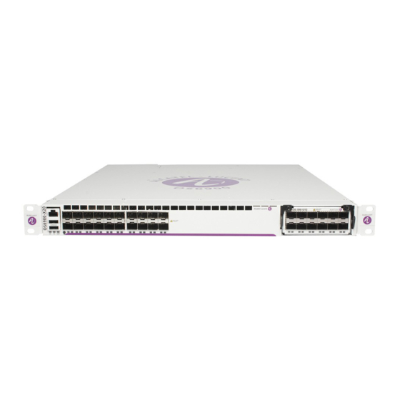
1 OmniSwitch 6900 The OmniSwitch 6900 (OS6900) is a family of aggregation switches that can also be installed as top-of- rack boxes in data centers. Refer to the information below for model number and component type. Model Number Description OS6900-X20... -
Page 16: Omniswitch 6900 Availability Features
“Hot-Swapping Plug-In Modules” on page 3-42 for detailed information on hot-swapping plug-in modules. For information on adding and removing power supplies and plug-in modules, refer to Chapter 3, “Chassis and Power Supplies.” page 1-2 OmniSwitch 6900 Hardware Users Guide June 2020... -
Page 17: Hardware Monitoring
The user enters “show” commands that output information to the console. The Show commands for all the features are described in detail in the OmniSwitch CLI Reference Guide. OmniSwitch 6900 Hardware Users Guide June 2020 page 1-3... - Page 18 OmniSwitch 6900 Availability Features OmniSwitch 6900 page 1-4 OmniSwitch 6900 Hardware Users Guide June 2020...
-
Page 19: Chapter 2 Getting Started
Electrical Requirements Note. Alcatel-Lucent switches must be installed by a professional installer. It is the responsibility of the installer to ensure that proper grounding is available and that the installation meets applicable local and national electrical codes. -
Page 20: Electrical Surge Warning
Ethernet cables (especially in new cable runs) to a suitable and safe earth ground before connect- ing them to the port. Note. Failure to follow the above recommendations could result in voiding the warranty of the affected ALE product. page 2-2 OmniSwitch 6900 Hardware Users Guide June 2020... -
Page 21: Unpacking And Installing The Switch
To protect your switch components from damage, read all unpacking recommendations and instructions carefully before beginning. Unpack your OmniSwitch 6900 chassis as close as possible to the location where it will be installed. Items Included Your OmniSwitch 6900 includes the following items: OmniSwitch chassis with power supplies, per order •... -
Page 22: Airflow Considerations
Sides. 2 inches minimum at left and right sides. Front. 6 inches minimum at front of chassis. Chassis Top View Note. Clearance is not required at the top and bottom of the chassis. page 2-4 OmniSwitch 6900 Hardware Users Guide June 2020... -
Page 23: Mounting The Switch
For information on modifying these settings, refer to the OmniSwitch AOS Switch Management Guide. Ethernet Management Port (EMP) Cable Requirements The OmniSwitch 6900 provides an Ethernet Management Port (EMP) on the front or rear panel of the chassis (depending on OS6900 model) for out-of-band management. There are specific cable type require- ments (i.e., straight-through or crossover) based on the device to which the EMP is connecting. - Page 24 Connections and Cabling Getting Started EMP to a Computer or Crossover Workstation For more on configuring Ethernet ports, refer to the OmniSwitch AOS Network Configuration Guide. page 2-6 OmniSwitch 6900 Hardware Users Guide June 2020...
-
Page 25: Booting The Switch
Command Line Interface (CLI) and configure basic information. Continue to “Your First Login Session” on page 2-8. OmniSwitch 6900 Hardware Users Guide June 2020 page 2-7... -
Page 26: Your First Login Session
The default welcome banner, which includes information such as the current software version and system date, is displayed followed by the CLI command prompt: Welcome to the Alcatel-Lucent OS6900-Q32 7.3.4, August 16, 2015. Copyright (c) 1994-2014 Alcatel-Lucent. All Rights Reserved. -
Page 27: Setting Ip Address Information For The Emp
(i.e. TELNET, FTP, HTTP, SSH or SNMP) until you have unlocked these remote session types. See “Unlocking Session Types” on page 2-10 for more information. OmniSwitch 6900 Hardware Users Guide June 2020 page 2-9... -
Page 28: Unlocking Session Types
Your First Login Session Getting Started Unlocking Session Types Security is a key feature on OmniSwitch 6900 switches. As described on page 2-8, when you access the switch for the first time, you must use a direct console port connection. All other session types (Telnet, FTP, WebView, and SNMP) are locked out until they are manually unlocked by the user. -
Page 29: Setting The System Time Zone
However, if no labeling system has been implemented or if you need to determine a switch’s location from a remote site, entering a system location can be very useful. To specify a system location, use the system location command. OmniSwitch 6900 Hardware Users Guide June 2020 page 2-11... -
Page 30: Viewing Your Changes
To view your current changes, enter show system at the CLI prompt. Saving Your Changes Once you have configured this basic switch information, save your changes by entering write memory at the CLI command prompt. page 2-12 OmniSwitch 6900 Hardware Users Guide June 2020... - Page 31 3 Chassis and Power Supplies This chapter includes detailed information on the OmniSwitch 6900 chassis, as well as fan tray and power supply components. Topics include: Technical specifications, page 3-4, page 3-7, page 3-10 page 3-14. • Switch mounting information, page 3-32.
-
Page 32: Omniswitch 6900 Chassis
Switch Management Guide.) Console Port Status LEDs 20 10G SFP+ Ports Expansion Module Slot OS6900-X20 Rear Panel Item Description Chassis Grounding Lug Fan Tray Power Supply Bays (OS6900-BP-F AC power supplies shown) page 3-2 OmniSwitch 6900 Hardware Users Guide June 2020... -
Page 33: Os6900-X40 Front Panel
Switch Management Guide.) Console Port Status LEDs 40 10G SFP+ Ports Expansion Module Slot OS6900-X40 Rear Panel SLOT Item Description Chassis Grounding Lug Expansion Module Slot Fan Tray Power Supply Bays OmniSwitch 6900 Hardware Users Guide June 2020 page 3-3... -
Page 34: Os6900-X20 And Os6900-X40 Chassis Specifications
Fully populated weights include fan tray, all installable power supplies and expansion modules. These figures do not include transceivers. Fully populated front panel (no expansion modules). See individual expansion modules for power consumption information. page 3-4 OmniSwitch 6900 Hardware Users Guide June 2020... - Page 35 (threshold or danger). Ambient temperature refers to the approximate room temperature. The ambient temperature will typically be lower than the chassis temperature. Due to different airflow characteristics, chassis temperatures will vary by model. OmniSwitch 6900 Hardware Users Guide June 2020 page 3-5...
-
Page 36: Os6900-X72 Front Panel
LED behavior for OS6900-X72 switches. OS6900-X72 Rear Panel Item Description Chassis Grounding Lug Ethernet Management Port (EMP) Status LED RJ-45 Ethernet Management Port (EMP) RJ-45 Console Management Port Fan Tray (Front-to-Rear Shown) Power Supply Bays page 3-6 OmniSwitch 6900 Hardware Users Guide June 2020... -
Page 37: Os6900-X72 Chassis Specifications
(threshold or danger). Ambient temperature refers to the approximate room temperature. The ambient temperature will typically be lower than the chassis temperature. Due to different airflow characteristics, chassis temperatures will vary by model. OmniSwitch 6900 Hardware Users Guide June 2020 page 3-7... -
Page 38: Os6900-T20 Front Panel
USB Port (For information on using a USB flash drive, refer to the OmniSwitch AOS Release 8 Switch Management Guide.) Console Port Status LEDs 20 10GBase-T Ports Expansion Module Slot OS6900-T20 Rear Panel Item Description Ethernet Management Port (EMP) Chassis Grounding Lug Fan Tray Power Supply Bays page 3-8 OmniSwitch 6900 Hardware Users Guide June 2020... -
Page 39: Os6900-T40 Front Panel
Switch Management Guide.) Console Port Status LEDs 40 10GBase-T Ports Expansion Module Slot OS6900-T40 Rear Panel Item Description Ethernet Management Port (EMP) Chassis Grounding Lug Expansion Module Slot Fan Tray Power Supply Bays OmniSwitch 6900 Hardware Users Guide June 2020 page 3-9... -
Page 40: Os6900-T20 And Os6900-T40 Chassis Specifications
Fully populated weights include fan tray, all installable power supplies and expansion modules. These figures do not include transceivers. Fully populated front panel (no expansion modules). See individual expansion modules for power consumption information. page 3-10 OmniSwitch 6900 Hardware Users Guide June 2020... - Page 41 The ambient temperature will typically be lower than the chassis temperature. Due to different airflow characteristics, chassis temperatures will vary by model. Note. OS6900-T20 and OS6900-T40 switches do not support Category 5 (Cat 5) cable OmniSwitch 6900 Hardware Users Guide June 2020 page 3-11...
-
Page 42: Os6900-Q32 Front Panel
QSFP+ ports 23 through 26: providing 40G support only QSFP+ ports 27 through 32: providing 40G or optional 4X10G splitter cable support *Refer to page 3-26 for detailed information on port LED behavior for OS6900-Q32 switches. page 3-12 OmniSwitch 6900 Hardware Users Guide June 2020... -
Page 43: Os6900-Q32 Rear Panel
Power Supply Bays OS6900-Q32-specific fan trays must be used in the chassis. OS6900-Q32 fan trays are not interchangeable with other OmniSwitch 6900 products. Fan trays are offered with two airflow options: Front-to-Rear; Rear-to-Front. OS6900-Q32 switches use 450W removable power supplies. Each power supply includes a cooling fan. -
Page 44: Os6900-Q32 Chassis Specifications
Fully populated chassis includes fan tray, two power supplies, all expansion plug-in modules and no transceivers. Maximum power consumption under full L2 traffic load includes fan tray, two power supplies and transceivers; no expansion plug-in modules. page 3-14 OmniSwitch 6900 Hardware Users Guide June 2020... -
Page 45: Os6900-V72 Front Panel
RJ45 10/100/1000 Ethernet Management Port (EMP) Console Port Reset Button (Used to reboot system) *Refer to page 3-25 for detailed information on port LED behavior. OS6900-V72 Rear Panel Item Description Power Supply Bays Fan Trays OmniSwitch 6900 Hardware Users Guide June 2020 page 3-15... -
Page 46: Os6900-V72 Chassis Specifications
(threshold or danger). Ambient temperature refers to the approximate room temperature. The ambient temperature will typically be lower than the chassis temperature. Due to different airflow characteristics, chassis temperatures will vary by model. page 3-16 OmniSwitch 6900 Hardware Users Guide June 2020... -
Page 47: Os6900-C32 Front Panel
RJ45 10/100/1000 Ethernet Management Port (EMP) Reset Button (Used to reboot system) *Refer to page 3-25 for detailed information on port LED behavior. OS6900-C32 Rear Panel Item Description Power Supply Bays Fan Trays OmniSwitch 6900 Hardware Users Guide June 2020 page 3-17... -
Page 48: Os6900-C32 Chassis Specifications
(threshold or danger). Ambient temperature refers to the approximate room temperature. The ambient temperature will typically be lower than the chassis temperature. Due to different airflow characteristics, chassis temperatures will vary by model. page 3-18 OmniSwitch 6900 Hardware Users Guide June 2020... -
Page 49: Os6900-T48C6 Front Panel
1G/10GBaseT ports (Ports 1-48) QSFP28 ports (Ports 49-54 - 40G/100G) *Refer to page 3-25 for detailed information on port LED behavior. OS6900-T48C6 Rear Panel Item Description Power Supply Bays Fan Trays OmniSwitch 6900 Hardware Users Guide June 2020 page 3-19... -
Page 50: Os6900-T48C6 Chassis Specifications
(threshold or danger). Ambient temperature refers to the approximate room temperature. The ambient temperature will typically be lower than the chassis temperature. Due to different airflow characteristics, chassis temperatures will vary by model. page 3-20 OmniSwitch 6900 Hardware Users Guide June 2020... -
Page 51: Os6900-X48C6 Front Panel
1G/10G SFP+ ports (Ports 1- 48) QSFP28 ports (Ports 49-54 - 40G/100G) *Refer to page 3-25 for detailed information on port LED behavior. OS6900-X48C6 Rear Panel Item Description Power Supply Bays Fan Trays OmniSwitch 6900 Hardware Users Guide June 2020 page 3-21... -
Page 52: Os6900-X48C6 Chassis Specifications
(threshold or danger). Ambient temperature refers to the approximate room temperature. The ambient temperature will typically be lower than the chassis temperature. Due to different airflow characteristics, chassis temperatures will vary by model. page 3-22 OmniSwitch 6900 Hardware Users Guide June 2020... -
Page 53: Rj45 Port Clearance
OmniSwitch 6900 Chassis RJ45 Port Clearance To ensure proper cable connector clearance on OS6900-T20 and OS6900-T40 switches and the OS-XNI-T8 expansion module, use RJ45 cables with the following maximum connector dimensions. OmniSwitch 6900 Hardware Users Guide June 2020 page 3-23... -
Page 54: Chassis Status Leds
3-35. Blinking Green The GRN power save feature is not supported on the OmniSwitch 6900. For OS6900 switches, this LED is used (in addition to the OK and PS LEDs) to indicate an airflow direction error between the power supplies and fan tray, or a missing fan tray. -
Page 55: Os6900-V72/C32/T48C6/X48C6 Status Leds
SFP28 Ports Green 25G link Amber 10G link QSFP28 Ports LED 1 - Green 100G LED 1 - Blue LEDs 1 - 4 Amber 4X25G LEDs 1 - 4 Purple 4X10G OmniSwitch 6900 Hardware Users Guide June 2020 page 3-25... -
Page 56: Network Port Status Leds (Os6900-Q32 And Os6900-X72 Switches)
“4X10G Splitter Cable LED Indicators” on page 3-27. Note. To manually configure network LED colors on OS6900-Q32 and OS6900-X72 switches, refer to the interfaces beacon command in the OmniSwitch AOS Release 8 CLI Reference Guide. page 3-26 OmniSwitch 6900 Hardware Users Guide June 2020... -
Page 57: 4X10G Splitter Cable Led Indicators
B displays next. 4. LED flashes white for a 3. LED flashes white for a short duration; status for short duration; status for sub port D displays next. sub port C displays next. OmniSwitch 6900 Hardware Users Guide June 2020 page 3-27... -
Page 58: Omniswitch 6900 Expansion Modules
SFP+ Ports Status LEDs Power Consumption 19W (fully populated) OS-XNI-U12 OS-XNI-U12 CLASS 1 LASER PRODUCT Item Description Lock Lever and Captive Screw SFP+ Ports Status LEDs Power Consumption 44W (fully populated) page 3-28 OmniSwitch 6900 Hardware Users Guide June 2020... -
Page 59: Os-Qni-U3
Lock Lever and Captive Screw SFP+ Ports Status LEDs QSFP+ Ports Power Consumption 37W (fully populated) CAUTION - TRANSCEIVERS ARE CLASS 1M LASER RADIATION WHEN OPEN. DO NOT VIEW DIRECTLY WITH OPTICAL INSTRUMENTS. OmniSwitch 6900 Hardware Users Guide June 2020 page 3-29... -
Page 60: Os-Xni-T8
Cat 5e; Cat 6; Cat 6a; Cat 7 Cable Distances 55 meters Cat 5e and Cat 6 100 meters Cat 6a and Cat 7 Note. OS-XNI-T8 modules do not support Category 5 (Cat 5) cable. page 3-30 OmniSwitch 6900 Hardware Users Guide June 2020... -
Page 61: Os-Xni-U12E
SFP+/FC Ports Status LEDs Power Consumption 31W (max. power, fully populated) Note. OS-XNI-U12E modules support 12X10G SFP+ or 12X2G/4G/8G Fibre Channel connections. An Alcatel-Lucent Data Center License is required for Fibre Channel operation. Plug-In Module Status LEDs State Description Port LEDs... -
Page 62: Mounting The Switch
Reliable Earthing. Reliable earthing of rack-mounted equipment should be maintained. Particular attention should be given to supply connections other than direct connections to the branch (e.g., use of power strips). page 3-32 OmniSwitch 6900 Hardware Users Guide June 2020... -
Page 63: Airflow Recommendations
Sides. 2 inches minimum at left and right sides. Front. 6 inches minimum at front of chassis. Chassis Top View Note. Clearance is not required at the top and bottom of the chassis. OmniSwitch 6900 Hardware Users Guide June 2020 page 3-33... -
Page 64: Front-To-Rear Airflow
Chassis and Power Supplies Front-to-Rear Airflow The OmniSwitch 6900 fan tray and power supplies are located at the rear of the switch and draw air through the intake vents located at the top-front of the chassis. The air is directed straight through the chassis’... -
Page 65: Airflow Mismatch
3-24, warnings displayed, switch will reboot when it reaches temperature danger threshold. Color Coding To help users avoid mismatched fan trays and power supplies, rear-to-front components are marked with purple color coding. (Front-to-rear components use standard product colors.) OmniSwitch 6900 Hardware Users Guide June 2020 page 3-35... -
Page 66: Blank Cover Panels
Note. Because they regulate airflow and help protect internal chassis components, blank cover panels should be installed over empty module slots and power supply bays at all times. Blank Panels and Chassis Airflow page 3-36 OmniSwitch 6900 Hardware Users Guide June 2020... -
Page 67: Rack-Mounting
The chassis has rack-mount flanges that support standard 19-inch rack mount installations. • Alcatel-Lucent does not provide rack-mount screws. Use the screws supplied by the rack vendor. • To prevent a rack from becoming top heavy, it is recommended that you install the switch at the •... - Page 68 OS6900 switches must be mounted using additional support braces (available from Alcatel-Lucent) or by attaching flanges to the mid portion of the chassis (using the threaded holes provided). Failure to properly mount the switch may result in the chassis sagging in the rack or damage to the switch and its components.
-
Page 69: Mid-Mounting The Chassis In The Rack
One person should lift and position the chassis until the mid-mount flanges are flush with the rack post. Align the holes in the flanges with the rack holes marked in step 3. OmniSwitch 6900 Hardware Users Guide June 2020 page 3-39... - Page 70 Once the holes are aligned, the second person should insert a screw through the bottom hole on each flange. Tighten both screws until they are secure. Once the flanges are aligned, install the remaining screws. Be sure that all screws are securely tightened. page 3-40 OmniSwitch 6900 Hardware Users Guide June 2020...
-
Page 71: Standalone (Non-Rack Mounted) Installations
Weight Considerations Depending on model type, an empty OmniSwitch 6900 chassis weighs up to 7.78 kg (17.15 lbs). When fully populated with fan tray, power supplies and plug-in modules, the OmniSwitch 6900 can weigh up to 10.86 kg (23.95 lbs). -
Page 72: Plug-In Modules
Wait for a ChassisSupervisor niMgr notification similar to the following to display on the console: +++ Expansion module 2 ready! Re-insert all transceivers into new module. Re-connect all cables to transceivers. page 3-42 OmniSwitch 6900 Hardware Users Guide June 2020... -
Page 73: Installing Plug-In Modules
When the bottom portion of the lever meets the chassis, be sure that the catches grab the chassis sheet metal, then push the lever up and back as shown. This will fully seat the module in the chassis backplane. OmniSwitch 6900 Hardware Users Guide June 2020... - Page 74 Plug-In Modules Chassis and Power Supplies Tighten the captive screw to complete the installation. page 3-44 OmniSwitch 6900 Hardware Users Guide June 2020...
-
Page 75: Removing Plug-In Modules
Pull down on the lock lever to release the plug-in module from the chassis backplane. Using the lock lever as a handle, pull the plug-in module straight back and out of the chassis. OmniSwitch 6900 Hardware Users Guide June 2020... -
Page 76: Power Supplies
Chassis and Power Supplies Power Supplies OmniSwitch 6900 power supplies are located at the rear of the switch chassis. Two slots are provided. If a second power supply is installed, it will assume a standby role. Please note that the OS6900 does not provide an on/off switch. Connecting an installed power supply to a power source will boot the switch. -
Page 77: Ac Power Supply Led States
No AC power is being provided to this power supply Flashing Green/Red Power supply warning Solid Red Power supply failure No AC power is being provided to any power supply installed in the chassis; all power supplies are effectively off OmniSwitch 6900 Hardware Users Guide June 2020 page 3-47... -
Page 78: Os6900-V72/C32 Ac Power Supply
T48C6/X48C6 power supplies. AC Power Supply LED States LED State Description Solid Green The power supply is operating normally and providing power to the chassis Solid Red Power supply failure No AC power. page 3-48 OmniSwitch 6900 Hardware Users Guide June 2020... -
Page 79: Os6900-T48C6/X48C6 Ac Power Supply
OS6900-V72/C32 power supplies. AC Power Supply LED States LED State Description Solid Green The power supply is operating normally and providing power to the chassis Solid Red Power supply failure No AC power. OmniSwitch 6900 Hardware Users Guide June 2020 page 3-49... -
Page 80: Os6900-X20/X40/X72/Q32/T20/T40 Dc Power Supply
No DC power is being provided to this power supply Flashing Blue/Red Power supply warning Solid Red Power supply failure No DC power is being provided to any power supply installed in the chassis; all power supplies are effectively off page 3-50 OmniSwitch 6900 Hardware Users Guide June 2020... -
Page 81: Os6900-V72/C32 Dc Power Supply
DC Power Supply LED States LED State Description Solid Green The power supply is operating normally and providing power to the chassis Solid Red Power supply failure No DC power. OmniSwitch 6900 Hardware Users Guide June 2020 page 3-51... -
Page 82: Os6900-T48C6/X48C6 Dc Power Supply
DC Power Supply LED States LED State Description Solid Green The power supply is operating normally and providing power to the chassis Solid Red Power supply failure No DC power. page 3-52 OmniSwitch 6900 Hardware Users Guide June 2020... -
Page 83: Dc Power Supply Connections
Observe proper polarity when connecting to a fuse panel. The cable wire leads must be connected as follows: Green/yellow - ground • Black - return • Red - -48VDC • Note. The battery return conductor is an Isolated DC Return (DC-1). OmniSwitch 6900 Hardware Users Guide June 2020 page 3-53... -
Page 84: Installing Power Supplies
Note. The chassis does not provide an on/off switch. Connecting a the power supplies to a power source will boot the switch. 1. Insert power supply. 2. Properly seat power supply, locking tab will click. 3. Plug the power cord into power supply socket. OS6900-V72/C32/X48C6/T48C6 (X48C6/T48C6 shown) page 3-54 OmniSwitch 6900 Hardware Users Guide June 2020... -
Page 85: Removing Power Supplies
Note. If you are not replacing the power supply, be sure to install a blank cover panel over the empty power supply bay. 1. Remove power cord. 2. Press the lock tab and remove power supply. 3. Install replacement power supply. OS6900-V72/C32/X48C6/T48C6 (X48C6/T48C6 shown) OmniSwitch 6900 Hardware Users Guide June 2020 page 3-55... -
Page 86: Chassis Fan Tray
Chassis and Power Supplies Chassis Fan Tray The OmniSwitch 6900 chassis houses a single fan tray with four independently-operating fan or multiple fan trays depending on the model. The fans are the main temperature control components for the switch, providing cooling airflow for all chassis components. This airflow is a crucial factor in the switch’s overall operability. - Page 87 This fan is available in either a front-to-rear or rear-to-front model. Note: Do not mix the OS6900-T48C6/X48C6 fans with the OS6900- V72/C32 fans. The OS6900-T48C6/X48C6 fan thumb screw is in the upper right (not shown). OmniSwitch 6900 Hardware Users Guide June 2020 page 3-57...
-
Page 88: Replacing The Fan Tray
Begin by loosening the two captive screws located at the left and right sides of the tray’s front panel. Pull the fan tray straight out of the chassis. Important. The switch should not run without a fan tray more than 60 seconds to prevent over heating. page 3-58 OmniSwitch 6900 Hardware Users Guide June 2020... - Page 89 When the fan tray is firmly seated in the chassis, tighten the two captive screws at the left and right sides of the fan tray’s front panel. 1. Loosen the captive screw. 2. Remove and replace fan tray. 3. Install new fan tray and tighten captive screw. OS6900-V72/C32/X48C6/T48C6 (V72/C32 shown) OmniSwitch 6900 Hardware Users Guide June 2020 page 3-59...
-
Page 90: Grounding The Chassis
Use this connector to supplement the ground provided by the AC power cord. To do so, install a Panduit Grounding Lug (type LCD8-10A-L) using 8AWG copper conductors to the paint-free area. Refer to the rear chassis views on page 3-2 for location details. page 3-60 OmniSwitch 6900 Hardware Users Guide June 2020... -
Page 91: Monitoring Chassis Components
To check the switch’s current temperature status, use the show temperature command: -> show temperature For more information about this command, see the “Chassis Management and Monitoring Commands” chapter in the OmniSwitch AOS Release 8 CLI Reference Guide OmniSwitch 6900 Hardware Users Guide June 2020 page 3-61... -
Page 92: Temperature Errors
To check the switch’s current fan tray status, use the show fan command. For example: -> show fan For more information about this command, see the “Chassis Management and Monitoring Commands” chapter in the OmniSwitch CLI Reference Guide. page 3-62 OmniSwitch 6900 Hardware Users Guide June 2020... -
Page 93: Pinouts
Chassis and Power Supplies Pinouts Pinouts OmniSwitch 6900 RS-232 console ports use either an RJ-45 connector or a USB connector. (Refer to diagrams below.) Three signals are used: Transmit Data (TXD), Receive Data (RXD) and Signal Ground (GND). The data sent out from the console port to the receiving device. -
Page 94: Rj-45 Console Port - Connector Pinout
10/100 Ethernet Port – RJ-45 Pinout Pin Number Description not used not used not used not used Gigabit Ethernet Port – RJ-45 Pinout Pin Number Description BI_DA+ BI_DA- BI_DB+ BI_DC+ BI_DC- BI_DB- BI_DD+ BI_DD- page 3-64 OmniSwitch 6900 Hardware Users Guide June 2020... -
Page 95: Regulatory Compliance And Safety Information
A Regulatory Compliance and Safety Information This appendix provides information on regulatory agency compliance and safety for OmniSwitch 6900 switches. Declaration of Conformity: CE Mark This equipment is in compliance with the essential requirements and other provisions of Directive 2004/108/EC (EMC), 2006/95/EC (LVD), 91/263/EEC (Telecom Terminal Equipment, if applicable), 1999/5/EC (R&TTE, if applicable). -
Page 96: China Rohs: Hazardous Substance Table
Declaration of Conformity: CE Mark Regulatory Compliance and Safety Information China RoHS: Hazardous Substance Table page A-2 OmniSwitch 6900 Hardware Users Guide June 2020... -
Page 97: Taiwan Rohs: Hazardous Substance Table
State of California to cause cancer and birth defects or other reproductive harm. For more information go to www.P65Warnings.ca.gov. Products are packaged using one or more of the following packaging materials: Corrugated Cardboard Corrugated Fiberboard Low-Density Polyethylene OmniSwitch 6900 Hardware Users Guide June 2020 page A-3... -
Page 98: Standards Compliance
The product bears the CE mark. In addition it is in compliance with the following other safety and EMC standards: All hardware switching modules used in an OmniSwitch 6900 switch comply with Class A standards. Modules with copper connectors meet Class A requirements using unshielded (UTP) cables. -
Page 99: Canada Class A Statement
RÈglement sur le brouillage radioèlectrique ètabli par le ministère des Communications du Canada. JATE This equipment meets the requirements of the Japan Approvals Institute of Telecommunications Equipment (JATE). OmniSwitch 6900 Hardware Users Guide June 2020 page A-5... -
Page 100: Cispr22 Class A Warning
Under such circumstances, the user may be requested to take appropriate countermeasure. Class 1M Laser Warning CLASS 1M LASER RADIATION WHEN OPEN. DO NOT VIEW DIRECTLY WITH OPTICAL INSTRUMENTS. page A-6 OmniSwitch 6900 Hardware Users Guide June 2020... -
Page 101: Network Cable Installation Warning
Deutsch: Dieses Gerät soll nur von Personal installiert oder gewartet werden, welches in elektrischen und mechanischen Grundlagen ausgebildet ist. Español: Estos equipos deben ser instalados y atendidos exclusivamente por personal adecuadamente formado y capacitado en técnicas eléctricas y mecánicas. OmniSwitch 6900 Hardware Users Guide June 2020 page A-7... -
Page 102: Invisible Laser Radiation Warning
Netzverbindungen getrennt sind bevor das Gerät gewartet oder bewegt wird. Español: Antes de empezar a trabajar con un sistema, asegurese que el interruptor está cerrado y el cable eléctrico desconectado. page A-8 OmniSwitch 6900 Hardware Users Guide June 2020... -
Page 103: Proper Earthing Requirement Warning
Erde angeschlossen werden. Español: Para EMC/EMI, cada fuente de alimentación de CC/CC requiere que el cable de tierra esté conectado desde cada fuente de alimentación de CC/CC a la conexión a tierra común. OmniSwitch 6900 Hardware Users Guide June 2020 page A-9... -
Page 104: Read Important Safety Information Warning
Español: Debido a las descargas electrostáticas (ESD) puede dañar los componentes del interruptor, debe seguir los procedimientos adecuados para eliminar la EDS de su persona y sus alrededores antes de manipular los componentes del interruptor. page A-10 OmniSwitch 6900 Hardware Users Guide June 2020... -
Page 105: Instrucciones De Seguridad En Español
Deseche las baterías usadas según las instrucciones del fabricante. Las instrucciones del fabricante son como sigue: Devuelva el módulo con la batería del litio a Alcatel-Lucent. La batería del litio será substituida en la fábrica de Alcatel-Lucent. -
Page 106: Advertencia Sobre Una Apropiada Conexión A Tierra
Para este propósito, Alcatel-Lucent proporciona una pulsera antiestática y un terminal que pone a tierra situados cerca de la parte superior derecha del chasis. Para que la pulsera antiestática sea eficaz en la eliminación de ESD, las fuentes de alimentación se deben instalar en el chasis y enchufar en las salidas de CA con descarga a...
Need help?
Do you have a question about the OmniSwitch 6900 and is the answer not in the manual?
Questions and answers