Table of Contents
Advertisement
1181113L2
DSL
DSX/DS1
ALM
ESF/ SF
(YEL) (GRN)
DSX-1
B8ZS/AMI
(YEL) (GRN)
LBK
TX
E
Q
RX
TX
M
O
N
RX
HDSL2 for General Distribution
Installation and Maintenance Practice
Document Number: 61223HDSL2L2-5B
June 2005
Part Number
Description
1181113L2
Total Access 3000 H2TU-C
1223001L2
220/E220 HDSL2 H2TU-C
1223003L2
DDM+ HDSL2 H2TU-C
1223004L2
3192 HDSL2 H2TU-C
1223004L12
3192M HDSL2 H2TU-C
1223024L2
T200 HDSL2 H2TU-R, Local/Span/60 mA Power
1223026L2
T200 HDSL2 H2TU-R, Span Powered
HDSL2
®
1223026L2
DSL
DS1
ALM
ESF/ SF
(YEL) (GRN)
B8ZS / AMI
DS1
(YEL) (GRN)
LLB / RLB
(YEL) (GRN)
LOC
L
B
K
REM
TX
C
M
U
O
S
N
T
RX
R
S
2
3
2
CLEI
T1L71YLA_ _
T1L722MA_ _
T1L734NA_ _
T1L746PA_ _
T1L9DEFA_ _
T1L8EJEC_ _
T1L8KMJC_ _
Advertisement
Table of Contents
Troubleshooting

Related Manuals for ADTRAN HDSL2


Summary of Contents for ADTRAN HDSL2
- Page 1 1223001L2 220/E220 HDSL2 H2TU-C 1223003L2 DDM+ HDSL2 H2TU-C 1223004L2 3192 HDSL2 H2TU-C 1223004L12 3192M HDSL2 H2TU-C 1223024L2 T200 HDSL2 H2TU-R, Local/Span/60 mA Power 1223026L2 T200 HDSL2 H2TU-R, Span Powered HDSL2 1223026L2 ESF/ SF (YEL) (GRN) B8ZS / AMI (YEL) (GRN)
-
Page 2: To The Holder Of The Manual
In no event will ADTRAN be liable for any special, incidental, or consequential damages or for commercial losses even if ADTRAN has been advised thereof as a result of issue of this publi- cation. -
Page 3: Revision History
HDSL2 for General Distribution Installation and Maintenance Practice Revision History Revision Date November 2004 June 2005 Conventions The following typographical conventions are used in this document: This font indicates a cross-reference link. First-time references to tables and figures are shown in this font. - Page 4 Training ADTRAN offers training courses on our products. These courses include overviews on product features and functions while covering applications of ADTRAN’s product lines. ADTRAN provides a variety of training options, including customized training and courses taught at our facilities or at customer sites. For more information about training, please contact us.
-
Page 5: Table Of Contents
HDSL2 Unit Information ........ - Page 6 HDSL2 Loopback and Control Codes ........
- Page 7 HDSL2 Edge Connector Wiring, continued ........
- Page 8 HDSL2 Facility Alarm History Screen ........
- Page 9 HDSL2 Loopback Control Codes ........
- Page 10 Contents HDSL2 for General Distribution Installation and Maintenance Practice 61223HDSL2L2-5B...
-
Page 11: Table 1. Hdsl2 Central Office Modules
HDSL2 for General Distribution PRODUCT DESCRIPTION The HDSL2 modules referenced in this document are used to deploy a T1 circuit using 2-wire metallic facilities. HDSL2 provides extended range to DS1/T1 transport while providing spectral compatibility with ADSL and other transport technologies. The ADTRAN HDSL2 Transceiver Unit for Central Office (H2TU-C) works in conjunction with the ADTRAN HDSL2 Transceiver Remote Unit (H2TU-R) to provide a DS1 service up to 12,000 feet on the local loop. -
Page 12: Figure 1. Adtran Hdsl2 Central Office Units For General Distribution
Product Description Illustrations Figure 1 illustrates the front panels of the ADTRAN H2TU-C modules approved for general distribution. 1223001L2 220 H2TU-C DDM+ H2TU-C P/N 1223001L2 P/N 1223003L2 Figure 1. ADTRAN HDSL2 Central Office Units for General Distribution HDSL2 for General Distribution Installation and Maintenance Practice... -
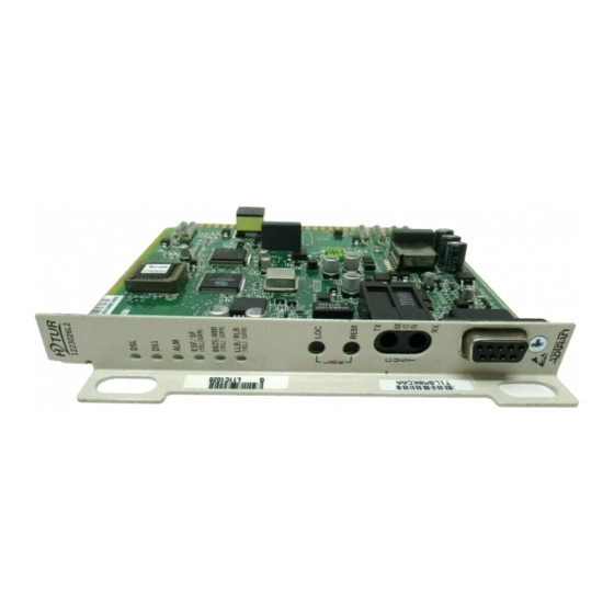
Page 13: Figure 2. Adtran Hdsl2 Remote Units For General Distribution
HDSL2 for General Distribution Installation and Maintenance Practice Figure 2 illustrates the front panels of the ADTRAN H2TU-R modules approved for general distribution. Figure 2. ADTRAN HDSL2 Remote Units for General Distribution The H2TU-R is a T200 mechanics card which will fit Type 200 or Type 400 mechanics enclosures, as listed in Table 3. -
Page 14: Table 4. Compliance Codes, H2Tu-C
Product Description Compliance ADTRAN HDSL2 modules are NRTL listed to the applicable UL standards. The HDSL2 modules are to be installed in a restricted access location and in a type “B” or “E” enclosure only. These devices comply with Part 15 of the FCC rules. Operation is subject to the following two conditions: 1. -
Page 15: Installation Guidelines
HDSL2 for General Distribution Installation and Maintenance Practice INSTALLATION GUIDELINES After unpacking an HDSL2 module, inspect it for damage. If damage has occurred, file a claim with the carrier, then contact ADTRAN Customer Service. For more information, refer to “Appendix D, Warranty”. -
Page 16: Figure 3. Hdsl2 Span Powering Diagram
H2TU-C An H2TU-C module is capable of span powering an H2TU-R module by applying current to the local loop. Current from 10 to 150 mA is coupled onto an HDSL2 span to power the H2TU-R module when required. Figure 3 HDSL2 Figure 3. -
Page 17: All Other Modules
5. Secure the module in place by pushing in on the ejector latch. All Other Modules To install any of the HDSL2 modules, with the exception of those explained above, perform the following steps: 1. Hold the unit by the front panel while supporting the bottom edge of the module and engage the enclosure edge. -
Page 18: Figure 4. Hdsl2 Edge Connector Wiring
Power and alarm signals are provided to the module through the backplane of the shelf. DSX-1 and HDSL2 loop signals are connected to the wire-wrap pins or mass termi- nation (amphenol) shelf connectors corresponding to the slot the module occupies. -
Page 19: Figure 5. Hdsl2 Edge Connector Wiring, Continued
HDSL2 for General Distribution Installation and Maintenance Practice R Tx DSX (In from DSX) R1 Rx DSX (Out to DSX) -48 VDC R HDSL2 Loop Fuse Alarm (to Alarm Module) T Tx DSX (In from DSX) T1 Rx DSX (Out to DSX) -
Page 20: Figure 6. Hdsl2 Edge Connector Wiring, Continued
MUX A Receive Data Figure 6. HDSL2 Edge Connector Wiring, continued PROVISIONING HDSL2 Configuration is performed via software control. For more information, refer to “Control Port Operation” on page 17. The provisioning settings can be viewed and manipu- lated through access to the firmware via the front panel RS-232 port. -
Page 21: Table 6. Provisioning Options
HDSL2 for General Distribution Installation and Maintenance Practice Provisioning Option 1. DSX-1 Line Build Out 2. DSX-1/DS1 Line Code 3. DSX-1/DS1 Framing 4. Force Frame Conversion 5. Smartjack Loopback 6. Loopback Time Out 7. Latching Loopback Mode 8. DS1 Tx Level 9. -
Page 22: Table 7. Total Access 3000 Additional Provisioning Options
EQ jack setting on the loopback/test screen. HDSL2 SYSTEM TESTING The ADTRAN HDSL2 system provides the ability to monitor the status and performance of the DSX-1 signals, DS1 signals, and HDSL2 loop signals. Detailed performance monitoring is provided by the front panel-mounted RS-232 control port (or via the SCU RS-232 port for the Total Access 3000). -
Page 23: H2Tu-C Bantam Jacks
HDSL2 for General Distribution Installation and Maintenance Practice H2TU-C Bantam Jacks The front panel of an H2TU-C module contains both metallic splitting ( bantam jacks. jacks provide an intrusive access point, interrupting signal access to the local loop. This will enable the user to transmit a test signal toward an H2TU-R module and to receive a test signal from an H2TU-R module. -
Page 24: Figure 7. Bantam Jack Arrangements
Table ADTRAN HDSL2 modules contain smartloop technology which constantly monitors the DSX-1 for a framing pattern. ADTRAN HDSL2 modules will initiate the proper loopback regardless of how the loopback control sequence is sent (framed or unframed). The loopback condition imposed in both cases is a logic level loopback at the point within an H2TU-C module where the DSX-1 signal passes into the HDSL2 modulators. -
Page 25: Table 8. Front Panel Loopback Pushbuttons
HDSL2 for General Distribution Installation and Maintenance Practice In addition to network-side loopbacks, an H2TU-C module provides customer-side loopbacks initiated by using either the terminal control port or in-band loop codes. For more infor- mation, refer to “Appendix A, HDSL2 supplied to the network. -
Page 26: Table 10. H2Tu-R Front Panel Led Indications
H2TU-C Front Panel Operation H2TU-C FRONT PANEL OPERATION LED indicators mounted on the front panel of the unit provide status of the HDSL2 circuit. Each indicator is described in Table 9. H2TU-C Front Panel LED Indications Front Label Status Panel... -
Page 27: Figure 9. Rs-232 (Db-9) Pin Assignments
Total Access System Controller Unit (SCU), P/N 1181018L1. This section will include Total Access H2TU-C screens separately where they differ from other HDSL2 screens. The terminal interface operates at data rates from 1.2 kbps to 19.2 kbps. (Total Access 3000 SCU default rate is 9.6 kbps.) -
Page 28: Figure 10. Adtran Hdsl2 Main Menu
Screens The screens illustrated in Figure 10 the ADTRAN HDSL2 technology. The circuit includes an H2TU-C module and an H2TU-R module. Logon to Main Menu A terminal session is initiated by entering multiple spacebar characters, which are used by an H2TU-C module to determine the speed of the terminal. -
Page 29: Figure 11. Logon Screen
“Virtual Terminal Control” Logon to Main Menu, Total Access 3000 H2TU-C Accessing the HDSL2 circuit information via the Total Access 3000 SCU control port requires the user to logon by entering a user name and password name is ADMIN. The default password is PASSWORD. -
Page 30: Figure 13. Access Module Menus Screen
Total Access 3000 shelf. Select the corresponding channel slot number for the desired H2TU-C. To the right of each access module listed, the current alarm state is indicated. When the module is selected, the ADTRAN HDSL2 Main Menu is displayed, from which the various Operation, Administrative, Maintenance, and Provisioning (OAM&P) screens are... -
Page 31: Figure 14. Total Access 3000 H2Tu-C Main Menu Screen
Figure 14. Total Access 3000 H2TU-C Main Menu Screen HDSL2 Unit Information The Unit Information screen component in the HDSL2 circuit. ADTRAN Technical Support contact numbers are also available from the Unit Information screen. This screen is shown as an example of an actual HDSL2 screen. -
Page 32: Figure 16. Provisioning Screen
Provisioning menu. To return to the previous screen, press To return to the Main Menu, press HDSL2 for General Distribution Installation and Maintenance Practice 16) displays current settings. To change a particular option . To re-deploy this unit, press Table 6 on page 11. -
Page 33: Figure 17. Provisioning Menu, Page 1
HDSL2 for General Distribution Installation and Maintenance Practice To re-deploy this unit, press Table 6 Table 7. The options shown in these tables are available with the H2TU-R (P/N 1223026L2). Some settings may differ when using different H2TU-Rs. Shelf: Slot: Unacknowledged Alarms: None Figure 17. -
Page 34: Figure 20. Span Status Screen, Total Access 3000
Shelf: Slot: Unacknowledged Alarms: Figure 20. Span Status Screen, Total Access 3000 HDSL2 for General Distribution Installation and Maintenance Practice 19) provides quick access to status information for each Press ESC to return to previous menu Span Status Screen ATTEN ______ <-00dB->... -
Page 35: Figure 22. Detailed Status Screen
HDSL2 for General Distribution Installation and Maintenance Practice Status Screen Legend Screen The Status Screen Legend (Figure screens. ______ |H2TUC | <------| ------>| |______| above 10e-7 BER Alarm Indicators: LOS = Loss of Signal LOF = Loss of Frame Sync... -
Page 36: Table 11. Auto In Service Status Indications
These times are also set from the Provisioning menu. System responses displayed in the status fields on this screen are shown in A single menu option is provided to view the Alarm History Screen. This screen is also available by selecting the HDSL2 Main Menu option. Shelf: Slot:... -
Page 37: Figure 24. Loopback And Test Commands Screen
Loopbacks and Test The Loopback and Test Commands screen initiate or terminate all available HDSL2 loopbacks. Each HDSL2 circuit component can be looped toward the network or customer from this screen. Unit self tests can also be initiated from this screen. A “Loop Down ALL Units” command will be available in lieu of the “Run Self Tests”... -
Page 38: Figure 25. Total Access 3000 H2Tu-C Loopback And Test Commands Screen
Option 1, (Re)start Pattern used to manually stop the test. The BERT only runs unframed patterns. When the BERT is running, option HDSL2 for General Distribution Installation and Maintenance Practice Total Access System Circuit ID: Loopback and Test Commands ______... -
Page 39: Figure 27. Select Data Pattern
HDSL2 for General Distribution Installation and Maintenance Practice Shelf: Slot: Unacknowledged Alarms: None ---------------------------------------------------- Test Direction: Unframed Pattern Generation: OFF Pattern: Line Coding: Bit Errors: Bit Error Rate: Pattern Sync: Pattern Sync Losses: Test Length (HH:MM:SS): Time Elapsed (HH:MM:SS): ---------------------------------------------------- When the BERT is started, the H2TU-R will automatically be put in loopback and the default test length of 2 hours will be initiated. -
Page 40: Figure 28. Bert Test Functions - Enter Test Timeout Option
Pattern Sync: Pattern Sync Losses: Test Length (HH:MM:SS): Time Elapsed (HH:MM:SS): ---------------------------------------------------- Figure 29. BERT Inject Errors Screen HDSL2 for General Distribution Installation and Maintenance Practice Total Access System Circuit ID: CUSTOMER Timeout Screen Test Timeout(Hr:Min) = 02:00 ---------------------------- 1. Change Timeout *NOTE: When timeout is set to 00:00, the test will run indefinitely. -
Page 41: Figure 30. Performance History, 15-Minute Line Data
HDSL2 for General Distribution Installation and Maintenance Practice Performance History The Performance History screens mance data in several different registers. At each 15-minute interval, the performance infor- mation is transferred to the previous 15-minute performance data register. This unit stores performance data in 15-minute increments for the last 24-hour period. -
Page 42: Figure 31. Performance Data Definitions, Loop
Under a SES-L or SES-P condition, the respective CV-L or CV-P count is inhibited. Previous Figure 32. Performance Data Definitions, Path HDSL2 for General Distribution Installation and Maintenance Practice Press ESC to return to previous menu Performance Data Definitions HDSL2 Framing CRC>=1 or LOSW>=1... -
Page 43: Scratch Pad, Circuit Id, Time/Date Screen
HDSL2 for General Distribution Installation and Maintenance Practice Scratch Pad, Circuit ID, Time/Date Screen The Scratch Pad, Circuit ID, Time/Date screen circuit information. The format for the items on this screen are as follows: • The scratch pad is for circuit-specific notes and can hold 50 alphanumeric characters in any combination. -
Page 44: Figure 34. Terminal Mode Screen
• Real-Time Update Mode (VT100) - This mode provides real-time updating of HDSL2 circuit conditions and provisioning options as changes occur. The default mode is Real-Time Update. -
Page 45: Figure 35. T1 Alarm History Screen
HDSL2 for General Distribution Installation and Maintenance Practice Alarm History The Alarm History screens are divided into three separate screens: • “T1 Alarm History” on page 35 • “HDSL2 Span History” on page 36 • “HDSL2 Facility Alarm History” T1 Alarm History The T1 Alarm History screen •... -
Page 46: Figure 36. Hdsl2 Span History Screen
Control Port Operation HDSL2 Span History The HDSL2 Span History screen • Loss of Sync for each HDSL2 receiver • Margin Threshold Alarm for each HDSL2 receiver • Attenuation Threshold Alarm for each HDSL2 receiver Circuit ID:HNTSVLALHDSL2 LOCATION ALARM --------------------------------------------------------------------------------... -
Page 47: Figure 37. Hdsl2 Facility Alarm History Screen
HDSL2 for General Distribution Installation and Maintenance Practice HDSL2 Facility Alarm History The HDSL2 Facility Alarm History screen • DC Open • Over-current (short) • Ground fault • Power cycle Circuit ID:HNTSVLALHDSL2 LOCATION ALARM -------------------------------------------------------------------------------- FACILITY DC OPEN FACILITY SHORT... -
Page 48: Figure 38. Event History Screen
'P' - Previous Page 'N' - Next Page HDSL2 for General Distribution Installation and Maintenance Practice 38) provides a log history of HDSL2 circuit events. The • HDSL/T1 PM Registers Reset • Line Code Option Change • Loopback Time Out Option Change •... -
Page 49: Figure 39. System Pm/Screen Report Option
Figure 39. System PM/Screen Report Option Clear PM and Alarm Histories The Clear PM and Alarm Histories option from the HDSL2 Main Menu initializes data from performance monitoring and alarm histories. Selecting this option from the Main Menu displays the prompt shown in... -
Page 50: Figure 41. Troubleshooting Screen
The Troubleshooting screens include the new feature “Splice Detection.” This and other new features are described in more detail in The Troubleshooting screen (Figure the screen plus ADTRAN contact information. Select from the following menu options: • “Troubleshooting Guidance” •... -
Page 51: Figure 42. Troubleshooting Guidance
HDSL2 for General Distribution Installation and Maintenance Practice Troubleshooting Guidance Selecting the option number associated with the Troubleshooting Guidance selection on the Troubleshooting screen causes an H2TU-C module to read the operational status of the circuit and return troubleshooting guidance to the probable cause of the trouble, as shown in... -
Page 52: Figure 43. General Information Screen
Control Port Operation General Information The General Information screen a summary of the deployment guidelines necessary to provision this HDSL2 circuit. Circuit ID:HNTSVLALHDSL2 HDSL2 Loop Guidelines for optimum operation ------------------------------------------- Non-loaded cable pair Single bridge tap < 2Kft Total bridge taps < 2.5Kft Bridge tap within 1000ft of transceiver may affect performance. -
Page 53: Figure 44. Chronic Circuit Problems Screen
HDSL2 for General Distribution Installation and Maintenance Practice Chronic Circuit Guidance Selecting the Chronic Circuit Guidance option displays the Chronic Circuit Problems screen (Figure 44). General information about circuits with bad splices is provided as well as a menu to the Bad Splice Detection feature. -
Page 54: Figure 45. View Splice Results Screen
Splice Histogram The Splice Histogram Screen make its result decision. For HDSL2, it displays six columns. The first and fourth columns, labeled Splice (feet), represent the distance away from the respective transceiver that the anomaly detector is evaluating. Columns 2 and 5 display the counters incremented by an H2TU-C module when it detects an anomaly. -
Page 55: Figure 46. Histogram Screen
HDSL2 for General Distribution Installation and Maintenance Practice Circuit ID: H2TUC Press C to Change Splice | (feet) | H2TUC ------ | ----- 0000 0250 0530 0810 1090 1370 1650 1930 2210 2490 2770 3050 3330 3610 Reset Splice Detector Choosing Reset Splice Detector will prompt to make sure a reset is desired. -
Page 56: Figure 47. Virtual Terminal Control Screen
When the remote session is completed, press terminate the session. Circuit ID:HNTSVLALHDSL2 Figure 47. Virtual Terminal Control Screen HDSL2 for General Distribution Installation and Maintenance Practice (Figure 47) is available on all modules except the Total Press ESC to return to previous menu... -
Page 57: Figure 48. Total Access 3000 H2Tu-C Flash Image Screen
HDSL2 for General Distribution Installation and Maintenance Practice Total Access 3000 H2TU-C Flash Upgrade Ability to download new firmware for the unit is available via the Total Access H2TU-C Flash Image screen (Figure 48). This feature allows the download and installation of a firmware upgrade. -
Page 58: Figure 50. Flash Upgrade, Y-Modem In Progress
4. Upload File. [Note: The screen will start displaying C's - this is normal.] =CCCC Figure 50. Flash Upgrade, Y-Modem in Progress HDSL2 for General Distribution Installation and Maintenance Practice Total Access System INFO Circuit ID:HntsvlALMn0103 Download H2TU-C via Y-Modem... -
Page 59: Figure 51. Download H2Tu-C Via Tftp
HDSL2 for General Distribution Installation and Maintenance Practice The Download H2TUC via TFTP menu from a remotely located computer/server to the H2TU-C. During TFTP transfers, the SCU continues to act as an intermediary to receive the file data from the remote computer and then send it to the H2TU-C unit. -
Page 60: Figure 52. Boot Block Status Screen
H4TU-C will require factory service to restore it to a functional state. Shelf: Slot: Unacknowledged Alarms: Figure 52. Boot Block Status Screen HDSL2 for General Distribution Installation and Maintenance Practice (Figure 52) provides the status of the Boot Block sector, which Total Access System MAJOR INFO... -
Page 61: Figure 53. Hdsl2 Deployment Guidelines
HDSL2 for General Distribution Installation and Maintenance Practice HDSL2 DEPLOYMENT GUIDELINES The ADTRAN HDSL2 system is designed to provide DS1 based services over loops designed to comply with carrier service area (CSA) guidelines. CSA deployment guidelines are given below: • All loops are nonloaded only. -
Page 62: Table 12. Hdsl2 Loss Values
Adhering to the guidelines should produce performance in excess of 10 MAINTENANCE The HDSL2 products detailed in this document do not require routine maintenance. In case of equipment malfunction, use the front panel bantam jack connectors to isolate the source of the problem. -
Page 63: Table 13. H2Tu-C Troubleshooting Guidelines
Loop has poor signal quality or loss of sync. Basic troubleshooting procedures should identify a problem with the cable pair. Errors are being taken on the DSX-1, DS1 or HDSL2 loop. The craft interface will identify the source. BERT tests toward the appropriate loopbacks should also reveal the source of the problem. -
Page 64: Table 14. H2Tu-R Troubleshooting Guidelines
For more information, refer to lines”. 2. Verify that loop loss at 196 kHz is not greater than 35 dB. 3. Verify that noise on the HDSL2 loop is within acceptable limits. 4. If steps through pass and loop sync is still not available, replace unit. -
Page 65: Table 15. H2Tu-C Product Specifications
HDSL2 for General Distribution Installation and Maintenance Practice SPECIFICATIONS Table 15 lists the product specifications for each H2TU-C included in this practice. Table 15. H2TU-C Product Specifications Specification H2TU-C Tx Pwr (Data) Level: H2TU-C Tx Pwr (Activation) Level: Maximum Loop Resistance:... - Page 66 Table 15. H2TU-C Product Specifications (Continued) Specification Dimensions: Total Access 3000 H2TU-C Temperature, Operating: Temperature, Storage: NRTL Listed to the applicable UL standards Total Access 3000 H2TU-C: HDSL2 for General Distribution Installation and Maintenance Practice Tests Diagnostics: Self-Test Local Loopback (H2TU-C) Remote Loopback (H2TU-R) Physical 5.35 in.
-
Page 67: Table 16. H2Tu-R Product Specifications
HDSL2 for General Distribution Installation and Maintenance Practice Table 16 lists the product specifications for each H2TU-R included in this practice. Table 16. H2TU-R Product Specifications Specification H2TU-C Tx Pwr (Data) Level: H2TU-C Tx Pwr (Activation) Level: Maximum Loop Resistance:... - Page 68 Table 16. H2TU-R Product Specifications (Continued) Specification Dimensions: T200 H2TU-R: Temperature, Operating: Temperature, Storage: NRTL Listed to the applicable UL standards HDSL2 for General Distribution Installation and Maintenance Practice Tests Diagnostics: Self Test Loopback (H2TU-R) initiated with T1 NIU in- band codes...
-
Page 69: Appendix Ahdsl2 Loopbacks
Appendix A HDSL2 Loopbacks HDSL2 LOOPBACK AND CONTROL CODES This appendix describes the operation of the HDSL2 system in detection of inband and ESF facility data link loopback codes. Upon deactivation of a loopback, the HDSL2 system will synchronize automatically. -
Page 70: Table A-1. Hdsl2 Loopback Control Codes
Note: All codes are in-band unless labeled ESF-DL. Note: All codes listed above must be sent for a minimum of 5 seconds in order for them to be detected and acted upon. HDSL2 for General Distribution Installation and Maintenance Practice NOTE Name... -
Page 71: Table A-2. In-Band Addressable Loopback Codes
HDSL2 for General Distribution Installation and Maintenance Practice Table A-2. In-Band Addressable Loopback Codes (All codes listed below must be sent for a minimum of 5 seconds in order for them to be detected and acted upon.) Function Code 11000 (2-in-5 pattern) - Page 72 Span 6767 Power (0110 0111 0110 0111) Disable HDSL2 for General Distribution Installation and Maintenance Practice Source Code and Response If unit is in loopback towards pattern, errors are periodically injected toward pattern as long as pat- tern is present.
-
Page 73: Hdsl2 Features
HDSL2 Features HDSL NEW ENHANCED FEATURE OVERVIEW The new HDSL2 and HDSL4 products contain new features to enhance their performance and help the customer reduce down time. The following features are described in this appendix: • “TScan” on page 1 •... -
Page 74: Splice Detection Feature
The Splice Detection Feature is included with this product as an aid to troubleshooting. Due to inconsistency in environmental condi- tions and their effect on telecommunications plant, ADTRAN cannot guarantee the accuracy of the measurements. Comparison to existing engineering drawings should provide exact locations of suspect splices indicated by ADTRAN algorithms. -
Page 75: Splice Detection Algorithm
In data mode, the detector will run periodically after synchronization is achieved. The HDSL2/HDSL4 transceiver monitors the loop for impedance changes that are of a magnitude to cause the received signal of the transceiver to be degraded. When a significant... -
Page 76: Figure B-2. Chronic Circuit Screen
This is reflected by the following screen statement: “Wire pairs pass all electrical tests and meet deployment guidelines.” HDSL2 for General Distribution Installation and Maintenance Practice B-2) displays general information about circuits with bad Press ESC to return to previous menu... -
Page 77: View Splice Results Screen
HDSL2 for General Distribution Installation and Maintenance Practice Splices that are varying in impedance will cause the HDSL data pump to see a reduced and/or fluctuating signal quality (margin). The HDSL data pump will attempt to track these changes, but when the changes become too severe, errors or loss of synchronization result. This is reflected by the symptoms described on this screen. -
Page 78: View Splice Histogram Screen
Figure B-3. Splice Results Screen View Splice Histogram Screen The View Splice Histogram Screen uses to make its result decision. For HDSL2, it displays six columns. The first and fourth columns labeled represent the distance from the respective transceiver that the Splice (feet) anomaly detector is evaluating. -
Page 79: Compatibility
HDSL2 for General Distribution Installation and Maintenance Practice Circuit ID: H2TUC Press C to Change Splice | (feet) | H2TUC ------ | ----- 0000 0250 0530 0810 1090 1370 1650 1930 2210 2490 2770 3050 3330 3610 Figure B-4. Splice Histogram Screen Compatibility The H2TU-C and H2TU-R both run local detectors;... -
Page 80: Using The Bad Splice Detector
If a cable pair acceptance test verified the cable pairs at turn up, and the Splice Detector was reset at that time, then the trouble- shooting procedure would include immediately with HDSL2 for General Distribution Installation and Maintenance Practice NOTE NOTE step 1 step 7 on the first trouble call. -
Page 81: Figure B-5. Event History Screen
• Brief power fault incidents (lightning) • Brief signal distortions In the older generation HDSL2 and HDSL4 transceivers, a brief short or GFI would cause a hardware control to quickly shut down the span power supply for safety reasons. The software would then detect the power fault and would hold the span supply off for 3 seconds. -
Page 82: Fast Retrain Feature
Fast Retrain Feature Fast Retrain is an ADTRAN proprietary feature whose intent is to minimize downtime when an intermittent non power-related impairment (bad splice, noise burst, etc.) affects the HDSL loop and cannot be bridged. -
Page 83: Front Panel Dsx And Mux Mode Test Access
Front Panel DSX and MUX Mode Test Access GENERAL Figure C-1 through Figure C-3 Figure C-7 are MUX fed modes of operation. From the Provisioning menu page 22), the Network Source option is used to choose either performing intrusive MUX mode testing, the equipment jack on the front panel can be configured to access the signal going to the Network or the Customer. -
Page 84: Figure C-2. Dsx Mon, Rx From Customer
BERT is sent to the customer. The TX EQ BERT is data from the customer. The direct connections. This test is intrusive, as it connects the from the customer data. HDSL2 for General Distribution Installation and Maintenance Practice 432 Ω 432 Ω jack (Figure RX MON 432 Ω... -
Page 85: Figure C-4. Mux Mon, Tx To Customer
HDSL2 for General Distribution Installation and Maintenance Practice T1 BERT Figure C-3. DSX EQ, Tx to Customer, Rx from Customer MUX MODE TEST ACCESS MUX Mode tests through a MUX on the Total Access 3000 shelf. MUX MON, Tx to Customer The Rx of the BERT receives data from the the data that the H2TU-C will transmit to the customer. -
Page 86: Figure C-6. Mux Eq, Tx To Network, Rx From Network
In the To Network direction. T1 BERT Figure C-6. MUX EQ, Tx to Network, Rx from Network HDSL2 for General Distribution Installation and Maintenance Practice jack (Figure RX MON 432 Ω 432 Ω jack, and the Rx of the BERT is connected to the... -
Page 87: Figure C-7. Mux Eq, Tx To Customer, Rx From Customer
HDSL2 for General Distribution Installation and Maintenance Practice MUX EQ, Tx to Customer, Rx from Customer The Tx of the BERT is connected to the jack (Figure C-7). The Tx of the BERT is then substituted for the data that the H2TU-C RX EQ sends to the customer. - Page 88 MUX Mode Test Access HDSL2 for General Distribution Installation and Maintenance Practice This page is intentionally blank. 61223HDSL2L2-5B...
-
Page 89: Warranty
Appendix D Warranty WARRANTY AND CUSTOMER SERVICE ADTRAN will replace or repair this product within the warranty period if it does not meet its published specifications or fails while in service. Warranty information can be found at www.adtran.com/warranty. Refer to the following subsections for sales, support, Customer and Product Service (CAPS) requests, or further information. - Page 90 ® Carrier Networks Division 901 Explorer Blvd. Huntsville, AL 35806...
Need help?
Do you have a question about the HDSL2 and is the answer not in the manual?
Questions and answers