
Related Manuals for Parker PCO2 Series


Summary of Contents for Parker PCO2 Series
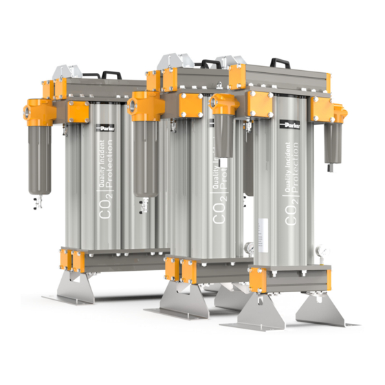
- Page 1 aerospace PCO2 - Quality Incident Protection climate control electromechanical PCO2-400 to PCO2-4800 filtration fluid & gas handling User Guide hydraulics Original Language pneumatics process control sealing & shielding...
- Page 2 ONLY USE PARKER GENUINE PARTS The use of Parker genuine parts is essential in maintaining product performance and failure to do so may result in: • Increased contamination in process streams • Spoilage and potential recall • Audit failure • Invalidate warranty •...
-
Page 3: Table Of Contents
1 Safety Information ......................................1 1.1 Markings and Symbols ..................................1 Description ........................................2 2.1 Stages of Purification...................................2 2.2 Technical Specification..................................2 2.2.1 Pressure Correction Factors ................................2 2.3 Weights and Dimensions ..................................3 2.4 Receiving and Inspecting the Equipment ............................4 2.4.1 Storage......................................4 2.4.2 Unpacking ....................................4 2.4.3 Overview of the Equipment ................................5 3 Installation &... -
Page 4: Safety Information
If the user employs an operating procedure, item of equipment or a method of working which is not specifically recommended by Parker Hannifin the user must ensure that the equipment will not be damaged or become hazardous to persons or property. -
Page 5: Description
2 Description The Parker domnick hunter PCO2 systems offer a comprehensive solution to preserve and guarantee the quality of gaseous carbon dioxide used in sparkling beverage bottling. Operating as a Quality Incident Protection system against potential carbon dioxide impurities, the system guarantees the gas quality so it remains within industry and company guidelines, preventing detrimental consequences to the finished end beverage, producers reputation and their bottom-line. -
Page 6: Weights And Dimensions
2.3 Weights and Dimensions PCO2-400 PCO2-800 to PCO2-4800 Height (H) Width (W) Depth (D) Clearance* Weight Model 1035 40.75 22.20 13.78 189.5 13.4 11.81 26.8 PCO2-400 1061 41.77 24.88 17.72 215.5 13.4 15.75 26.8 PCO2-800 1061 41.77 31.54 17.72 215.5 20.04 15.75 26.8... -
Page 7: Receiving And Inspecting The Equipment
2.4 Receiving and Inspecting the Equipment On receipt of the equipment carefully inspect the packaging for damage. If the packaging is damaged inform the delivery company immediately and contact your local Parker Hannifin office. 2.4.1 Storage If the equipment is to be stored prior to installation, do not remove it from the packaging. Ensure that it is stored in an upright position as indicated by the arrows on the packaging. -
Page 8: Overview Of The Equipment
2.4.3 Overview of the Equipment PCO2-400 PCO2-800 to PCO2-4800 Key: Item Description System Inlet System Outlet AA020P OIL-X Filter (PCO2-400 Models only) IP50-AA-0465GPCO2 Filter Manual Filter Drain Manifold Lifting Handle Manifold Hinge (PCO2-800 to PCO2-4800 Models) Desiccant Cartridge PCO2 Column Pressure Gauge Lifting Eye Bolt... -
Page 9: Installation & Commissioning
3 Installation & Commissioning Only competent personnel trained, qualified, and approved by Parker Hannifin should perform commissioning and service procedures. 3.1 Recommended system layout Liquid CO2 storage tank Vaporiser Stainless steel piping Pre filtration - Stage One PCO2 Unit Post filtration - Stage five... -
Page 10: Locating The Equipment
3.2 Locating the Equipment 3.2.1 Space Requirements 500mm (20ins) The equipment should be mounted on a flat surface capable of supporting its own weight plus the weight of all ancillary parts. The minimum footprint requirements are specified below, however there must be adequate space around the equipment to allow airflow and 500mm access for maintenance purposes and lifting equipment. -
Page 11: Operating The Equipment
4 Operating the Equipment 4.1 Starting the Equipment Note: On start-Up it is normal for the outlet temperature to increase for a limited period of time. Open the inlet valve slowly to gradually pressurise the PCO2 unit. Open the outlet valve slowly to re-pressurise the downstream piping. Do not open the inlet or outlet valves rapidly or subject the PCO2 unit to excessive pressure differential as damage may occur. -
Page 12: Servicing
Preventative Maintenance Parker recommend that the adsorbent cartridges and filter elements are exchanged within the recommended 12-month period or before the recorded cumulative mass of the unit has been exceeded or after a quality incident has occurred, whichever comes first. Please refer to the below table for the maximum mass flow of each model. -
Page 13: Preventative Maintenance Kits
5.3 Preventative Maintenance Kits PCO2-400 PCO2-800 to PCO2-4800 Required every 8000Hrs (12 months) Order Model PM Kit Number Kit Contents Quantity 1x Desiccant cartridges 2x Outlet block o-rings PCO2 400 MK-PCO2-400 2x P020AA Filter element 2x Filter bowl o-rings 2x Desiccant cartridges 2x Outlet block o-rings PCO2 800 MK-PCO2-800... -
Page 14: Maintenance Procedures
5.4 Maintenance Procedures 5.4.1 Cartridge Replacement Procedure (PCO2-400 Models Only) Ensure that the system is fully depressurised before carrying out the below maintenance procedures. Remove the M12 nuts from one side of the manifold. Using the handle, carefully lift and remove the manifold from the unit and store in a safe place. Ensure that the inlet and outlet piping is adequately supported before removing the manifold from the unit. -
Page 16: Oil-X Element Change Procedure
5.4.2 OIL-X Element Change Procedure Ensure that the filters are fully depressurised by opening the manual drain. Unscrew the filter bowl and remove the used element. We recommend the use of gloves when touching contaminated elements. Replace the o-ring located on the filter bowl with the new one provided within the 12 month Preventative Maintenance kits. -
Page 17: Cartridge Replacement Procedure (Pco2-800 To Pco2-4800 Models)
5.4.3 Cartridge Replacement Procedure (PCO2-800 to PCO2-4800 Models) The top manifold has been split into two sections in order to simplify the removal of the desiccant cartridges. Ensure that the system is fully depressurised before carrying out the below maintenance procedures. Remove the M12 nuts from one side of the manifold. -
Page 19: Ip50 Element Change Procedure
5.4.4 IP50 Element Change Procedure Ensure that the filters are fully depressurised by opening the 1/4” BSPT ball valves. Unscrew the filter bowl and then the used element from the tie rod. We recommend the use of gloves when touching contaminated elements. Replace the o-ring located on the filter bowl with the new one provided within the 12 month Preventative Maintenance kits. -
Page 20: Troubleshooting
6 Troubleshooting Problem Indication Possible Cause Action Required Bulk water carried over into the Check pre-filtration elements and PCO2 unit drains Compare flow through the PCO2 unit to rated flow Overflow of the PCO2 unit Check for modifications to the compressed air system Condensed water downstream of Check functioning of the... - Page 21 Declaration of Conformity Parker Parker Hannifin Manufacturing Limited GSFE Dukesway,Team Valley Trading Estate,Gateshead, Tyne & Wear,NE11 0PZ, UK PCO2 Carbon Dioxide Quality Incident Protection System PCO2-400, PCO2-800, PCO2-1600, PCO2-2400, PCO2-3200, PCO2-4000, PCO2-4800 2014/68/EU Directives Generally in accordance with ASME VIII Div 1:2017...
- Page 22 (from AT, BE, CH, CZ, DE, DK, EE, ES, FI, FR, IE, IL, IS, IT, LU, MT, NL, NO, PL, PT, RU, SE, SK, UK, ZA) © Parker Hannifin Corporation. All rights reserved. Catalogue: 176070001 Parker Hannifin Manufacturing Limited 01/20 Rev: A...
Need help?
Do you have a question about the PCO2 Series and is the answer not in the manual?
Questions and answers