Advertisement
Table of Contents
Advertisement
Table of Contents

Summary of Contents for CountyLine PHD 100
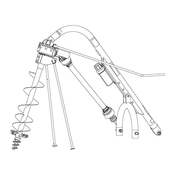
- Page 1 PHD 100 (602377) POST HOLE DIGGER 3-POINT MOUNTED * Auger sold separately THIS SAFETY ALERT SYMBOL IDENTIFIES IMPORTANT SAFETY MESSAGES IN THIS MANUAL. FAILURE TO FOLLOW THIS IMPORTANT SAFETY INFORMATION MAY RESULT IN SERIOUS INJURY OR DEATH. 602378 REV AA...
-
Page 2: Introduction
TO THE OWNER: Read this manual before operating your equipment. The information presented will prepare you to do a better and safer job. Keep this manual handy for ready reference. Require all operators to read this manual carefully and become acquainted with all adjustment and operating procedures before attempting to operate. -
Page 3: Table Of Contents
TABLE OF CONTENTS INTRODUCTION ..........2 GENERAL INFORMATION . -
Page 4: Specifications
SPECIFICATIONS Tractor Category Category 1 and Category 2 tractors only Gear Box Special alloy pinion gears and tapered roller bearings on both sides of each gear, 540 rpm Driveline Equipped with quick-tach yoke to fit standard 6 spline PTO (completely shielded) Augers Sold separately. -
Page 5: Safety Rules
SAFETY RULES ATTENTION! BECOME ALERT! YOUR SAFETY IS INVOLVED! CONTACT A PHYSICIAN IMMEDIATELY IF FLUID Safety is a primary concern in the design and ENTERS SKIN OR EYES. DO NOT DELAY. manufacture of our products. Unfortunately, our efforts to provide safe equipment can be wiped ... - Page 6 SAFETY RULES ATTENTION! BECOME ALERT! YOUR SAFETY IS INVOLVED! OPERATION Keep digger under control by running PTO at slowest speed possible (no faster than half-throttle Do not allow bystanders within 25 feet of the in 540 rpm range). area when operating, attaching, removing, assem- ...
- Page 7 SAFETY RULES ATTENTION! BECOME ALERT! YOUR SAFETY IS INVOLVED! dures may be required. Failure to follow these Never allow riders on power unit or attachment. instructions can result in serious injury or death. Power unit must be equipped with Roll Over ...
-
Page 8: Safety Decals
SAFETY & INSTRUCTIONAL DECALS ATTENTION! BECOME ALERT! YOUR SAFETY IS INVOLVED! Replace Immediately If Damaged! BE CAREFUL! Use a clean, damp cloth to clean safety decals. Avoid spraying too close to decals when using a pressure washer; high-pressure water can enter through very small scratches or under edges of decals causing them to peel or come off. - Page 9 SAFETY & INSTRUCTIONAL DECALS ATTENTION! BECOME ALERT! YOUR SAFETY IS INVOLVED! Replace Immediately If Damaged! PART NUMBER: S52020200 LOCATION: UPPER RIGHT SIDE OF BOOM PART NUMBER: S52056400 LOCATION: TOP OF BOOM, TRACTOR END PART NUMBER: S52020300 LOCATION: BOTH SIDES OF GEARBOX SHIELD PART NUMBER: S52019200 LOCATION: PTO DRIVE SHAFT SHIELD Safety 9...
-
Page 10: Operation
OPERATION ARNING The post hole digger and its individual components are NOT to be used for anything other than their intended use. The operator is responsible for the safe operation a doctor familiar with this form of injury or gan- of the equipment. - Page 11 IMPORTANT To dig properly, your digger must be able to raise or lower through the highest and lowest points of your lift ■ Under no circumstances should the PTO be arm travel without binding against the tractor frame. run in excess of 540 RPM. Check carefully BEFORE attaching the auger.
- Page 12 When the ground is too tough to penetrate with your Raise the implement as high as possible for transport- cutting edges and point, sharpen or replace them and ing. try again. These are replaceable parts and must be in good condition to penetrate. (An optional Hydraulic LODGED AUGER Down Pressure Kit is available.) ARNING...
-
Page 13: Pre-Operation Checklist
SHEAR BOLT REPLACEMENT PRE-OPERATION CHECKLIST ___ Review and follow all safety rules and safety ARNING decal instructions on pages 5 through 9. ___ Check that all safety decals are installed and in Never replace shear bolt or auger retaining bolt good condition. -
Page 14: Owner Service
OWNER SERVICE The information in this section is written for operators equipment for eyes, hair, hands, hearing, and head; who possess basic mechanical skills. For your protec- and respirator or filter mask where appropriate. tion, read and follow all safety information in this man- ROUTINE MAINTENANCE ual. - Page 15 INSTALL PARKING STAND Daily lubrication of the PTO slip joint is necessary. Fail- ure to maintain proper lubrication can result in damage to U-joints, gearbox, tractor PTO and/or driveline. STORAGE 1. Drain and change the oil in your gearbox. 2. Check and replace, where necessary, blades, bolts, nuts on the machine.
- Page 16 POST HOLE DIGGER OPTION tractor. Doing this, will cause rusting of the auger, but it is easy for one person to handle the unit. (HYDRAULIC DOWN FORCE KIT) For tough, hard soil conditions. This will allow operator REPLACE CUTTING EDGE to put 300-400 lbs.
-
Page 17: Troubleshooting 17
TROUBLESHOOTING PROBLEM POSSIBLE CAUSES & SOLUTION Auger will not dig Shear bolt sheared – install new shear bolt. Teeth dull – sharpen or replace. Ground too dry and hard – order optional down force kit, or wait until it rains. Auger turning too fast and bouncing –... - Page 18 TROUBLESHOOTING PROBLEM POSSIBLE CAUSES & SOLUTION PTO driveline failure Operator raising post hole digger too high above ground when PTO is engaged – causes excessive PTO joint operating angle. PTO is engaged while moving between holes. (Auger swings, which causes excessive PTO joint operating angle.) Improper use of a hard shear bolt –...
-
Page 19: Assembly Instructions
ASSEMBLY INSTRUCTIONS ARNING Mount PTO shaft storage bracket as shown on outside of A-Frame. NOTE: On tractors with 3-point arm spacing of 32 Keep hands, feet, hair, and clothing away from inches, place mounting pins on the outside of the equipment while engine is running. - Page 20 ATTACH GEARBOX TO BOOM INSTALL DRIVELINE 1. Place gearbox on level section of ground resting on output shaft shield. *Input shield removed for detail 2. Lower boom and align gearbox mount holes with boom mount hole. 3. Secure gearbox to boom using the supplied pin (4) and cotter pins (3).
- Page 21 ADJUST DRIVELINE LENGTH Cut Driveline 1. Place driveline half in a padded vise and cut shield Check Driveline Movement off at the determined length. 1. Remove auger from gearbox. 2. Attach driveline to the tractor PTO shaft. 3. Remove or place tractor drawbar in storage position.
- Page 22 FILL GEARBOX INSTALL HANDLE 1. Level gearbox and remove top fill plug and top sight plug on back side of gearbox. 2. Fill gearbox with SAE 90W gear lube until oil runs out of sight hole. 3. Install both plugs. 1.
- Page 23 NOTES Assembly 23 602378 REV AA 12/18/2018...
- Page 24 PHD100 POST HOLE DIGGER ASSEMBLY 24 Assembly 602378 REV AA 12/18/2018...
- Page 25 PHD100 POST HOLE DIGGER ASSEMBLY PARTS LIST PART DESCRIPTION 602390 BOOM 602376 A-FRAME 602415 GEAR BOX, COMPLETE (WITH 3, 4, 5, 6) S24070100 GEAR BOX 602389 LUG BRACKET S24075100 INPUT GUARD 602383 OUTPUT GUARD 602416 PTO SHAFT STORAGE BRACKET S24087600 MANUAL CANISTER 585648* 1/4"...
-
Page 26: Bolt Torque Chart
BOLT TORQUE CHART Always tighten hardware to these values unless a different torque value or tightening procedure is listed for a specific application. Fasteners must always be replaced with the same grade as specified in the manual parts list. Always use the proper tool for tightening hardware: SAE for SAE hardware and Metric for metric hardware. Make sure fastener threads are clean and you start thread engagement properly. - Page 27 BOLT SIZE CHART NOTE: Chart shows bolt thread sizes and corresponding head (wrench) sizes for standard SAE and metric bolts. SAE Bolt Thread Sizes 5/16 Metric Bolt Thread Sizes 10MM 12MM 14MM 16MM 18MM ABBREVIATIONS AG...............Agriculture MPa ............Mega Pascal ASABE ....American Society of Agricultural & N ..............
- Page 28 PART NO. 602378 A Blount International Brand Speeco Products Blount International P.O. Box 22127 Portland, OR 97269 U.S. Toll Free 800‐525‐8322 Email: customersupport@speeco.com Website:www.speeco.com...
Need help?
Do you have a question about the PHD 100 and is the answer not in the manual?
Questions and answers
Are thre 2 sizes of pto shafts
Can I get this phd-100 to to fit my Ford n8