Table of Contents
Advertisement
MANUAL
Valve and Line Accessories
Smith Meter
Model 210
®
Digital Electro-Hydraulic Set Stop
Installation / Operation / Service Manual
MN03010 Issue/Rev. 0.4 (6/17)
Advertisement
Table of Contents

Related Manuals for TechnipFMC Smith Meter 210

Summary of Contents for TechnipFMC Smith Meter 210
- Page 1 MANUAL Valve and Line Accessories Smith Meter Model 210 ® Digital Electro-Hydraulic Set Stop Installation / Operation / Service Manual MN03010 Issue/Rev. 0.4 (6/17)
- Page 2 24/7 Technical Support/Schedule a Technician: 1-844-798-3819 System Installation Supervision, Start-Up, and Commissioning Services Available Customer Support Contact Information: Customer Service TechnipFMC FMC Technologies Measurement Solutions, Inc. 1602 Wagner Avenue Erie, Pennsylvania 16510 USA P: +1 814 898-5000 F: +1 814 899-8927 measurement.solutions@TechnipFMC.com...
- Page 3 Model 210 Valve (I / O / S) Manual Table of Contents Table of Contents 1 – General ....................................4 1.1 – Receipt of Equipment ................................4 1.2 – Installation ................................... 4 1.3 – Electrical ....................................4 2 – Operation....................................5 2.1 –...
- Page 4 Model 210 Valve (I / O / S) Manual General 1 – General The Smith Meter Model 210 Digital Control Valves are hydraulically-operated, ® diaphragm-controlled valves, typically used in conjunction with either an AccuLoad or microLoad. Receipt of Equipment When the equipment is received, the outside packing case should be checked immediately for any shipping damage.
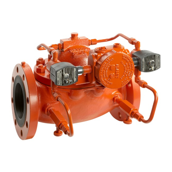
- Page 5 Model 210 Valve (I / O / S) Manual Operation 2 – Operation Principle The Smith Meter Model 210 Valve (Figure 1) fundamentally consists of a Smith ® Meter 200 Series Valve with two solenoid controls. A valve response control device, ®...
- Page 6 Model 210 Valve (I / O / S) Manual Operation Flow Rate GPM First Stage Trip* Final Gallons* Stage Trip* First High Flow Rate* Second High Flow Rate* Low Flow Start* 2,000 Gallons to Be Delivered *Field programmable. Caution: There must be sufficient pump capacity to achieve the flow rate set into the AccuLoad or microLoad or the valve may close slowly resulting in a spill.
- Page 7 Model 210 Valve (I / O / S) Manual Operation Step 8: Preset a small batch and after high flow is reached, initiate an emergency stop ('E' Stop). Record the volume throughput after initiation of the 'E' Stop and observe whether there was excessive line shock. If line shock was excessive, close the upstream solenoid isolation needle valve a little further to slow the valve closure rate.
- Page 8 Model 210 Valve (I / O / S) Manual Troubleshooting Guide 3 – Troubleshooting Guide Problem Cause Remedy Low or no flow. No pump pressure Start pump Upstream block valve closed Open valve Improper wiring Check wiring Downstream Model 13 Valve on 210 Valve Open needle valve closed AccuLoad or microLoad fuse blown...
- Page 9 Model 210 Valve (I / O / S) Manual Service and Maintenance 4 – Service and Maintenance The intent of this section is to illustrate proper service and provide maintenance interval guidelines of Smith Meter 210 digital control valves. ® Service / Maintenance Intervals The preset or device that is controlling the solenoids may be equipped with a means to count the number of solenoid actuations.
- Page 10 Model 210 Valve (I / O / S) Manual Service and Maintenance Figure 3 – Tubing Removal If the solenoids are to be disassembled, inspect the solenoid elastomers for any “chunking” or missing elastomer pieces. If abnormal wear is visible, the solenoid should be rebuilt or replaced.
- Page 11 Model 210 Valve (I / O / S) Manual Service and Maintenance Figure 5 – Cover Disassembly Caution! The cover spring(s) could cause the cover to release from the body unexpectedly. However, if the cover does not release from the body, use two flat headed screw- drivers to pry down, against the body as shown below.
- Page 12 Model 210 Valve (I / O / S) Manual Service and Maintenance Figure 7 – Cover Removal Figure 8 – Cover Removal Remove the spring(s) from the valve stem. Figure 9 – Cover Spring Removal Remove the stem assembly from the valve body. On the underside of the stem, note that the stem may have a flat machined surface.
- Page 13 Model 210 Valve (I / O / S) Manual Service and Maintenance Figure 10 – Stem Flat Surface Figure 11 – Stem Nut Figure 12 – Poppet Assembly Remove the stem nut with a socket or open ended wrench. Issue/Rev. 0.4 (6/17) ║ MN03010 • Page 13...
- Page 14 Model 210 Valve (I / O / S) Manual Service and Maintenance Figure 13 – Stem Nut Removal Remove the lock washer, back-up plate and diaphragm washer. Note: The back-up plate and diaphragm washer have a tight fit around the stem. Ensure not to gall the threads of the stem while removing the back-up plate.
- Page 15 Model 210 Valve (I / O / S) Manual Service and Maintenance Figure 16 – Diaphragm Removal Inspect the lower diaphragm washer for any defects. If none are present, the diaphragm washer can be left on the stem. If there are visible defects (i.e. sharp edges, warpage, etc.), the diaphragm washer should be replaced.
- Page 16 Model 210 Valve (I / O / S) Manual Service and Maintenance Figure 18 – Diaphragm Install a new diaphragm O-ring. Use caution while pulling the O-ring down the threads of the stem. Figure 19 – Diaphragm O-ring Apply a light coating of petroleum jelly to the top diaphragm O-ring and the stem. Figure 20 –...
- Page 17 Model 210 Valve (I / O / S) Manual Service and Maintenance Inspect the upper diaphragm washer for any defects. If none are present, install the diaphragm washer. If there are visible defects (i.e. sharp edges, warpage, etc.), the diaphragm washer should be replaced. Use caution when installing the washer and ensure not to gall the threads.
- Page 18 Model 210 Valve (I / O / S) Manual Service and Maintenance Figure 24 – Back-up Plate Installation Install the lock washer on the stem. Figure 25 – Lock Washer Apply LOCTITE Nickel Anti-Seize 77164 on the threads of the stem before placing ®...
- Page 19 Model 210 Valve (I / O / S) Manual Service and Maintenance Remove the stem assembly from the vice and install the stem into the seat of the valve. DO NOT slide the diaphragm over the studs at this point. Figure 27 –...
- Page 20 Model 210 Valve (I / O / S) Manual Service and Maintenance Figure 29 – Stem Assembly Installation While the stem is lifted (if the valve has been removed from the piping), install the spring(s) over the stem against the backup plate. Figure 30 –...
- Page 21 Model 210 Valve (I / O / S) Manual Service and Maintenance Figure 32 – Cover Installation With the stem still lifted (if the valve has been removed from the piping), install every other nut until pressure can be relived from the cover. While tightening the nuts, tuck the excess of the diaphragm under the rabbit of the cover.
- Page 22 Model 210 Valve (I / O / S) Manual Service and Maintenance Figure 34 – Cover Installation Continue tightening the cover nuts by hand until they require a wrench and the rabbit of the cover completely covers the valve body. Install the remaining nuts by hand. As the nuts are being tightened, check for gap uniformity of the valve body and cover.
- Page 23 Model 210 Valve (I / O / S) Manual Service and Maintenance If the valve has been removed from the piping, the valve can be rested on the inlet or outlet flange to allow proper leverage. Figure 35 – Torque Cover Nuts Install the junction box and junction box bracket and install solenoids.
- Page 24 Model 210 Valve (I / O / S) Manual Service and Maintenance Figure 37 – Tubing Installation Re-wire solenoid connections. Ensure to reference proper preset controller or PLC manuals for this process. Once the valve is completely assembled, refer to the Start-up and Field Adjustments section for proper valve tuning procedure.
- Page 25 Model 210 Valve (I / O / S) Manual Service and Maintenance 5 – Related Publications The following literature can be obtained from FMC Technologies Measurement Solutions Literature Fulfillment at measurement.fulfillment@fmcti.com or online at www.fmctechnologies.com/mesurementsolutions. When requesting literature from Literature Fulfillment, please reference the appropriate bulletin number and title. Model 210 Digital Electro-Hydraulic Set-Stop Specifications ............
- Page 26 FMC Technologies Measurement Solutions, Inc. Germany Operation 500 North Sam Houston Parkway West, Smith Meter GmbH Suite 100 Regentstrasse 1 TechnipFMC.com Houston, Texas 77067 USA 25474 Ellerbek, Germany P:+1 281.260.2190 P:+49 4101 304.0 © TechnipFMC 2017 MN03010 Issue/Rev. 0.4 (6/17)
Need help?
Do you have a question about the Smith Meter 210 and is the answer not in the manual?
Questions and answers
where can i find the part number on the model210digital electro hydraulic set stop