Toshiba JK Series Instruction Manual
Medium voltage controllers, oem power cells - fixed and withdrawable types, 360a, 7.2kv maximum
Hide thumbs
Also See for JK Series:
- Instructions manual (51 pages) ,
- Instruction manual (44 pages) ,
- Instruction manual (46 pages)

Related Manuals for Toshiba JK Series


Summary of Contents for Toshiba JK Series
- Page 1 Document: VF010H09 Rev. 4 INSTRUCTION MANUAL INSTALLATION - OPERATION - MAINTENANCE JK Series Medium Voltage Controllers OEM Power Cells - Fixed and Withdrawable Types 360A, 7.2kV Maximum Issued: 3/20...
- Page 3 Toshiba International Corporation. © Copyright 2020 Toshiba International Corporation. TOSHIBA® is a registered trademark of Toshiba Corporation. All other product or trade references appearing in this manual are registered trademarks of their respective owners.
- Page 4 Contacting TIC’s Customer Support Center Toshiba International Corporation’s Customer Support Center can be contacted to obtain help in resolving any system problem that you may experience or to provide application information. The Support Center is open from 8 a.m. to 5 p.m. (CST), Monday through Friday. The Center’s toll free number is US (800) 231-1412/Fax (713) 937-9349 CAN (800) 872-2192 MEX 01 (800) 527-1204.
-
Page 5: Safety
SAFETY Page 1 General Safety Information DO NOT attempt to install, operate, maintain, or dispose of this equipment until you have read and understood all of the product safety information and directions that are contained in this manual. Safety Alert Symbol The Safety Alert Symbol is comprised of an equilateral triangle enclosing an exclamation mark. - Page 6 DO NOT remove or cover any of these labels. If the labels are damaged or if additional labels are required, contact the Toshiba Customer Support Center. Labels attached to the equipment are there to provide useful information or to indicate an imminently hazardous situation that may result in serious injury, severe property and equipment damage, or loss of life if safe procedures or methods are not followed as outlined in this manual.
-
Page 7: Storage/Disposal
STORAGE/DISPOSAL Page 3 Storage • Store in a well-ventilated location, preferably in the original packaging, if the equipment will not be used upon receipt. • Store in a cool, clean, and dry location. Avoid storage locations with extreme temperatures, rapid temperature changes, high humidity, moisture, dust, corrosive gases, or metal particles. -
Page 8: Table Of Contents
TABLE OF CONTENTS Page 4 SAFETY ..............................1 STORAGE/DISPOSAL .......................... 3 INTRODUCTION ........................... 5 GENERAL DESCRIPTION ........................6 RECEIVING, INSPECTION AND HANDLING ..................13 INSTALLATION ........................... 15 OPERATION ............................19 MAINTENANCE ..........................20 SPECIFICATIONS ..........................21 SCHEMATIC DIAGRAMS ........................22 KEY INTERLOCK OPTION ......................... -
Page 9: Introduction
INTRODUCTION Page 5 It is the intent of this manual to provide a guide for the installation of Toshiba medium voltage control components in NEMA Class E controllers manufactured by original equipment manufacturers (OEMs). This manual consists of a section of general safety instructions and is marked throughout with warning symbols. -
Page 10: General Description
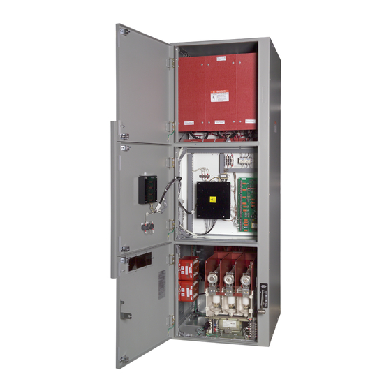
Each JK Series OEM power cell is a modular unit containing a vacuum contactor, isolation switch, power fuse clips and other basic components necessary for the OEM to construct an AC general-purpose NEMA Class E medium voltage controller. - Page 11 GENERAL DESCRIPTION Page 7 POWER CELLS WITH FIXED-TYPE CONTACTORS - MAJOR COMPONENTS A. Isolation Switch (Fig. 3) Power is switched on and off by a fixed- mounted, externally operated, three-pole isolation switch. When the switch is in the OFF position, incoming power is isolated from the power cell interior by an automatic shutter.
- Page 12 GENERAL DESCRIPTION Page 8 D. Interlocks – Mechanical The isolation switch is mechanically interlocked with the vacuum contactor and the compartment door. Three separate interlocks are provided, as described below. a. Door Interlock Bracket A door interlock bracket is provided to prevent opening closing medium...
- Page 13 GENERAL DESCRIPTION Page 9 E. Interlocks - Electrical Control Power Interlock (CPI) control power interlock (CPI) microswitch (Fig. 9) which is directly driven by the operation of the switch handle. This normally open switch is closed only when the handle is fully ON.
- Page 14 GENERAL DESCRIPTION Page 10 POWER CELLS WITH WITHDRAWABLE TYPE CONTACTORS - MAJOR COMPONENTS A. Isolation Switch (Fig. 10) The isolation switch is the same design as that used for the fixed-type contactor, except in this configuration the switch accepts a direct connection from the line stabs of the removable contactor carriage.
- Page 15 GENERAL DESCRIPTION Page 11 C. Service Drawer (Fig. 12) The withdrawable contactor carriage is moved in and out of the power cell on a built-in slide-out service drawer. The drawer has four locating pins on top of it. When the contactor carriage is placed on the drawer, these pins engage four holes in the bottom of the carriage, which serve to align it properly.
- Page 16 GENERAL DESCRIPTION Page 12 E. Interlocks - Mechanical When the withdrawable contactor carriage is inserted into power cell, mechanical interlocking is established between the isolation switch, vacuum contactor compartment door. a. Door Interlock Bracket A door interlock bracket is provided to prevent opening closing medium...
-
Page 17: Receiving, Inspection And Handling
Fig. 15 Lifting Method for Power Cell (Fixed-Type and Withdrawable Contactor) 4) File a claim with the carrier for any damaged or missing items and immediately notify the nearest Toshiba representative. Do not install or energize equipment that has been damaged. Damaged... - Page 18 Maximum weight of Removal of the contactor carriage may be accomplished by the use of an optional Toshiba carriage is 135 lbs. WARNING carriage lifting...
-
Page 19: Installation
INSTALLATION Page 15 OEM ENCLOSURE DESIGN The right front corner of the OEM structure These power cells should be totally enclosed in should include a flange of approximately 4 sheet metal structures that comply with the inches in width with a cutout for the operating applicable requirements of NEMA Standards handle to extend through. - Page 20 INSTALLATION Page 16 Fig. 18 Line and Load Terminal Locations with Withdrawable Type Contactor 5.00 5.00 8.84 4.37 (3) LINE TERMINAL 1.00 5.36 4.53 4.53 (3) LINE TERMINAL 4.25 (3) LOAD TERMINAL 20.03 9.60 9.75 Fig. 19 Line and Load Terminal Locations with Fixed Type Contactor...
- Page 21 INSTALLATION Page 17 30.00 MINIMUM CELL MODULE CELL RIGHT FRONT POST WALL STARTER DOOR INTERLOCK 36.00 MINIMUM 1.43 1.13 1.29 1.16 OEM CELL DOOR ENCLOSUR 0.42 2.81 FIGURE A 0.23 3.44 0.23 TOP VIEW 0.27 4 - φ 0.173 0.50 FIGURE A FIGURE B –...
- Page 22 INSTALLATION Page 18 MAIN CIRCUIT CABLING Cables which connect to the power cell should be routed to avoid interference with sharp edges and moving parts. Minimum bending radius for the type of cable used should be observed. Power cables should be braced and/or laced to withstand short-circuit forces wherever such cables are unsupported.
-
Page 23: Operation
The medium two-high stacking arrangements voltage compartment door cannot be closed requires the use of a Toshiba JK lifting unless the release lever is pushed in. A device. mechanical interlock prevents the isolation switch from being closed unless the medium Manually lifting heavy voltage door is closed. -
Page 24: Maintenance
Refer GENERAL DESCRIPTION section for the location of moving joints should occasionally the handle mechanical interlocks and the lubricated with a light coat of Toshiba B9 grease. CPI electrical interlock. Fig. 23 Interlock Sequence Check... -
Page 25: Specifications
SPECIFICATIONS Page 21 CONTACTOR RATINGS TABLE 1 CONTACTOR TYPE HCV-5HA/5HAM/7HA/7HAM (Magnetically Held) Maximum Voltage 7200 Volts Rated Operational Current 400 Amps Rated Thermal Current 450 Amps 7000 Amps RMS Sym. @ 5 kV Max Interrupting Capacity (NEMA Class E1)-5HA 4500 Amps RMS Sym. @ 7.2 kV Max Interrupting Capacity (NEMA Class E1)-7HA 7200 Amps RMS Sym. -
Page 26: Schematic Diagrams
SCHEMATIC DIAGRAMS Page 22 Fig. 24 Suggested Schematic for Medium Voltage FVNR Starter with Withdrawable Contactor... - Page 27 SCHEMATIC DIAGRAMS Page 23 Fig. 25 Suggested Schematic for Medium Voltage FVNR Starter with Fixed Mount Contactor...
-
Page 28: Key Interlock Option
KEY INTERLOCK OPTION Page 24 KEY INTERLOCK The OEM kit can be provided with an option for installing a key switch on the operating handle mechanism, which operates the isolation switch. The frame can be provided (see Fig. 26) for locking the switch in the closed (option K1) or open (option K2) position. - Page 29 KEY INTERLOCK OPTION Page 25 Fig. 27 Key Interlock Mounting Option...
- Page 32 Motors & Drives Division 13131 West Little York Road | Houston, TX 77041 Tel: 713-466-0277 | US: 800-231-1412 | CAN: 800- 872-2192 www.toshiba.com/tic Printed in USA...