Table of Contents
Advertisement
Quick Links
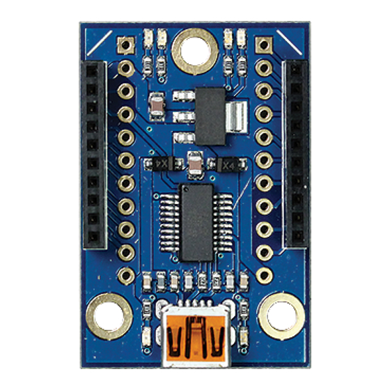
XBee USB Adapter Board (#32400)
This low cost XBee USB Adapter Board comes ready to connect to your
XBee module and your computer's USB port.
included for optional use with breadboards or thru-hole boards, converting
the 2mm pin spacing to breadboard friendly 0.1" spacing.
mounting holes allow for secure installation into your project.
Features
Provides an easy interface for configuring an XBee Module via a
computer's USB port
4 status indicator LEDs for Power, RSSI, Associate and mode
(sleep/ON)
Converts XBee 2mm pin spacing to 0.1" pin spacing
Provides easy pluggable wire or solder connections
Includes mounting holes
Pin-out compatible with our other XBee Adapter boards
Key Specifications
Power requirements: 3.3 V pass-through to XBee module
Communication: Serial pass-through to XBee module
Operating temperature: -40 to +158°F (-40 to +70°C)
PCB dimensions: 1.5 x 1.0 in (3.81 mm x 2.54 cm)
Packing List
(1) XBee USB Adapter Board PCB (SMD components pre-soldered)
(2) 10-pin 2mm sockets – installed, no soldering required on Rev B and later boards
(1) 40-pin SIP header – optional, requires soldering
Tools Required
Soldering equipment (iron, solder, flux; always wear safety glasses when soldering)
Diagonal cutters or Exacto knife
Additional Items Required
XBee module (802.15.4, Pro, 900HP, or WiFi series; search XBee at parallax.com for options)
USB A to Mini B cable (#805-00006)
Copyright © Parallax Inc.
Web Site: www.parallax.com
Forums: forums.parallax.com
Sales: sales@parallax.com
Technical: support@parallax.com
A 40-pin SIP header is
XBee USB Adapter Board (#32400)
Office: (916) 624-8333
Fax: (916) 624-8003
Sales: (888) 512-1024
Tech Support: (888) 997-8267
Convenient
v2.0 3/9/2015 Page 1 of 5
Advertisement
Table of Contents

Related Manuals for Parallax XBee USB Adapter Board


Summary of Contents for Parallax XBee USB Adapter Board
- Page 1 Technical: support@parallax.com Tech Support: (888) 997-8267 XBee USB Adapter Board (#32400) This low cost XBee USB Adapter Board comes ready to connect to your XBee module and your computer’s USB port. A 40-pin SIP header is included for optional use with breadboards or thru-hole boards, converting the 2mm pin spacing to breadboard friendly 0.1”...
- Page 2 PCB as shown and solder them in place from the bottom side of the board. (Note, female sockets are pre- installed on Rev B and later boards.) Copyright © Parallax Inc. XBee USB Adapter Board (#32400) v2.0 3/9/2015 Page 2 of 5...
- Page 3 Step 4 (optional): Insert the two 11-pin SIP headers into the bottom of the adapter board as shown and solder them in place from the top. Copyright © Parallax Inc. XBee USB Adapter Board (#32400) v2.0 3/9/2015 Page 3 of 5...
- Page 4 If you wish to connect your XBee USB Adapter to your PC then you will first need a USB A to Mini B cable (sold separately). You will also need to install the FTDI VCP drivers. You may obtain the latest drivers by pointing your web browser to http://www.parallax.com/usbdrivers. You may also obtain these drivers from the FTDI website at http://www.ftdichip.com/Drivers/VCP.htm.
- Page 5 Changed LED colors, see LED Status Indicators, page 4. USB Mini B connector style changed and moved flush with edge of PCB, and PCB resized slightly, to accommodate XBee WiFi modules. Copyright © Parallax Inc. XBee USB Adapter Board (#32400) v2.0 3/9/2015 Page 5 of 5...
Need help?
Do you have a question about the XBee USB Adapter Board and is the answer not in the manual?
Questions and answers