Advertisement
Quick Links
Operating Instructions
To raise or lower the spike, press and hold either the UP or
DOWN button on the remote control. The anchor will only
Operating Instructions
Operating Instructions
Operating Instructions
continue to move so long as you keep the button depressed.
To raise or lower the spike, press and hold either the UP or
To raise or lower the spike, press and hold either the UP or
To raise or lower the spike, press and hold either the UP or
Auto Mode: Double tapping (pressing and releasing 2 times
DOWN button on the remote control. The anchor will only
DOWN button on the remote control. The anchor will only
DOWN button on the remote control. The anchor will only
within 1 second) either the UP or the DOWN buttonon the
continue to move so long as you keep the button depressed.
continue to move so long as you keep the button depressed.
continue to move so long as you keep the button depressed.
remote control will cause the anchor to retract or deploy au-
Auto Mode: Double tapping (pressing and releasing 2 times
Auto Mode: Double tapping (pressing and releasing 2 times
Auto Mode: Double tapping (pressing and releasing 2 times
tomatically. The anchor will continue to move in said direction
within 1 second) either the UP or the DOWN button
within 1 second) either the UP or the DOWN button
within 1 second) either the UP or the DOWN button
until it either retracts completely (up) or senses a solid bottom
on the remote control will cause the anchor to retract or
on the remote control will cause the anchor to retract or
on the remote control will cause the anchor to retract or
deploy automatically. The anchor will continue to move
deploy automatically. The anchor will continue to move
deploy automatically. The anchor will continue to move
surface (down).
in said direction until it either retracts completely (up) or
in said direction until it either retracts completely (up) or
in said direction until it either retracts completely (up) or
senses a solid bottom surface (down).
senses a solid bottom surface (down).
senses a solid bottom surface (down).
Battery Replacement:
1. Ensure the surrounding area is as dry as possible to avoid
Battery Replacement:
Battery Replacement:
Battery Replacement:
any moisture intrusion.
2. Use a small screwdriver to remove the Key-Fob cover. (FIG. 1)
1. Ensure the surrounding area is as dry as possible to avoid
1. Ensure the surrounding area is as dry as possible to avoid
1. Ensure the surrounding area is as dry as possible to avoid
any moisture intrusion.
any moisture intrusion.
any moisture intrusion.
3. Remove the rubber membrane and the circuit board from
2. Use a small screwdriver to remove the Key-Fob cover.
2. Use a small screwdriver to remove the Key-Fob cover.
2. Use a small screwdriver to remove the Key-Fob cover.
the Key-Fob.
(Figure 1)
(Figure 1)
(Figure 1)
4. Remove the battery from the holder on the front of circuit
3. Remove the rubber membrane and the circuit board from
3. Remove the rubber membrane and the circuit board from
3. Remove the rubber membrane and the circuit board from
board and replace with any CR2032 3V Lithium Coin
the Key-Fob.
the Key-Fob.
the Key-Fob.
Battery. (FIG. 2)
4. Remove the battery from the holder on the front of circuit
4. Remove the battery from the holder on the front of circuit
4. Remove the battery from the holder on the front of circuit
board and replace with any CR2032 3V Lithium Coin
board and replace with any CR2032 3V Lithium Coin
board and replace with any CR2032 3V Lithium Coin
5. Place the circuit board and rubber membrane back into
Battery. (Figure 2)
Battery. (Figure 2)
Battery. (Figure 2)
the Key-Fob base and ensure that the rubber membrane
5. Place the circuit board and rubber membrane back into
5. Place the circuit board and rubber membrane back into
5. Place the circuit board and rubber membrane back into
is seated properly prior to installing the cover. (FIG. 3)
the Key-Fob base and ensure that the rubber membrane
the Key-Fob base and ensure that the rubber membrane
the Key-Fob base and ensure that the rubber membrane
is seated properly prior to installing the cover. (Figure 3)
is seated properly prior to installing the cover. (Figure 3)
is seated properly prior to installing the cover. (Figure 3)
Figure 1
Figure 1
Figure 1
Figure 2
To activate your warranty or find a Power-Pole Certified Warranty Center,
To activate your warranty or find a Power-Pole Certified
To activate your warranty or find a Power-Pole Certified
To activate your warranty or find a Power-Pole Certified
go to
www.power-pole.com
Warranty Center, go to www.power-pole.com
Warranty Center, go to www.power-pole.com
Warranty Center, go to www.power-pole.com
2
2
2
Need help? Contact our Technical Support Team at
1 + 813.689.9932 Option 2
9010 Palm River Road, Tampa, FL 33619 • phone 813.689.9932
9010 Palm River Road, Tampa, FL 33619 • phone 813.689.9932
9010 Palm River Road, Tampa, FL 33619 • phone 813.689.9932
fax 813. 689.8883 • www.power-pole.com
fax 813. 689.8883 • www.power-pole.com
fax 813. 689.8883 • www.power-pole.com
2
For Technical Support Call 813.689.9932 option 2
For Technical Support Call 813.689.9932 option 2
For Technical Support Call 813.689.9932 option 2
9010 Palm River Road, Tampa, FL 33619
phone 813.689.9932 • fax 813. 689.8883
www.power-pole.com
©2018 all rights reserved. Power-Pole Shallow Water Anchor
U.S. Patent No. 6,041,730
Figure 2
Figure 2
Figure 3
Figure 3
Figure 3
Remote Control Transmitter Fob-CM1
Programming Instructions
Key Fob Remote Control
Key Fob Remote Control
Key Fob Remote Control
Featuring
Featuring
Featuring
Programming Instructions
Programming Instructions
Programming Instructions
Pairing Key-Fob Remote Control:
Pairing Key-Fob Remote Control:
Pairing Key-Fob Remote Control:
Pairing Key-Fob Remote Control:
1. Press and hold the PROGRAM button on the top of the
1. Press and hold the PROGRAM button on the top of the
1. Press and hold the PROGRAM button on the top of the
1. Press and hold the PROGRAM button on the top of the
unit for 3 seconds until the LED turns green (HPU will
unit for 3 seconds until the LED turns green (HPU will
unit for 3 seconds until the LED turns green (HPU will
unit for 3 seconds until the LED turns green (HPU will also
also beep). The unit is now ready to be paired with the
also beep). The unit is now ready to be paired with the
also beep). The unit is now ready to be paired with the
key-fob remote control.
key-fob remote control.
key-fob remote control.
beep). The unit is now ready to be paired with the key-fob
remote control.
NOTE: If dual units are installed, repeat Steps 1–3 to pair
NOTE: If dual units are installed, repeat Steps 1–3 to pair
NOTE: If dual units are installed, repeat Steps 1–3 to pair
multiple units to a single remote control. Up to (10)
multiple units to a single remote control. Up to (10)
multiple units to a single remote control. Up to (10)
NOTE: If dual units are installed, repeat Steps 1–3 to pair
wireless controllers can be programmed to each unit.
wireless controllers can be programmed to each unit.
wireless controllers can be programmed to each unit.
multiple units to a single remote control. Up to (10)
2. Press the UP button on the key-fob remote control for
2. Press the UP button on the key-fob remote control for
2. Press the UP button on the key-fob remote control for
wireless controllers can be programmed to each unit.
one second and release. The green LED on the unit(s)
one second and release. The green LED on the unit(s)
one second and release. The green LED on the unit(s)
will initially turn off, then flash green steadily (HPU will
will initially turn off, then flash green steadily (HPU will
will initially turn off, then flash green steadily (HPU will
2. Press the UP button on the key-fob remote control for one
also beep) indicating that the pairing is complete.
also beep) indicating that the pairing is complete.
also beep) indicating that the pairing is complete.
second and release. The green LED on the unit(s) will
3. Test the paired remote control by pressing the UP
3. Test the paired remote control by pressing the UP
3. Test the paired remote control by pressing the UP
initially turn off, then flash green steadily (HPU will also
and the DOWN button to ensure that the anchor
and the DOWN button to ensure that the anchor
and the DOWN button to ensure that the anchor
is responding.
is responding.
is responding.
beep) indicating that the pairing is complete.
3. Test the paired remote control by pressing the UP
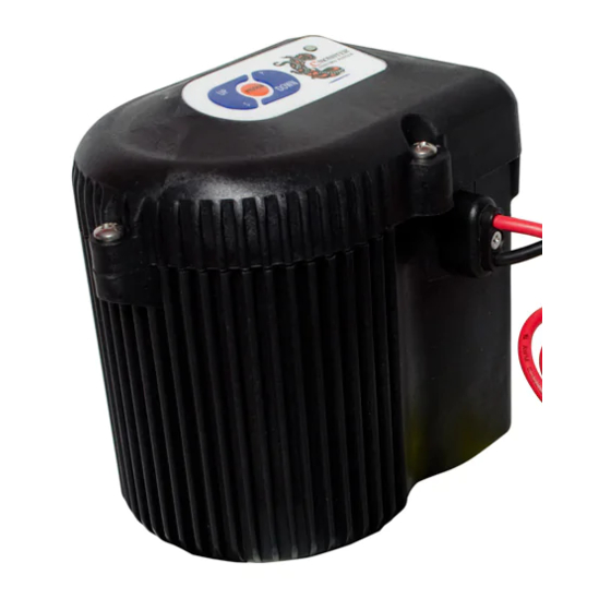
Hydraulic Pump Unit (HPU)
Hydraulic Pump Unit (HPU)
Hydraulic Pump Unit (HPU)
and the DOWN button to ensure that the anchor
PROGRAM
PROGRAM
PROGRAM
LED
LED
LED
is responding.
Hydraulic Pump Unit (HPU)
PROGRAM
For Technical Support Call 813.689.9932 option 2
For Technical Support Call 813.689.9932 option 2
For Technical Support Call 813.689.9932 option 2
Technology
Technology
Technology
MICRO Driver Unit
MICRO Driver Unit
MICRO Driver Unit
PROGRAM
PROGRAM
PROGRAM
LED
LED
LED
MICRO Driver Unit
PROGRAM
LED
LED
Advertisement

Related Manuals for Power-Pole Fob-CM1

Summary of Contents for Power-Pole Fob-CM1
- Page 1 Figure 3 PROGRAM PROGRAM To activate your warranty or find a Power-Pole Certified Warranty Center, To activate your warranty or find a Power-Pole Certified To activate your warranty or find a Power-Pole Certified To activate your warranty or find a Power-Pole Certified go to www.power-pole.com...
- Page 2 FCC Part 15.19 Warning Statement IC RSS-GEN, Sec 7.1.2 Warning Statement THIS DEVICE COMPLIES WITH PART 15 OF THE FCC RULES. ENGLISH: Under Industry Canada regulations, this OPERATION IS SUBJECT TO THE FOLLOWING TWO radio transmitter may only operate using an antenna CONDITIONS: (1) THIS DEVICE MAY NOT CAUSE HARMFUL of a type and maximum (or lesser) gain approved for INTERFERENCE, AND (2) THIS DEVICE MUST ACCEPT ANY...
Need help?
Do you have a question about the Fob-CM1 and is the answer not in the manual?
Questions and answers