
Related Manuals for Rohde & Schwarz R&S ZNL3


Summary of Contents for Rohde & Schwarz R&S ZNL3
- Page 1 www.allice.de Allice Messtechnik GmbH ® R&S ZNL/ZNLE Vector Network Analyzers User Manual (;ÜÉÐ2) 1178596602...
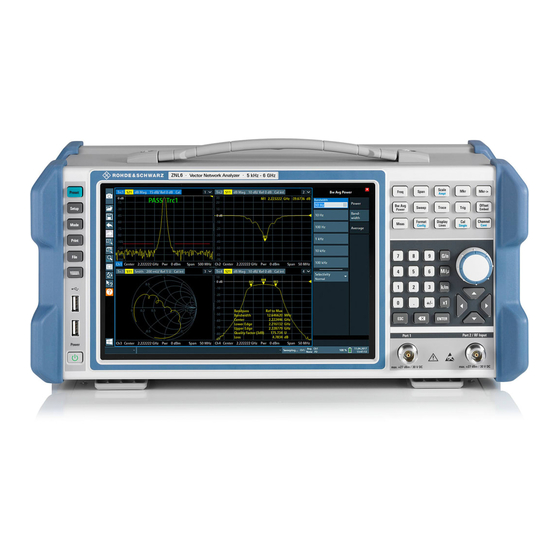
- Page 2 www.allice.de Allice Messtechnik GmbH This manual applies to the following vector network analyzer models: ● ® R&S ZNL3, 5 kHz to 3 GHz, 2 ports, N(f) connectors, order no. 1323.0012.03 ● ® R&S ZNL6, 5 kHz to 6 GHz, 2 ports, N(f) connectors, order no. 1323.0012.06 ●...
-
Page 3: Table Of Contents
www.allice.de Allice Messtechnik GmbH ® Contents R&S ZNL/ZNLE Contents 1 Preface....................11 Conventions Used in the Documentation..............11 1.1.1 Typographical Conventions................... 11 1.1.2 Conventions for Procedure Descriptions............... 11 1.1.3 Notes on Screenshots....................11 2 Safety Information................13 3 Documentation Overview..............14 Getting Started Manual....................14 User Manuals and Help....................14 Service Manual...................... - Page 4 www.allice.de Allice Messtechnik GmbH ® Contents R&S ZNL/ZNLE Trying Out the Instrument..................55 5.3.1 Performing Measurements....................56 5.3.2 Zooming into the Display....................63 5.3.3 Saving Settings......................64 5.3.4 Printing and Saving Results..................66 5.3.5 Activating Additional Channel Setups................67 5.3.6 Trying Out Spectrum Mode................... 69 5.3.7 Performing Sequential Measurements................75 Operating the Instrument...................
- Page 5 www.allice.de Allice Messtechnik GmbH ® Contents R&S ZNL/ZNLE 7.3.3 Language Settings...................... 132 7.3.4 System Configuration Settings..................133 7.3.5 Service Functions......................139 7.3.6 VNA Setup........................144 Network and Remote Settings................. 151 7.4.1 Remote Control Interfaces and Protocols..............151 7.4.2 SCPI (Standard Commands for Programmable Instruments)........158 7.4.3 VISA Libraries......................
- Page 6 www.allice.de Allice Messtechnik GmbH ® Contents R&S ZNL/ZNLE 8.5.1 Calibration Types......................243 8.5.2 Calibration Standards and Calibration Kits..............247 8.5.3 Calibration Pool......................253 8.5.4 Calibration Labels....................... 253 8.5.5 Automatic Calibration....................254 8.5.6 Parallel Calibration of Multiple Channels..............259 Offset Parameters and Embedding................. 259 8.6.1 Offset Parameters.......................
- Page 7 www.allice.de Allice Messtechnik GmbH ® Contents R&S ZNL/ZNLE 9.4.1 Power Tab........................299 9.4.2 Bandwidth Tab......................300 9.4.3 Average Tab........................ 301 Sweep Softtool......................302 9.5.1 Sweep Params Tab..................... 302 9.5.2 Sweep Type Tab......................305 9.5.3 Trigger Tab........................315 9.5.4 Sweep Control Tab......................320 Trace Softtool......................322 9.6.1 Traces Tab........................322 9.6.2...
- Page 8 www.allice.de Allice Messtechnik GmbH ® Contents R&S ZNL/ZNLE 9.9.4 Limit Test Tab......................398 9.9.5 Ripple Test Tab......................405 9.9.6 Circle Test Tab......................410 9.9.7 Display Circle Tab....................... 413 9.9.8 Horiz. Line Tab......................414 9.10 Marker Settings Softtool...................415 9.10.1 Markers Tab........................ 415 9.10.2 Marker Props Tab......................418 9.10.3 Set by Marker Tab.......................
- Page 9 www.allice.de Allice Messtechnik GmbH ® Contents R&S ZNL/ZNLE 9.14.9 Config Tab........................503 10 Command Reference................. 505 10.1 Conventions Used in SCPI Command Descriptions..........505 10.2 Common Commands....................506 10.3 Common Instrument Commands................510 10.3.1 Commands for Remote Instrument Operation............510 10.3.2 Selecting the Operating Mode and Application............
- Page 10 www.allice.de Allice Messtechnik GmbH ® Contents R&S ZNL/ZNLE 12.4 Maintenance......................977 12.4.1 Cleaning........................978 12.4.2 Storing and Packing the Instrument................978 Glossary: Frequently Used Terms............979 List of Commands................985 Index....................1001 User Manual 1178.5966.02 ─ 07...
-
Page 11: Preface
www.allice.de Allice Messtechnik GmbH ® Preface R&S ZNL/ZNLE Conventions Used in the Documentation 1 Preface This chapter provides safety-related information, an overview of the user documenta- tion and the conventions used in the documentation. 1.1 Conventions Used in the Documentation 1.1.1 Typographical Conventions The following text markers are used throughout this documentation: Convention... - Page 12 www.allice.de Allice Messtechnik GmbH ® Preface R&S ZNL/ZNLE Conventions Used in the Documentation possible interdependencies between parameters. The shown values may not represent realistic usage scenarios. The screenshots usually show a fully equipped product, that is: with all options instal- led.
-
Page 13: Safety Information
www.allice.de Allice Messtechnik GmbH ® Safety Information R&S ZNL/ZNLE 2 Safety Information The product documentation helps you use the R&S ZNL/ZNLE safely and efficiently. Follow the instructions provided here and in the printed "Basic Safety Instructions". Keep the product documentation nearby and offer it to other users. Intended use The R&S ZNL/ZNLE is intended for the development, production and verification of electronic components and devices in industrial, administrative, and laboratory environ-... -
Page 14: Documentation Overview
www.allice.de Allice Messtechnik GmbH ® Documentation Overview R&S ZNL/ZNLE Service Manual 3 Documentation Overview This section provides an overview of the R&S ZNL/ZNLE user documentation. Unless specified otherwise, you find the documents on the R&S ZNL/ZNLE product page at: www.rohde-schwarz.com/manual/ZNL or www.rohde-schwarz.com/manual/ZNLE. -
Page 15: Instrument Security Procedures
www.allice.de Allice Messtechnik GmbH ® Documentation Overview R&S ZNL/ZNLE Release Notes and Open Source Acknowledgment (OSA) https://gloris.rohde-schwarz.com/irj/portal/SearchDetailView?downloadContai- nerID=484937 ZNL service manual, ZNLE service manual 3.4 Instrument Security Procedures Deals with security issues when working with the R&S ZNL/ZNLE in secure areas. It is available for download on the Internet. -
Page 16: Application Notes, Application Cards, White Papers, Etc
www.allice.de Allice Messtechnik GmbH ® Documentation Overview R&S ZNL/ZNLE Calibration Certificate 3.8 Application Notes, Application Cards, White Papers, etc. These documents deal with special applications or background information on particu- lar topics. www.rohde-schwarz.com/application/ZNL www.rohde-schwarz.com/application/ ZNLE. 3.9 Calibration Certificate The document is available on https://gloris.rohde-schwarz.com/calcert. You need the device ID of your instrument, which you can find on a label on the rear panel. -
Page 17: Release Notes For Firmware V1.30
www.allice.de Allice Messtechnik GmbH ® Release Notes for Firmware V1.30 R&S ZNL/ZNLE Changes in Firmware V1.30 4 Release Notes for Firmware V1.30 4.1 Known Issues The following table lists the known issues and indicates since which version the issue could be observed: since FW affected applications / Function... - Page 18 www.allice.de Allice Messtechnik GmbH ® Release Notes for Firmware V1.30 R&S ZNL/ZNLE Changes in Firmware V1.30 Chapter 9.14.9, "Config Tab", on page 503. ● Continuous auto-scaling of traces "Continuous Auto Scale Trace" on page 296. ● Trace math on formatted traces See the new Chapter 9.6.3, "Math",...
- Page 19 www.allice.de Allice Messtechnik GmbH ® Release Notes for Firmware V1.30 R&S ZNL/ZNLE Changes in Firmware V1.30 ● "Low Pass Step" time domain representation (R&S ZNL-K2): DC extrapolation did only work for S-parameter traces ● Fixture measurement data were not always stored with s1p file name extension ●...
-
Page 20: Getting Started
www.allice.de Allice Messtechnik GmbH ® Getting Started R&S ZNL/ZNLE Preparing for Use 5 Getting Started 5.1 Preparing for Use ● Putting into Operation..................... 20 ● Windows Operating System..................28 ● Connecting USB Devices..................32 ● Connecting an External Monitor................34 ● Setting Up a Network (LAN) Connection..............35 ●... - Page 21 www.allice.de Allice Messtechnik GmbH ® Getting Started R&S ZNL/ZNLE Preparing for Use Risk of instrument damage due to inappropriate operating conditions An unsuitable operating site or test setup can damage the instrument and connected devices. Before switching on the instrument, observe the information on appropriate operating conditions provided in the data sheet.
- Page 22 www.allice.de Allice Messtechnik GmbH ® Getting Started R&S ZNL/ZNLE Preparing for Use Risk of instrument damage during transportation and shipment Insufficient protection against mechanical and electrostatic effects during transportation and shipment can damage the instrument. ● Always make sure that sufficient mechanical and electrostatic protection is provi- ded.
- Page 23 www.allice.de Allice Messtechnik GmbH ® Getting Started R&S ZNL/ZNLE Preparing for Use Risk of injury if feet are folded out The feet can fold in if they are not folded out completely or if the instrument is shifted. This can cause damage or injury. ●...
- Page 24 www.allice.de Allice Messtechnik GmbH ® Getting Started R&S ZNL/ZNLE Preparing for Use Risk of instrument damage due to insufficient airflow in a rack If you mount several instruments in a rack, you need an efficient ventilation concept to ensure that the instruments do not overheat. Insufficient airflow for a longer period can disturb the operation and even cause damage.
- Page 25 www.allice.de Allice Messtechnik GmbH ® Getting Started R&S ZNL/ZNLE Preparing for Use For details on the connector, refer to Chapter 5.2.2.2, "AC Power Supply Connection and Main Power Switch", on page 52. ► Connect the R&S ZNL/ZNLE to the AC power supply using the supplied power cable.
- Page 26 www.allice.de Allice Messtechnik GmbH ® Getting Started R&S ZNL/ZNLE Preparing for Use Risk of electric shock Insufficient insulation and exceeding the current limitation of external power supplies for safety extra-low DC voltage (SELV) can lead to electric shock. Be sure to meet the requirements for reinforced/double insulation in accordance with DIN/EN/IEC 61010 (UL 3111, CSA C22.2 No.
- Page 27 www.allice.de Allice Messtechnik GmbH ® Getting Started R&S ZNL/ZNLE Preparing for Use The battery pack is not charged in the factory. The battery pack must be charged before it is used the first time. A new battery pack or a battery pack which has not been used for a longer time attains full capacity after several charge/ discharge cycles.
-
Page 28: Windows Operating System
www.allice.de Allice Messtechnik GmbH ® Getting Started R&S ZNL/ZNLE Preparing for Use Risk of losing data If you switch off the running instrument using the rear panel switch or by disconnecting the power cord, and no (charged) battery is available, the instrument loses its current settings. - Page 29 www.allice.de Allice Messtechnik GmbH ® Getting Started R&S ZNL/ZNLE Preparing for Use The following program packages have been tested: ● Symantec Endpoint Security – virus-protection software ● FileShredder - for reliable deletion of files on the hard disk 5.1.2.1 Virus Protection Take appropriate steps to protect your instruments from infection.
- Page 30 www.allice.de Allice Messtechnik GmbH ® Getting Started R&S ZNL/ZNLE Preparing for Use Passwords For all default user accounts, the initial password is 894129. Note that this password is very weak, and it is recommended that you change the password for both users after initial login.
- Page 31 www.allice.de Allice Messtechnik GmbH ® Getting Started R&S ZNL/ZNLE Preparing for Use This command deactivates the automatic login function. The next time you switch on the instrument, the operating system prompts you to enter your user name and password before it starts the firmware. Adapting the automatic login function to a new password If you change the "Instrument"...
-
Page 32: Connecting Usb Devices
www.allice.de Allice Messtechnik GmbH ® Getting Started R&S ZNL/ZNLE Preparing for Use (For required settings refer to the Windows documentation and to the hardware description). 5.1.2.5 Accessing the Windows Taskbar The Windows taskbar also provides quick access to commonly used programs, for example Paint or WordPad. - Page 33 www.allice.de Allice Messtechnik GmbH ® Getting Started R&S ZNL/ZNLE Preparing for Use Connecting a keyboard The keyboard is detected automatically when it is connected. The default input lan- guage is English – US. However, you can also connect foreign language keyboards; currently the following languages are supported for the R&S ZNL/ZNLE: ●...
-
Page 34: Connecting An External Monitor
www.allice.de Allice Messtechnik GmbH ® Getting Started R&S ZNL/ZNLE Preparing for Use 5.1.4 Connecting an External Monitor You can connect an external monitor (or projector) to the "DVI" connector on the rear panel of the R&S ZNL/ZNLE (see also Chapter 5.2.2.6, "DVI", on page 53). -
Page 35: Setting Up A Network (Lan) Connection
www.allice.de Allice Messtechnik GmbH ® Getting Started R&S ZNL/ZNLE Preparing for Use 8. Select "OK" if the settings are suitable. Fixing a wrong touchscreen mapping For instruments that are equipped with a system image version < 0.8, the touchscreen function is erroneously mapped to the external monitor by default. This mismatch is particularly inconvenient in extended display mode, where touch gestures on the instrument screen actually operate on the external screen. - Page 36 www.allice.de Allice Messtechnik GmbH ® Getting Started R&S ZNL/ZNLE Preparing for Use you the appropriate rights and adapted the Windows firewall configuration, you can use the interface, for example: ● To transfer data between a controlling device and the test device, e.g. to run a remote control program.
- Page 37 www.allice.de Allice Messtechnik GmbH ® Getting Started R&S ZNL/ZNLE Preparing for Use Risk of network failure Consult your network administrator before performing the following tasks: ● Connecting the instrument to the network ● Configuring the network ● Changing IP addresses Errors can affect the entire network.
- Page 38 www.allice.de Allice Messtechnik GmbH ® Getting Started R&S ZNL/ZNLE Preparing for Use 3. Select the "Network" tab. 4. In the "Network + Remote" dialog, toggle the "DHCP On/Off" setting to the required mode. If DHCP is "Off", you must enter the IP address manually, as described in the fol- lowing steps.
- Page 39 www.allice.de Allice Messtechnik GmbH ® Getting Started R&S ZNL/ZNLE Preparing for Use 4. In the "Ethernet Status" dialog box, select the "Properties" button. The items used by the LAN connection are displayed. User Manual 1178.5966.02 ─ 07...
- Page 40 www.allice.de Allice Messtechnik GmbH ® Getting Started R&S ZNL/ZNLE Preparing for Use 5. Tap the entry named "Internet Protocol Version 4 (TCP/IPv4)" to highlight it. 6. Select the "Properties" button. 7. On the "General" tab, select "Use the following DNS server addresses" and enter your own DNS addresses.
-
Page 41: Configuring The Initial Instrument Settings
www.allice.de Allice Messtechnik GmbH ® Getting Started R&S ZNL/ZNLE Preparing for Use <Type><variant>-<serial_number> The serial number can be found on the rear panel of the instrument. It is the third part of the device ID printed on the bar code sticker: For example, ZNL3-123456 To change the computer name 1. -
Page 42: Instrument Tour
www.allice.de Allice Messtechnik GmbH ® Getting Started R&S ZNL/ZNLE Instrument Tour 2. Press the "Language" softkey. 3. Select the required language. All text elements of the R&S ZNL/ZNLE user interface are displayed in the selected language. Texts in standard Windows dialog boxes are displayed in the language defined in the regional settings of the Windows operating system. - Page 43 www.allice.de Allice Messtechnik GmbH ® Getting Started R&S ZNL/ZNLE Instrument Tour Figure 5-1: Front panel view 1 = Power key 2 = USB (2.0) connectors 3 = System keys 4 = Touchscreen 5 = Function keys 6 = Keypad 7 = Navigation controls 8 = Port 1 9 = Port 2 / RF Input 50 Ω...
- Page 44 www.allice.de Allice Messtechnik GmbH ® Getting Started R&S ZNL/ZNLE Instrument Tour Figure 5-2: Touchscreen elements 1 = Toolbar with standard application functions, e.g. print, save/open file etc. 2 = Tabs for individual channel setups 3 = Softtool panel (a.k.a. softkey bar) 4 = Window title bar with diagram-specific (trace) information 5 = Measurement results (diagram) area 6 = Channel list...
- Page 45 www.allice.de Allice Messtechnik GmbH ® Getting Started R&S ZNL/ZNLE Instrument Tour For details on touchscreen gestures see Chapter 5.4.4, "Touchscreen Gestures", on page 82. 5.2.1.2 Power Key The [Power] key is located on the lower left corner of the front panel. It starts up and shuts down the instrument.
- Page 46 www.allice.de Allice Messtechnik GmbH ® Getting Started R&S ZNL/ZNLE Instrument Tour 5.2.1.5 Function Keys Function keys provide access to the most common measurement settings and func- tions. A detailed description of the corresponding functions is provided in the User Manual. The labels indicated in italics (blue font color on the instrument) apply to the optional Spectrum mode only.
- Page 47 www.allice.de Allice Messtechnik GmbH ® Getting Started R&S ZNL/ZNLE Instrument Tour Function key Assigned functions VNA mode SA mode (R&S ZNL only) [Offset Embed] Contains functions for deembedding/ Performs a peak search for active embedding the DUT from/into physical/ marker. If no marker is active, normal virtual (matching) networks placed marker 1 is activated and the peak between the calibrated reference plane...
- Page 48 www.allice.de Allice Messtechnik GmbH ® Getting Started R&S ZNL/ZNLE Instrument Tour Type of key Description If an alphanumeric entry has already been started, this key deletes the character to the left of the cursor. (BACKSPACE) ● [ENTER] Concludes the entry of dimensionless entries. The new value is accepted.
- Page 49 www.allice.de Allice Messtechnik GmbH ® Getting Started R&S ZNL/ZNLE Instrument Tour Arrow Left/Arrow Right Keys The <arrow left> or <arrow right> keys do the following: ● In an alphanumeric edit dialog box, move the cursor. ● In a list, scroll forward and backward through the list entries. ●...
-
Page 50: Rear Panel View
www.allice.de Allice Messtechnik GmbH ® Getting Started R&S ZNL/ZNLE Instrument Tour Risk of instrument damage Do not overload the input. For maximum allowed values, see the data sheet. A DC input voltage of 50 V must never be exceeded. 5.2.2 Rear Panel View This figure shows the rear panel view of the R&S ZNL/ZNLE. - Page 51 www.allice.de Allice Messtechnik GmbH ® Getting Started R&S ZNL/ZNLE Instrument Tour Figure 5-4: Rear panel view R&S ZNLE 1 = AC Power Supply Connection and Main Power Switch 2 = GPIB ("IEC") interface 3 = Reference clock connectors 4 = Trigger input connector 5 = "DVI"...
- Page 52 www.allice.de Allice Messtechnik GmbH ® Getting Started R&S ZNL/ZNLE Instrument Tour Risk of electric shock! If external power supply units for supplying safety extra-low DC voltage (SELV) to the instrument are used, the requirements for reinforced/double insulation in accordance with DIN/EN/IEC 61010 (UL 3111, CSA C22.2 No. 1010.1) or DIN/EN/IEC 60950 (UL 1950, CSA C22.2 No.
- Page 53 www.allice.de Allice Messtechnik GmbH ® Getting Started R&S ZNL/ZNLE Instrument Tour Connector Reference signal Usage Ref. In 10 MHz To provide an external reference signal on the R&S ZNL/ZNLE. 10 dBm Ref. Out 10 MHz To provide the internal reference signal from the R&S ZNL/ZNLE to another device continuously.
- Page 54 www.allice.de Allice Messtechnik GmbH ® Getting Started R&S ZNL/ZNLE Instrument Tour 5.2.2.10 Aux. Port A 25-pole D-Sub connector used as an input and output for low-voltage TTL control signals. Can either be used as VNA User Port (max. 3.3 V) or SA Aux. Port (max. 5 V). At the FW GUI this can be set via [Setup] >...
-
Page 55: Trying Out The Instrument
www.allice.de Allice Messtechnik GmbH ® Getting Started R&S ZNL/ZNLE Trying Out the Instrument 5.2.2.12 Headphones Connector The Spectrum Mode provides demodulators for AM, FM and PM signals, which can be routed to the headphone connector. With headphones or an external loudspeaker con- nected to the 3.5 mm headphone socket the displayed signal can be identified acousti- cally. -
Page 56: Performing Measurements
www.allice.de Allice Messtechnik GmbH ® Getting Started R&S ZNL/ZNLE Trying Out the Instrument Prerequisites ● The instrument is set up, connected to the mains system, and started up as descri- bed in Chapter 5.1, "Preparing for Use", on page 20. ●... - Page 57 www.allice.de Allice Messtechnik GmbH ® Getting Started R&S ZNL/ZNLE Trying Out the Instrument output port. The trace settings allow you to select the measured quantities and display formats, depending on what you want to learn from the data. A minimum of two ana- lyzer test ports are required for transmission measurements.
- Page 58 www.allice.de Allice Messtechnik GmbH ® Getting Started R&S ZNL/ZNLE Trying Out the Instrument Select [Trace] and use the control elements in the "Traces" softtool tab if you wish to create additional traces and diagrams. Selecting the Sweep Range and Other Parameters After a system preset the display shows a diagram with a dB magnitude scale, and the S-parameter S is selected as a measured quantity.
- Page 59 www.allice.de Allice Messtechnik GmbH ® Getting Started R&S ZNL/ZNLE Trying Out the Instrument ing cables between the analyzer ports and the DUT introduce an attenuation and a phase shift of the waves. Both effects impair the accuracy of the S-parameter mea- surement.
- Page 60 www.allice.de Allice Messtechnik GmbH ® Getting Started R&S ZNL/ZNLE Trying Out the Instrument 6. The "Calibration" dock widget indicates the standard measurements that make up a "Trans Norm" calibration. Select "Through (mm)" to initiate the measurement of the connected Through stan- dard.
- Page 61 www.allice.de Allice Messtechnik GmbH ® Getting Started R&S ZNL/ZNLE Trying Out the Instrument 7. Select "Apply" to close the wizard and apply the system error correction to the cur- rent channel. A "Cal" label appears in the trace list. To proceed with the measurement, remove the Through standard and connect the DUT again.
- Page 62 www.allice.de Allice Messtechnik GmbH ® Getting Started R&S ZNL/ZNLE Trying Out the Instrument Refer to Chapter 8.2.3, "Trace Formats", on page 208 to learn more about the diagram properties. 5.3.1.2 Reflection S-Parameter Measurement In a reflection measurement, the analyzer transmits a stimulus signal to the input port of the device under test (DUT) and measures the reflected wave.
-
Page 63: Zooming Into The Display
www.allice.de Allice Messtechnik GmbH ® Getting Started R&S ZNL/ZNLE Trying Out the Instrument ● The analyzer provides special calibration types for reflection measurements. Use the calibration wizard and select an appropriate type. The full 2-port calibration TOSM corrects the system errors for all transmission and reflection S-parameters. -
Page 64: Saving Settings
www.allice.de Allice Messtechnik GmbH ® Getting Started R&S ZNL/ZNLE Trying Out the Instrument Figure 5-6: Zoomed display around a peak 5.3.3 Saving Settings To restore the results of our measurements later, we will store the instrument settings to a file. To save the instrument settings to a file 1. - Page 65 www.allice.de Allice Messtechnik GmbH ® Getting Started R&S ZNL/ZNLE Trying Out the Instrument Figure 5-7: Saving the instrument settings to a file 4. Tap the "Save" button. The file MyMultiViewSetup.dfl is stored in the default directory C:\Users\Public\Documents\Rohde-Schwarz\ZNL\user. To load stored instrument settings You can restore the settings to the instrument at any time using the settings file.
-
Page 66: Printing And Saving Results
www.allice.de Allice Messtechnik GmbH ® Getting Started R&S ZNL/ZNLE Trying Out the Instrument 5.3.4 Printing and Saving Results Finally, after a successful measurement, we will document our results. First we will export the numeric trace data, then we will create a screenshot of the graphical display. To export the trace data 1. -
Page 67: Activating Additional Channel Setups
www.allice.de Allice Messtechnik GmbH ® Getting Started R&S ZNL/ZNLE Trying Out the Instrument 5.3.5 Activating Additional Channel Setups The R&S ZNL/ZNLE features multiple channel setups, i.e. you can define several mea- surement configurations in parallel and then switch between the channel setups auto- matically to perform the measurements sequentially. - Page 68 www.allice.de Allice Messtechnik GmbH ® Getting Started R&S ZNL/ZNLE Trying Out the Instrument d) Drag the "Real/Imag (I/Q)" icon from the evaluation bar to the SmartGrid. Figure 5-9: Inserting a Real/Imag diagram for I/Q analysis e) Close the SmartGrid mode. The "IQ Analyzer"...
-
Page 69: Trying Out Spectrum Mode
www.allice.de Allice Messtechnik GmbH ® Getting Started R&S ZNL/ZNLE Trying Out the Instrument Figure 5-10: The "MultiView" tab 5.3.6 Trying Out Spectrum Mode If the "Spectrum Analysis" option B1 for the R&S ZNL is installed, you can use the instrument to perform spectrum measurements. The following chapters describe some basic tasks in Spectrum mode. - Page 70 www.allice.de Allice Messtechnik GmbH ® Getting Started R&S ZNL/ZNLE Trying Out the Instrument 4. Tap the "Service + Support" softkey. 5. Tap the "Calibration Signal" tab. 6. Tap the "Calibration Frequency RF" option. Leave the frequency at the default 50 MHz. 7.
- Page 71 www.allice.de Allice Messtechnik GmbH ® Getting Started R&S ZNL/ZNLE Trying Out the Instrument 3. Set the reference level to -25 dBm: a) In the configuration "Overview", tap the "Amplitude" button. b) In the "Value" field of the "Amplitude" dialog box, enter -25 dBm. The display of the calibration signal is now improved.
- Page 72 www.allice.de Allice Messtechnik GmbH ® Getting Started R&S ZNL/ZNLE Trying Out the Instrument Drag the "Spectrogram" icon from the evaluation bar to the diagram area. The blue area indicates that the new diagram would replace the previous spectrum display. Since we do not want to replace the spectrum, drag the icon to the lower half of the display to add an additional window instead.
- Page 73 www.allice.de Allice Messtechnik GmbH ® Getting Started R&S ZNL/ZNLE Trying Out the Instrument Figure 5-14: Spectrogram of the calibration signal 5.3.6.3 Setting and Moving a Marker Markers are useful to determine the position of particular effects in the trace. The most common use is to determine a peak, which is the default setting when you activate a marker.
- Page 74 www.allice.de Allice Messtechnik GmbH ® Getting Started R&S ZNL/ZNLE Trying Out the Instrument 6. Now you can move the marker by tapping and dragging it to a different position. The current position is indicated by a dotted blue line. Notice how the position and value change in the marker area of the diagram.
-
Page 75: Performing Sequential Measurements
www.allice.de Allice Messtechnik GmbH ® Getting Started R&S ZNL/ZNLE Trying Out the Instrument 6. To obtain a more conclusive peak list that does not contain noise peaks, for exam- ple, define a threshold that is higher than the noise floor: a) Press the [MKR] key on the front panel. -
Page 76: Operating The Instrument
www.allice.de Allice Messtechnik GmbH ® Getting Started R&S ZNL/ZNLE Operating the Instrument Figure 5-16: "MultiView" tab with active Sequencer Figure 5-16, the "Spectrum 2" measurement is currently active (indicated by the "channel active" icon in the tab label). 3. Stop the Sequencer by tapping the "Sequencer" softkey again. 5.4 Operating the Instrument This chapter provides an overview on how to work with the R&S ZNL/ZNLE. -
Page 77: Understanding The Display Information (Vna Mode)
www.allice.de Allice Messtechnik GmbH ® Getting Started R&S ZNL/ZNLE Operating the Instrument ● Understanding the Display Information (VNA Mode)..........77 ● Accessing the Functionality..................78 ● Entering Data......................81 ● Touchscreen Gestures.................... 82 ● Getting Help......................85 ● Remote Control....................... 87 5.4.1 Understanding the Display Information (VNA Mode) The following figure shows a measurement diagram in VNA mode. -
Page 78: Accessing The Functionality
www.allice.de Allice Messtechnik GmbH ® Getting Started R&S ZNL/ZNLE Operating the Instrument 1 = Trace name 2 = Measured parameter 3 = Trace format 4 = Scale per division 5 = Reference value Diagram footer For each parameter diagram, a window is displayed with the following information in the footer: 1 = Channel 2 = Center frequency... - Page 79 www.allice.de Allice Messtechnik GmbH ® Getting Started R&S ZNL/ZNLE Operating the Instrument 5.4.2.1 Toolbar Standard functions can be performed via the icons in the toolbar on the left side of the screen. You can hide the toolbar display, e.g. when using remote control, to enlarge the display area for the measurement results ("Setup"...
- Page 80 www.allice.de Allice Messtechnik GmbH ® Getting Started R&S ZNL/ZNLE Operating the Instrument 5.4.2.3 Context Menus Several items in the diagram area have context menus (for example markers, traces or the channel bar). If you right-click on one of these items (or tap it for about 1 second), a menu is displayed which contains the same functions as the corresponding softkey.
-
Page 81: Entering Data
www.allice.de Allice Messtechnik GmbH ® Getting Started R&S ZNL/ZNLE Operating the Instrument When you press this key, the display switches between the following options: ● Keyboard displayed at the top of the screen ● Keyboard displayed at the bottom of the screen ●... -
Page 82: Touchscreen Gestures
www.allice.de Allice Messtechnik GmbH ® Getting Started R&S ZNL/ZNLE Operating the Instrument 3. If the parameter does not require a unit, confirm the entered value by pressing the [ENTER] key or any of the unit keys. The editing line is highlighted to confirm the entry. Entering Alphanumeric Parameters If a field requires alphanumeric input, you can use the on-screen keyboard to enter numbers and (special) characters (see... - Page 83 www.allice.de Allice Messtechnik GmbH ® Getting Started R&S ZNL/ZNLE Operating the Instrument Double-tapping Tap the screen twice, in quick succession. Double-tap a diagram or the window title bar to maximize a window in the display, or to restore the original size. Dragging Move your finger from one position to another on the display, keeping your finger on the display the whole time.
- Page 84 www.allice.de Allice Messtechnik GmbH ® Getting Started R&S ZNL/ZNLE Operating the Instrument Figure 5-21: Spreading Touch gestures in diagrams change measurement settings When you change the display using touch gestures, the corresponding measurement settings are adapted. This is different to selecting an area on the screen in zoom mode, where merely the resolution of the displayed trace points is changed temporarily (graphical zoom).
-
Page 85: Getting Help
www.allice.de Allice Messtechnik GmbH ® Getting Started R&S ZNL/ZNLE Operating the Instrument 5.4.5 Getting Help If any questions or problems concerning the R&S ZNL/ZNLE arise, an extensive online help system is provided on the instrument and can be consulted at any time. The help system is context-sensitive and provides information specifically for the current opera- tion or setting to be performed. - Page 86 www.allice.de Allice Messtechnik GmbH ® Getting Started R&S ZNL/ZNLE Operating the Instrument The Help toolbar provides some buttons: ● To browse the topics in the order of the table of contents: Up arrow = previous topic, Down arrow = next topic ●...
-
Page 87: Remote Control
www.allice.de Allice Messtechnik GmbH ® Getting Started R&S ZNL/ZNLE Operating the Instrument 5.4.6 Remote Control In addition to working with the R&S ZNL/ZNLE interactively, located directly at the instrument, it is also possible to operate and control it from a remote PC. Various meth- ods for remote control are supported: ●... - Page 88 www.allice.de Allice Messtechnik GmbH ® Getting Started R&S ZNL/ZNLE Operating the Instrument 5.4.6.3 Connecting a PC via the GPIB Interface You can connect a PC to the R&S ZNL/ZNLE via the GPIB interface to send remote commands to control and operate the instrument. You can configure the GPIB address and the ID response string.
-
Page 89: Operating Modes, Applications, Channel Setups, And Result Displays
www.allice.de Allice Messtechnik GmbH ® Operating Modes, Applications, Channel Setups, and Result Displays R&S ZNL/ZNLE 6 Operating Modes, Applications, Channel Setups, and Result Displays If the "Spectrum Analysis" hardware option B1 is installed, the R&S ZNL is actually two instruments in one: a vector network analyzer (VNA) and a spectrum analyzer (SA). The R&S ZNL integrates the functionality of the two as separate operating modes in one instrument. -
Page 90: Available Applications
www.allice.de Allice Messtechnik GmbH ® Operating Modes, Applications, Channel Setups, and Result Displays R&S ZNL/ZNLE Available Applications 6.1 Available Applications Access: [MODE] Without the spectrum analysis hardware option B1, the R&S ZNL only provides the application. ● The "Spectrum analysis" hardware option adds the Spectrum I/Q Analyzer applications. -
Page 91: R&S Multiview
www.allice.de Allice Messtechnik GmbH ® Operating Modes, Applications, Channel Setups, and Result Displays R&S ZNL/ZNLE R&S MultiView The "I/Q Analyzer" application requires a R&S ZNL equipped with the "Spectrum Analysis" hardware option B1. This option is not available for the R&S ZNLE. The "I/Q Analyzer"... -
Page 92: Defining Channel Setups
www.allice.de Allice Messtechnik GmbH ® Operating Modes, Applications, Channel Setups, and Result Displays R&S ZNL/ZNLE Defining Channel Setups 6.3 Defining Channel Setups Access: [MODE] For a R&S ZNL with spectrum analysis option B1, the startup/preset channel setup is determined by the Preset Mode. - Page 93 www.allice.de Allice Messtechnik GmbH ® Operating Modes, Applications, Channel Setups, and Result Displays R&S ZNL/ZNLE Defining Channel Setups Figure 6-1: Defining Channel Setups (R&S ZNL with R&S ZNL-B1) Switching between channel setups When you switch to a new channel setup, a set of parameters is passed on from the current channel setup to the new one: ●...
-
Page 94: Running A Sequence Of Measurements
www.allice.de Allice Messtechnik GmbH ® Operating Modes, Applications, Channel Setups, and Result Displays R&S ZNL/ZNLE Running a Sequence of Measurements Note: The channel setups are labeled with the application name. If that name already exists, a sequential number is added. You can change the name of the channel setup by double-tapping the name in the channel setup bar and entering a new name. - Page 95 www.allice.de Allice Messtechnik GmbH ® Operating Modes, Applications, Channel Setups, and Result Displays R&S ZNL/ZNLE Running a Sequence of Measurements For each individual measurement, the sweep count is considered. Thus, each mea- surement may consist of several sweeps. The currently active measurement is indica- ted by a symbol in the tab label.
- Page 96 www.allice.de Allice Messtechnik GmbH ® Operating Modes, Applications, Channel Setups, and Result Displays R&S ZNL/ZNLE Running a Sequence of Measurements Example: Sequencer procedure Assume the following active channel setup definition: Tab name Application Sweep mode Sweep count Cont. Sweep Spectrum Spectrum Cont.
-
Page 97: Sequencer Settings
www.allice.de Allice Messtechnik GmbH ® Operating Modes, Applications, Channel Setups, and Result Displays R&S ZNL/ZNLE Running a Sequence of Measurements RUN SINGLE/RUN CONT and Single Sweep/Sweep Continuous keys While the Sequencer is active, the [RUN SINGLE] and [RUN CONT] keys control the Sequencer, not individual sweeps. - Page 98 www.allice.de Allice Messtechnik GmbH ® Operating Modes, Applications, Channel Setups, and Result Displays R&S ZNL/ZNLE Running a Sequence of Measurements 1. Configure a channel setup for each measurement configuration as required, includ- ing the sweep mode. 2. In the toolbar, select the "Sequencer" icon. The "Sequencer"...
-
Page 99: Common Instrument Functions
www.allice.de Allice Messtechnik GmbH ® Common Instrument Functions R&S ZNL/ZNLE Toolbar Functions 7 Common Instrument Functions Some settings and functions are available throughout the instrument, regardless of the currently active application. These settings and functions are described here, and are not repeated for each application. -
Page 100: Data Management
www.allice.de Allice Messtechnik GmbH ® Common Instrument Functions R&S ZNL/ZNLE Data Management Undo Reverts last operation, i.e. the status before the previous action is retrieved. The undo function is useful, for example, if you are performing a zero span measure- ment with several markers and a limit line defined and accidentally select a different measurement. -
Page 101: Restoring The Default Instrument Configuration (Preset)
www.allice.de Allice Messtechnik GmbH ® Common Instrument Functions R&S ZNL/ZNLE Data Management Chapter 7.2.2, "Storing and Recalling Instrument Settings and Measurement Data", on page 102. ● Hardcopy functions can be easily accessed via the [Print] system key. Chapter 7.2.3, "Creating Screenshots of Current Measurement Results and Settings", on page 111. -
Page 102: Storing And Recalling Instrument Settings And Measurement Data
www.allice.de Allice Messtechnik GmbH ® Common Instrument Functions R&S ZNL/ZNLE Data Management To restore the default configuration for a single channel setup The default measurement settings can also be reset for an individual channel setup only, rather than resetting the entire instrument. ►... - Page 103 www.allice.de Allice Messtechnik GmbH ® Common Instrument Functions R&S ZNL/ZNLE Data Management ● Quick Save/Quick Recall..................103 ● Configurable Storage and Recall................105 ● How to Save and Load Instrument Settings............109 7.2.2.1 Quick Save/Quick Recall The Quick Save and Quick Recall functions allow you to store instrument settings or channel setups very easily and quickly in one step.
- Page 104 www.allice.de Allice Messtechnik GmbH ® Common Instrument Functions R&S ZNL/ZNLE Data Management QuickSave 1 / ... / QuickSave 10................104 Storage Type (Save only)....................104 Recall.......................... 104 QuickSave 1 / ... / QuickSave 10 Selects one of the save sets to store the current settings in or to be recalled. At the time of storage, the "QuickSave 1 / ...
- Page 105 www.allice.de Allice Messtechnik GmbH ® Common Instrument Functions R&S ZNL/ZNLE Data Management Note: After you use the "Recall" function, the history of previous actions is deleted, i.e. any actions performed previously cannot be undone or redone using the [UNDO/ REDO] keys. Remote command: on page 526 MMEMory:LOAD:STATe...
- Page 106 www.allice.de Allice Messtechnik GmbH ® Common Instrument Functions R&S ZNL/ZNLE Data Management Selecting Storage Location - Drive/ Path/ Files............106 File name........................106 Comment........................106 File Type ........................107 Items:.......................... 107 Save File........................107 Recall in New Channel / Recall in Current Channel............107 Selecting Storage Location - Drive/ Path/ Files Select the storage location of the file on the instrument or an external drive.
- Page 107 www.allice.de Allice Messtechnik GmbH ® Common Instrument Functions R&S ZNL/ZNLE Data Management File Type Determines whether the global instrument settings with all "Channel"s are stored or recalled, or the current "Channel" settings only. Items: Defines which data and settings are stored or are recalled. Depending on the "File Type"...
- Page 108 www.allice.de Allice Messtechnik GmbH ® Common Instrument Functions R&S ZNL/ZNLE Data Management Startup Recall......................108 Selecting Storage Location - Drive/ Path/ Files............108 File name........................108 Comment........................109 Startup Recall Activates or deactivates the startup recall function. If activated, the settings stored in the selected file are loaded each time the instrument is started or preset.
- Page 109 www.allice.de Allice Messtechnik GmbH ® Common Instrument Functions R&S ZNL/ZNLE Data Management Comment An optional description for the data file. A maximum of 60 characters can be displayed. Remote command: on page 521 MMEMory:COMMent 7.2.2.3 How to Save and Load Instrument Settings Instrument settings can be saved to a file and loaded again later, so that you can repeat the measurement with the same settings.
- Page 110 www.allice.de Allice Messtechnik GmbH ® Common Instrument Functions R&S ZNL/ZNLE Data Management 7. Select "Save". A file with the defined name and path and the extension .dfl is created. If you make any changes to the settings after storing the configuration file, remember to save the settings again.
-
Page 111: Creating Screenshots Of Current Measurement Results And Settings
www.allice.de Allice Messtechnik GmbH ® Common Instrument Functions R&S ZNL/ZNLE Data Management Now when you press the [PRESET] key or reboot the instrument, the defined set- tings will be restored. 6. To restore the factory preset settings, set "Startup Recall" to "Off". 7.2.3 Creating Screenshots of Current Measurement Results and Set- tings To document the graphical results and the most important settings for the currently per-... - Page 112 www.allice.de Allice Messtechnik GmbH ® Common Instrument Functions R&S ZNL/ZNLE Data Management Print Screenshot......................113 Print Multiple Windows....................113 Comment........................113 Print Logo........................113 Print Page Count......................113 Print Dialog........................113 Print Date and Time.....................114 User Manual 1178.5966.02 ─ 07...
- Page 113 www.allice.de Allice Messtechnik GmbH ® Common Instrument Functions R&S ZNL/ZNLE Data Management Print Screenshot Selects all measurement results displayed on the screen for the current channel setup (or "MultiView" ): diagrams, traces, markers, marker lists, limit lines, etc., including the channel bar and status bar, for printout on a single page.
- Page 114 www.allice.de Allice Messtechnik GmbH ® Common Instrument Functions R&S ZNL/ZNLE Data Management This setting is only available if Print Screenshot is selected. Print Date and Time Includes or removes the current date and time at the bottom of the printout. Remote command: on page 538 HCOPy:TDSTamp:STATe<device>...
- Page 115 www.allice.de Allice Messtechnik GmbH ® Common Instrument Functions R&S ZNL/ZNLE Data Management Zoom In / Zoom Out....................115 Page........................115 Zoom 1:1........................115 Page Up / Page Down....................115 Print..........................115 Zoom In / Zoom Out Zooms into (enlarges) or zooms out of (decreases) the preview display. Note that the zoom functions affect only the preview, not the printout itself.
- Page 116 www.allice.de Allice Messtechnik GmbH ® Common Instrument Functions R&S ZNL/ZNLE Data Management Destination........................116 Suppress File Name Dialog..................117 Printer Name....................... 117 Print to file........................117 Install Printer........................117 Destination Defines the medium to which the printout is output. User Manual 1178.5966.02 ─ 07...
- Page 117 www.allice.de Allice Messtechnik GmbH ® Common Instrument Functions R&S ZNL/ZNLE Data Management "File" Stores the printout to a file in the selected format. The filename is queried at the time of storage, or a default name is used (see Sup- press File Name Dialog).
- Page 118 www.allice.de Allice Messtechnik GmbH ® Common Instrument Functions R&S ZNL/ZNLE Data Management Page Setup Access: "Print" > "Print Config" > "Page Setup" tab Page settings are only available when printing on a printer or to a PDF file (see "Desti- nation"...
- Page 119 www.allice.de Allice Messtechnik GmbH ® Common Instrument Functions R&S ZNL/ZNLE Data Management Scaling Determines the scaling of the windows in the printout if Print Multiple Windows is active (see "Print Content Settings" on page 111). If more than one window is printed on one page (see Windows Per Page), each win- dow is printed in equal size.
- Page 120 www.allice.de Allice Messtechnik GmbH ® Common Instrument Functions R&S ZNL/ZNLE Data Management The settings provided here are identical to those in the "Print Colors" section of the "Display" > "Theme + Color" dialog box. "Print Colors" on page 129. 7.2.3.2 How to Store or Print Screenshots of the Display The measurement results displayed on the screen can be printed or stored to a file very easily.
- Page 121 www.allice.de Allice Messtechnik GmbH ® Common Instrument Functions R&S ZNL/ZNLE Data Management a) By default, "Optimized Colors" are used to improve the visibility of the colors. The background is always printed in white and the grid in black. For a printout that reflects exactly what you see on the screen, select "Screen Colors (Screenshot)".
-
Page 122: General Instrument Setup
www.allice.de Allice Messtechnik GmbH ® Common Instrument Functions R&S ZNL/ZNLE General Instrument Setup c) Check the "Print Preview" to make sure all relevant elements of the display are visible. 8. In the "Color" tab, define the colors to be used for the printout. a) By default, "Optimized Colors"... -
Page 123: Display Settings
www.allice.de Allice Messtechnik GmbH ® Common Instrument Functions R&S ZNL/ZNLE General Instrument Setup The R&S ZNL/ZNLE can use the internal reference source or an external reference source as the frequency standard for all internal oscillators. A 10 MHz crystal oscillator is used as the internal reference source. - Page 124 www.allice.de Allice Messtechnik GmbH ® Common Instrument Functions R&S ZNL/ZNLE General Instrument Setup Deactivating and Activating the Touchscreen............. 124 Display Update Rate....................124 Set Date and Time ..................... 124 Date and Time Format ....................125 Background Lighting....................125 Deactivating and Activating the Touchscreen The touchscreen function can be deactivated, e.g.
- Page 125 www.allice.de Allice Messtechnik GmbH ® Common Instrument Functions R&S ZNL/ZNLE General Instrument Setup Date and Time Format Switches the time and date display on the screen between US and German (DE) for- mat. Remote command: on page 550 DISPlay[:WINDow<n>]:TIME:FORMat Background Lighting Changes the brightness of the display in eight steps.
- Page 126 www.allice.de Allice Messtechnik GmbH ® Common Instrument Functions R&S ZNL/ZNLE General Instrument Setup Channel Bar........................ 126 Diagram Footer (Annotation)..................126 Date and Time......................127 Front Panel........................127 Mini Front Panel......................127 Toolbar The toolbar provides access to frequently used functions via icons at the top of the screen.
- Page 127 www.allice.de Allice Messtechnik GmbH ® Common Instrument Functions R&S ZNL/ZNLE General Instrument Setup Remote command: on page 549 DISPlay:ANNotation:FREQuency Date and Time The date and time display can be switched off independently of the status bar. You can set the current date and time and configure the display format in the "General" tab of the "Display"...
- Page 128 www.allice.de Allice Messtechnik GmbH ® Common Instrument Functions R&S ZNL/ZNLE General Instrument Setup Note: You can also activate the mini front panel using the key combination [ALT + m] (be aware of the keyboard language defined in the operating system!). That is useful when you are working from a remote PC and the front panel function is not active.
- Page 129 www.allice.de Allice Messtechnik GmbH ® Common Instrument Functions R&S ZNL/ZNLE General Instrument Setup Theme......................... 129 Print Colors......................... 129 Showing Print Colors on Display.................130 Theme The theme defines the colors and style used to display softkeys and other screen objects. The default theme is "IndustrialDark". Remote command: on page 552 DISPlay:THEMe:SELect...
- Page 130 www.allice.de Allice Messtechnik GmbH ® Common Instrument Functions R&S ZNL/ZNLE General Instrument Setup Showing Print Colors on Display Temporarily shows the currently selected print colors on the screen display. This func- tion can be used as a preview for printing. External Monitor Settings Access: [Setup] >...
- Page 131 www.allice.de Allice Messtechnik GmbH ® Common Instrument Functions R&S ZNL/ZNLE General Instrument Setup ● Select a predefined set of colors for screen display. ● Select "User Defined Colors" to configure the color set yourself. 4. In the "Print Colors" area, do one of the following: ●...
-
Page 132: Language Settings
www.allice.de Allice Messtechnik GmbH ® Common Instrument Functions R&S ZNL/ZNLE General Instrument Setup Icon Function Turn left Enter Turn right Mini front panel The mini front panel provides only the keys on the touchscreen, to operate the R&S ZNL/ZNLE via an external monitor or remote desktop. By default, the "Auto close"... -
Page 133: System Configuration Settings
www.allice.de Allice Messtechnik GmbH ® Common Instrument Functions R&S ZNL/ZNLE General Instrument Setup 7.3.4 System Configuration Settings Access: [Setup] > "System Configuration" ● Hardware Information....................133 ● Information on Versions and Options..............133 ● System Messages....................135 ● Firmware Updates....................136 ● General Configuration Settings................ - Page 134 www.allice.de Allice Messtechnik GmbH ® Common Instrument Functions R&S ZNL/ZNLE General Instrument Setup Expired option licenses If an option is about to expire, a message box is displayed to inform you. You can then use the "Install Option" function to enter a new license key. If an option has already expired, a message box appears for you to confirm.
- Page 135 www.allice.de Allice Messtechnik GmbH ® Common Instrument Functions R&S ZNL/ZNLE General Instrument Setup Install Option Opens an edit dialog box to enter the license key for the option that you want to install. Install Option by XML Opens a file selection dialog box to install an additional option to the R&S ZNL/ZNLE using an XML file.
- Page 136 www.allice.de Allice Messtechnik GmbH ® Common Instrument Functions R&S ZNL/ZNLE General Instrument Setup Remote command: on page 558 SYSTem:ERRor:LIST? 7.3.4.4 Firmware Updates Access: [Setup] > "System Configuration" > "Firmware Update" During instrument start, the installed hardware is checked against the current firmware version to ensure the hardware is supported.
- Page 137 www.allice.de Allice Messtechnik GmbH ® Common Instrument Functions R&S ZNL/ZNLE General Instrument Setup Enter the name or browse for the firmware installation file and press the "Install" but- ton. Remote command: on page 559 SYSTem:FIRMware:UPDate How to Update the Instrument Firmware 1.
- Page 138 www.allice.de Allice Messtechnik GmbH ® Common Instrument Functions R&S ZNL/ZNLE General Instrument Setup Note: Do not switch off the instrument during the reconfiguration process! Now the firmware update is complete. 7.3.4.5 General Configuration Settings Access: [Setup] > "System Configuration" > "Config" General system settings, for example concerning the initial behaviour of the R&S ZNL/ ZNLE after booting, can also be configured.
-
Page 139: Service Functions
www.allice.de Allice Messtechnik GmbH ® Common Instrument Functions R&S ZNL/ZNLE General Instrument Setup Wait for Trigger Polarity In Spectrum operating mode, the optional AUX PORT connector of the R&S ZNL can provide a signal that indicates the instrument is ready to receive a trigger signal. (For details on the connector see the R&S ZNL Getting Started manual). - Page 140 www.allice.de Allice Messtechnik GmbH ® Common Instrument Functions R&S ZNL/ZNLE General Instrument Setup ● R&S Support Information..................140 ● Self-test Settings and Results................141 ● Calibration Signal Display..................141 ● Service Functions....................142 7.3.5.1 R&S Support Information Access: [Setup] > "Service" > "R&S Support" In case of errors you can store useful information for troubleshooting and send it to your Rohde &...
- Page 141 www.allice.de Allice Messtechnik GmbH ® Common Instrument Functions R&S ZNL/ZNLE General Instrument Setup Remote command: on page 560 DIAGnostic:SERVice:SINFo? Save Device Footprint Creates an *.xml file with information on installed hardware, software, image and FPGA versions. The *.xml file is stored under C:\Program Files\Rohde-Schwarz\Vector Network Analyzer\ZNL\ devicedata\xml\ on the instrument.
- Page 142 www.allice.de Allice Messtechnik GmbH ® Common Instrument Functions R&S ZNL/ZNLE General Instrument Setup Alternatively to the RF input signal from the front panel connector you can use the instrument's calibration signal as the input signal, for example to perform service func- tions on.
- Page 143 www.allice.de Allice Messtechnik GmbH ® Common Instrument Functions R&S ZNL/ZNLE General Instrument Setup Using service functions The service functions are not necessary for normal measurement operation. Incorrect use can affect correct operation and/or data integrity of the R&S ZNL/ZNLE. Therefore, only user accounts with administrator rights can use service functions and many of the functions can only be used after entering a password.
-
Page 144: Vna Setup
www.allice.de Allice Messtechnik GmbH ® Common Instrument Functions R&S ZNL/ZNLE General Instrument Setup Password Most service functions require a special password as they may disrupt normal opera- tion of the R&S ZNL/ZNLE. There are different levels of service functions, depending on how restrictive their use is handled. - Page 145 www.allice.de Allice Messtechnik GmbH ® Common Instrument Functions R&S ZNL/ZNLE General Instrument Setup Auto Power Reduction for Cal Unit Sets the source power at all test ports to -10 dBm while an automatic calibration is active. Applying this source power to the ports of the calibration unit ensures best accuracy of the automatic calibration.
- Page 146 www.allice.de Allice Messtechnik GmbH ® Common Instrument Functions R&S ZNL/ZNLE General Instrument Setup This method can be faster if the calibration sweeps take longer than the prepara- tion phase (e.g. due to small bandwidths or many sweep points), or if many ports are calibrated.
- Page 147 www.allice.de Allice Messtechnik GmbH ® Common Instrument Functions R&S ZNL/ZNLE General Instrument Setup Sounds Switches the sounds generated by the analyzer firmware on or off. Sounds are gener- ated for certain GUI events, when the analyzer generates a notice, status or warning message (alarm sounds) or during calibration.
- Page 148 www.allice.de Allice Messtechnik GmbH ® Common Instrument Functions R&S ZNL/ZNLE General Instrument Setup Conductance in Embedding Networks Changes the presentation of "capacitance C<i> in parallel with resistance R<i>" circuit blocks in lumped de/embedding networks (see Chapter 8.6.2.3, "Circuit Models for 2- Port Networks", on page 267 and...
- Page 149 www.allice.de Allice Messtechnik GmbH ® Common Instrument Functions R&S ZNL/ZNLE General Instrument Setup Geometric Calculation of Bandfilter Center Defines how bandfilter searches calculate the center frequency of the passband or stopband (see "Bandfilter Search" on page 203). If "Geometric Calculation of Bandfilter Center" is checked, the geometric mean of the lower band edge and upper band edge frequencies is used, otherwise their arithmetic mean.
- Page 150 www.allice.de Allice Messtechnik GmbH ® Common Instrument Functions R&S ZNL/ZNLE General Instrument Setup Positive Number Prefix ← Touchstone Export Options Positive numbers can either be prefixed by blanks, by plus signs or not at all. Remote command: MMEMory:STORe:TRACe:OPTion:PLUS Skip Separator Lines ← Touchstone Export Options If checked, the content parts are no longer separated by blank lines.
-
Page 151: Network And Remote Settings
www.allice.de Allice Messtechnik GmbH ® Common Instrument Functions R&S ZNL/ZNLE Network and Remote Settings ● "Reduce" is intended for measurements on sensitive DUTs. If enabled, at sweep end the output power of the driving port is reduced as if the channel base power was set to its minimum possible value. - Page 152 www.allice.de Allice Messtechnik GmbH ® Common Instrument Functions R&S ZNL/ZNLE Network and Remote Settings Table 7-2: Remote control interfaces and protocols Interface Remarks Protocols, VISA address string ● Local Area HiSLIP High-Speed LAN Instrument Protocol (IVI-6.1) A LAN connector is located on the TCPIP::host address::hislip0[::INSTR] Network rear panel of the instrument.
- Page 153 www.allice.de Allice Messtechnik GmbH ® Common Instrument Functions R&S ZNL/ZNLE Network and Remote Settings The R&S ZNL/ZNLE supports various LAN protocols such as LXI, RSIB, raw socket or the newer HiSLIP protocol. IP address Only the IP address or a valid DNS host name is required to set up the connection. The host address is part of the "VISA resource string"...
- Page 154 www.allice.de Allice Messtechnik GmbH ® Common Instrument Functions R&S ZNL/ZNLE Network and Remote Settings VXI-11 Protocol The VXI-11 standard is based on the ONC RPC (Open Network Computing Remote Procedure Call) protocol which in turn relies on TCP/IP as the network/transport layer. The TCP/IP network protocol and the associated network services are preconfigured.
- Page 155 www.allice.de Allice Messtechnik GmbH ® Common Instrument Functions R&S ZNL/ZNLE Network and Remote Settings the port configured for remote-control. All R&S ZNL/ZNLE use port number 5025 for this purpose. The port is configured for communication on a command-to-command basis and for remote control from a program. LXI Web Browser Interface LAN eXtensions for Instrumentation (LXI) is an instrumentation platform for measuring instruments and test systems that is based on standard Ethernet technology.
- Page 156 www.allice.de Allice Messtechnik GmbH ® Common Instrument Functions R&S ZNL/ZNLE Network and Remote Settings The navigation pane of the browser interface contains the following elements: ● "LXI" – "Home" opens the instrument home page. The home page displays the device information required by the LXI standard, including the VISA resource string in read-only format.
- Page 157 www.allice.de Allice Messtechnik GmbH ® Common Instrument Functions R&S ZNL/ZNLE Network and Remote Settings – "File Upload" uploads files to the instrument. (See Chapter 7.4.5.5, "How to Control the R&S ZNL/ZNLE via the Web Browser Interface", on page 179.) ● "License Manager"...
-
Page 158: Scpi (Standard Commands For Programmable Instruments)
www.allice.de Allice Messtechnik GmbH ® Common Instrument Functions R&S ZNL/ZNLE Network and Remote Settings Universal Commands Universal commands are encoded in the range 10 through 1F hex. They affect all instruments connected to the bus and do not require addressing. Command Effect on the instrument DCL (Device Clear) -
Page 159: Visa Libraries
www.allice.de Allice Messtechnik GmbH ® Common Instrument Functions R&S ZNL/ZNLE Network and Remote Settings Tables provide a fast overview of the bit assignment in the status registers. The tables are supplemented by a comprehensive description of the status registers. 7.4.3 VISA Libraries VISA is a standardized software interface library providing input and output functions to communicate with instruments. - Page 160 www.allice.de Allice Messtechnik GmbH ® Common Instrument Functions R&S ZNL/ZNLE Network and Remote Settings Computer Name......................160 Address........................161 Subnet Mask....................... 161 DHCP.......................... 161 Network Configuration....................161 Computer Name Each instrument is delivered with an assigned computer name, but this name can be changed.
- Page 161 www.allice.de Allice Messtechnik GmbH ® Common Instrument Functions R&S ZNL/ZNLE Network and Remote Settings IP Address Defines the IP address. The TCP/IP protocol is preinstalled with the IP address 10.0.0.10. If the DHCP server is available ("DHCP On"), the setting is read-only. The IP address consists of four number blocks separated by dots.
- Page 162 www.allice.de Allice Messtechnik GmbH ® Common Instrument Functions R&S ZNL/ZNLE Network and Remote Settings GPIB Address......................162 Identification String......................162 Reset to Factory String....................162 Remote Display Update....................163 GPIB Terminator......................163 Logging........................163 Display Remote Errors....................163 GPIB Address Defines the GPIB address. Values from 0 to 30 are allowed. The default address is 20. Remote command: on page 553 SYSTem:COMMunicate:GPIB[:SELF]:ADDRess...
- Page 163 www.allice.de Allice Messtechnik GmbH ® Common Instrument Functions R&S ZNL/ZNLE Network and Remote Settings Remote command: on page 554 SYSTem:IDENtify:FACTory Remote Display Update Defines whether the display of the R&S ZNL/ZNLE is updated when changing from manual operation to remote control. Turning off the display update function improves performance during remote control.
- Page 164 www.allice.de Allice Messtechnik GmbH ® Common Instrument Functions R&S ZNL/ZNLE Network and Remote Settings The error message remains in place when you switch to "Local" mode. To close the message box, select the "Close" icon. Only the most recent error is displayed in remote mode. However, in local mode, all errors that occurred during remote operation are listed in a separate tab of the "Net- work + Remote"...
- Page 165 www.allice.de Allice Messtechnik GmbH ® Common Instrument Functions R&S ZNL/ZNLE Network and Remote Settings "SCPI" (Default) The default R&S ZNL/ZNLE commands are used. "FSV" The commands and settings for the R&S FSV instrument are used. "FSL" The commands and settings for the R&S FSL instrument are used. Remote command: on page 555 SYSTem:LANGuage...
- Page 166 www.allice.de Allice Messtechnik GmbH ® Common Instrument Functions R&S ZNL/ZNLE Network and Remote Settings Current LXI Configuration................... 166 Password......................167 LXI Manufacturer Description..................167 Reset........................167 Current LXI Configuration Displays the current LXI information from the R&S ZNL/ZNLE (read-only). "Current ver- Current LXI version sion"...
- Page 167 www.allice.de Allice Messtechnik GmbH ® Common Instrument Functions R&S ZNL/ZNLE Network and Remote Settings Remote command: on page 555 SYSTem:LXI:INFO? LXI Password Password for LAN configuration. The default password is LxiWebIfc. Remote command: on page 556 SYSTem:LXI:PASSword LXI Manufacturer Description Instrument description of the R&S ZNL/ZNLE Remote command: on page 556...
- Page 168 www.allice.de Allice Messtechnik GmbH ® Common Instrument Functions R&S ZNL/ZNLE Network and Remote Settings The most recent error message during remote operation can be displayed on the screen, see "Display Remote Errors" on page 163. If the number of error messages exceeds the capacity of the error buffer, the oldest error message is removed before the newest one is inserted.
- Page 169 www.allice.de Allice Messtechnik GmbH ® Common Instrument Functions R&S ZNL/ZNLE Network and Remote Settings Remote command: on page 558 SYSTem:ERRor:CLEar:REMote 7.4.4.6 Returning to Manual Mode ("Local") When switched on, the instrument is always in the manual measurement mode and can be operated via the front panel. As soon as the instrument receives a remote com- mand, it is switched to the remote control mode.
-
Page 170: How To Set Up A Network And Remote Control
www.allice.de Allice Messtechnik GmbH ® Common Instrument Functions R&S ZNL/ZNLE Network and Remote Settings 7.4.5 How to Set Up a Network and Remote Control Risk of network failure Consult your network administrator before performing the following tasks: ● Connecting the instrument to the network ●... - Page 171 www.allice.de Allice Messtechnik GmbH ® Common Instrument Functions R&S ZNL/ZNLE Network and Remote Settings Windows Firewall Settings A firewall protects an instrument by preventing unauthorized users from gaining access to it through a network. Rohde & Schwarz highly recommends the use of the firewall on your instrument.
- Page 172 www.allice.de Allice Messtechnik GmbH ® Common Instrument Functions R&S ZNL/ZNLE Network and Remote Settings When a DHCP server is used, a new IP address may be assigned each time the PC is restarted. This address must first be determined on the PC itself. Thus, when using a DHCP server, it is recommended that you use the permanent computer name, which determines the address via the DNS server (see "Using a DNS server to determine the...
- Page 173 www.allice.de Allice Messtechnik GmbH ® Common Instrument Functions R&S ZNL/ZNLE Network and Remote Settings 8. Confirm the displayed message ("Yes" button) to restart the instrument. Using a DNS server to determine the IP address If a DNS server is configured on the R&S ZNL/ZNLE, the server can determine the cur- rent IP address for the connection using the permanent computer name.
- Page 174 www.allice.de Allice Messtechnik GmbH ® Common Instrument Functions R&S ZNL/ZNLE Network and Remote Settings To change the instrument's computer name 1. Press the [Setup] key and then the "Network + Remote" softkey. The current "Computer Name" is displayed in the "Network" tab. 2.
- Page 175 www.allice.de Allice Messtechnik GmbH ® Common Instrument Functions R&S ZNL/ZNLE Network and Remote Settings ing to the instrument, the LXI status LED blinks. The "Device Indicator" setting is not password-protected. The most important control elements in the navigation pane of the browser interface are the following: ●...
- Page 176 www.allice.de Allice Messtechnik GmbH ® Common Instrument Functions R&S ZNL/ZNLE Network and Remote Settings ● mDNS and DNS-SD are two additional protocols: Multicast DNS and DNS Service Discovery. They are used for device communication in zero configuration networks working without DNS and DHCP Ping Client Ping is a utility that verifies the connection between the LXI-compliant instrument and another device.
- Page 177 www.allice.de Allice Messtechnik GmbH ® Common Instrument Functions R&S ZNL/ZNLE Network and Remote Settings 7.4.5.3 How to Log on to the Network Windows requires that users identify themselves by entering a user name and pass- word in a login window. You can set up two types of user accounts, either an adminis- trator account with unrestricted access to the computer/domain or a standard user account with limited access.
- Page 178 www.allice.de Allice Messtechnik GmbH ® Common Instrument Functions R&S ZNL/ZNLE Network and Remote Settings How to Change the User Password After the new user has been created on the instrument, the password must be adapted to the network password. Select the "Windows" icon in the toolbar to access the operating system. 2.
- Page 179 www.allice.de Allice Messtechnik GmbH ® Common Instrument Functions R&S ZNL/ZNLE Network and Remote Settings 7.4.5.4 How to Share Directories (only with Microsoft Networks) Sharing directories makes data available for other users. This is only possible in Micro- soft networks. Sharing is a property of a file or directory. 1.
- Page 180 www.allice.de Allice Messtechnik GmbH ® Common Instrument Functions R&S ZNL/ZNLE Network and Remote Settings The most commonly used folders on the instrument are displayed, for example those that contain user data, as well as the top-most My Computer folder, from which you can access all other folders on the instrument.
- Page 181 www.allice.de Allice Messtechnik GmbH ® Common Instrument Functions R&S ZNL/ZNLE Network and Remote Settings 3. Select "System and Security" > "Administrative Tools". 4. From the list on the right, select "Services". 5. From the list of local services, select "R&S TightVNC Server". 6.
- Page 182 www.allice.de Allice Messtechnik GmbH ® Common Instrument Functions R&S ZNL/ZNLE Network and Remote Settings How to Configure the R&S ZNL/ZNLE for Remote Operation via Remote Desktop 1. Create a fixed IP address for the TCP/IP protocol as described in "How to Assign the IP Address"...
- Page 183 www.allice.de Allice Messtechnik GmbH ® Common Instrument Functions R&S ZNL/ZNLE Network and Remote Settings 7. The R&S ZNL/ZNLE is now ready for connection setup with the Remote Desktop program of the controller. How to Configure the Controller Remote Desktop Client With Windows, Remote Desktop Client is part of the operating system and can be accessed via "Start >...
- Page 184 www.allice.de Allice Messtechnik GmbH ® Common Instrument Functions R&S ZNL/ZNLE Network and Remote Settings 6. To improve the performance, you can deactivate the "Desktop background", "Show contents of window while dragging" and "Menu and window animation" options. 7. Open the "Local Resources" tab for enabling printers, local drives and serial inter- faces.
- Page 185 www.allice.de Allice Messtechnik GmbH ® Common Instrument Functions R&S ZNL/ZNLE Network and Remote Settings 13. Set the "Display the connection bar when I use the full screen" option: ● If activated, a bar showing the network address of the R&S ZNL/ZNLE will appear at the top edge of the screen.
- Page 186 www.allice.de Allice Messtechnik GmbH ® Common Instrument Functions R&S ZNL/ZNLE Network and Remote Settings The firmware restarts and then automatically opens the "Soft Front Panel", i.e. the user interface on which all front panel controls and the rotary knob are mapped to buttons.
- Page 187 www.allice.de Allice Messtechnik GmbH ® Common Instrument Functions R&S ZNL/ZNLE Network and Remote Settings Restoring the connection to the R&S ZNL/ZNLE Follow the instructions above for setting up a connection to the R&S ZNL/ZNLE. If the connection is terminated and then restored, the R&S ZNL/ZNLE remains in the same state.
- Page 188 www.allice.de Allice Messtechnik GmbH ® Common Instrument Functions R&S ZNL/ZNLE Network and Remote Settings 5. To enable the keys of the R&S ZNL/ZNLE again, switch the instrument to local mode (GTL - Go to Local), i.e. deactivate the REN line of the remote control inter- face.
-
Page 189: Vna Concepts And Features
www.allice.de Allice Messtechnik GmbH ® VNA Concepts and Features R&S ZNL/ZNLE Basic Concepts 8 VNA Concepts and Features The following chapter provides an overview of the instrument's VNA capabilities and their use. It contains a description of the basic concepts that the analyzer uses to organize, process and display measurement data. -
Page 190: Channel Setups
www.allice.de Allice Messtechnik GmbH ® VNA Concepts and Features R&S ZNL/ZNLE Basic Concepts 8.1.2 Channel Setups A channel setup comprises a set of diagrams together with the underlying system, channel, trace and display settings. The R&S ZNL/ZNLE can handle multiple channel setups in parallel, each of them displayed in a separate tab. - Page 191 www.allice.de Allice Messtechnik GmbH ® VNA Concepts and Features R&S ZNL/ZNLE Basic Concepts 8.1.3.1 Trace Settings The trace settings specify the mathematical operations used to obtain traces from the measured or stored data. They can be divided into several main groups: ●...
-
Page 192: Sweep Control
www.allice.de Allice Messtechnik GmbH ® VNA Concepts and Features R&S ZNL/ZNLE Basic Concepts The channel settings can be accessed via the function keys [Freq], [Span], [Bw Avg Power], [Sweep], [Cal], [Channel], [Trigger] and [Offset Embed]. 8.1.3.3 Active and Inactive Traces and Channels A window can display several diagrams simultaneously, each with a variable number of traces. - Page 193 www.allice.de Allice Messtechnik GmbH ® VNA Concepts and Features R&S ZNL/ZNLE Basic Concepts After changing the channel settings or selecting another measured quantity, the ana- lyzer needs some time to initialize the new sweep. This preparation period increases with the number of points and the number of partial measurements involved. It indica- ted in the status bar: All analyzer settings can still be changed during sweep initialization.
- Page 194 www.allice.de Allice Messtechnik GmbH ® VNA Concepts and Features R&S ZNL/ZNLE Basic Concepts Use the "Alternated" mode to increase the accuracy of measurements on DUTs with long level settling times (e.g. quartzes, SAW filters). To measure DUTs with short set- tling times and obtain a trace from the beginning of the sweep, use "Chopped"...
-
Page 195: Vna Screen Elements
www.allice.de Allice Messtechnik GmbH ® VNA Concepts and Features R&S ZNL/ZNLE VNA Screen Elements The ranges of numerical values must be compatible with the instrument model. The conditions for the stimulus range depend on the sweep type: ● "Lin Freq" / "Log Freq" / "Segmented" The supported frequency range depends on the instrument type;... - Page 196 www.allice.de Allice Messtechnik GmbH ® VNA Concepts and Features R&S ZNL/ZNLE VNA Screen Elements Diagrams can contain: ● A title (optional) ● The diagram number (or label) ● Measurement results, in particular traces and marker values (optional) ● An indication of the basic channel and trace settings ●...
- Page 197 www.allice.de Allice Messtechnik GmbH ® VNA Concepts and Features R&S ZNL/ZNLE VNA Screen Elements The trace can be complemented by the following display elements, plotted with the same color: ● Reference value (for all traces): The reference value is indicated with a triangle at the right edge of the diagram and a dashed, horizontal line.
- Page 198 www.allice.de Allice Messtechnik GmbH ® VNA Concepts and Features R&S ZNL/ZNLE VNA Screen Elements Each line in the trace list describes a single trace. The active trace is highlighted ("Trc5" in the example above). The lines are divided into several sections with the fol- lowing contents (from left to right): ●...
- Page 199 www.allice.de Allice Messtechnik GmbH ® VNA Concepts and Features R&S ZNL/ZNLE VNA Screen Elements A label "Cal Off" appears at the end of the trace line if the system error correction no longer applies to the trace. 8.2.1.3 Markers Markers are tools for numerical readout of measured data and for selecting points on the trace, or, in general, in the diagram area.
- Page 200 www.allice.de Allice Messtechnik GmbH ® VNA Concepts and Features R&S ZNL/ZNLE VNA Screen Elements ● Activate the "Markers" tab of the "Marker Settings" softtool ([Mkr]) and enter the related stimulus value numerically. ● Use the functions on the "Marker Search" softtool (hardkey [Mkr->]) to move the marker to a specific position.
- Page 201 www.allice.de Allice Messtechnik GmbH ® VNA Concepts and Features R&S ZNL/ZNLE VNA Screen Elements ● To change the format of the active marker, select [TRACE] > "Marker" > "Marker Properties" > "Marker Format". ● To express the coordinates of the active marker relative to the reference marker, activate the delta mode [TRACE] >...
- Page 202 www.allice.de Allice Messtechnik GmbH ® VNA Concepts and Features R&S ZNL/ZNLE VNA Screen Elements Marker Format Description Formula Imag Imaginary part of z Im(z) = y (Voltage) Standing Wave Ratio SWR = (1 + |z|) / (1 – |z|) dB Mag Phase Magnitude of z in dB and phase in two lines 20 * log|z| dB arctan ( Im(z) / Re(z) )
- Page 203 www.allice.de Allice Messtechnik GmbH ® VNA Concepts and Features R&S ZNL/ZNLE VNA Screen Elements ● If a marker is moved to a particular stimulus value for one of the related traces, then it is moved to this stimulus value for all related traces. If the new stimulus value is outside a trace's sweep range, the marker value is invalid for this trace.
- Page 204 www.allice.de Allice Messtechnik GmbH ® VNA Concepts and Features R&S ZNL/ZNLE VNA Screen Elements The info field contains the following search results: ● "Bandwidth" is the n-dB bandwidth of the bandpass/bandstop region, where n is a selectable bandwidth factor. The bandwidth is equal to the difference between the lower and the upper band edge frequency.
- Page 205 www.allice.de Allice Messtechnik GmbH ® VNA Concepts and Features R&S ZNL/ZNLE VNA Screen Elements Each line in the channel list describes a single channel. The channel of the active trace is highlighted. The lines are divided into several sections with the following contents (from left to right): ●...
-
Page 206: Dialogs
www.allice.de Allice Messtechnik GmbH ® VNA Concepts and Features R&S ZNL/ZNLE VNA Screen Elements ● Trace list (separate context menus for trace name section, measured quantity sec- tion, format section, scale section, and channel section) ● Channel list (separate context menus for channel name section, sweep range sec- tion, additional parameter section) To open a context menu associated with a display element, tap and hold the element for some seconds. - Page 207 www.allice.de Allice Messtechnik GmbH ® VNA Concepts and Features R&S ZNL/ZNLE VNA Screen Elements Note: The "Dialog Transparency" is a global setting, i.e. it applies to all dialogs. ● Use the icon to create a screenshot of the dialog. 8.2.2.1 Immediate vs.
-
Page 208: Trace Formats
www.allice.de Allice Messtechnik GmbH ® VNA Concepts and Features R&S ZNL/ZNLE VNA Screen Elements Depending on the context, the dialog is displayed with different caption, default direc- tory ("Traces" in the above screenshot), and file type filters. Context-specific options ("Import Data to New Mem" in the above screenshot) are accessible via controls in the section below the "Windows Explorer"... - Page 209 www.allice.de Allice Messtechnik GmbH ® VNA Concepts and Features R&S ZNL/ZNLE VNA Screen Elements The R&S ZNL/ZNLE supports the following trace formats: ● Cartesian Trace Formats "dB Mag" , "Phase" , "SWR" , "Unwr Phase" , "Lin Mag" , "Log Mag" , "Real" , "Imag" and "Delay" . ●...
- Page 210 www.allice.de Allice Messtechnik GmbH ® VNA Concepts and Features R&S ZNL/ZNLE VNA Screen Elements Figure 8-1: S11 trace in dB Mag format: sweep type Lin Freq (top) and Log Freq (bottom) Conversion of Complex to Real Quantities Among the measured quantities the R&S ZNL/ZNLE supports, only "Stability" factors and "Power Sensor"...
- Page 211 www.allice.de Allice Messtechnik GmbH ® VNA Concepts and Features R&S ZNL/ZNLE VNA Screen Elements An extended range of formats and conversion formulas is available for markers. To convert any point on a trace, create a marker and select the appropriate marker format. Marker and trace formats can be selected independently.
- Page 212 www.allice.de Allice Messtechnik GmbH ® VNA Concepts and Features R&S ZNL/ZNLE VNA Screen Elements Example: Reflection coefficients in polar diagrams If the measured quantity is a complex reflection coefficient (S etc.), then the cen- ter of the polar diagram corresponds to a perfect load Z at the input test port of the DUT (no reflection, matched input).
- Page 213 www.allice.de Allice Messtechnik GmbH ® VNA Concepts and Features R&S ZNL/ZNLE VNA Screen Elements Smith chart construction In a Smith chart, the impedance plane is reshaped so that the area with positive resist- ance is mapped into a unit circle. The basic properties of the Smith chart follow from this construction: ●...
- Page 214 www.allice.de Allice Messtechnik GmbH ® VNA Concepts and Features R&S ZNL/ZNLE VNA Screen Elements According to the two equations above, the graphical representation in a Smith chart has the following properties: ● Real reflection coefficients are mapped to real impedances (resistances). ●...
- Page 215 www.allice.de Allice Messtechnik GmbH ® VNA Concepts and Features R&S ZNL/ZNLE VNA Screen Elements Inverted Smith chart construction The inverted Smith chart is point-symmetric to the Smith chart: The basic properties of the inverted Smith chart follow from this construction: ●...
- Page 216 www.allice.de Allice Messtechnik GmbH ® VNA Concepts and Features R&S ZNL/ZNLE VNA Screen Elements From this equation, it is easy to relate the real and imaginary components of the com- plex admittance to the real and imaginary parts of Γ: ...
-
Page 217: Measurement Results
www.allice.de Allice Messtechnik GmbH ® VNA Concepts and Features R&S ZNL/ZNLE Measurement Results ● For complex "Impedances", "Admittances", "Z-parameters", and "Y-parameters" generally a Cartesian format or the polar format is suitable. ● For the real valued Stability Factors, one of the Cartesian formats "Lin Mag" or "Real"... - Page 218 www.allice.de Allice Messtechnik GmbH ® VNA Concepts and Features R&S ZNL/ZNLE Measurement Results The figure above is sufficient for the definition of S-parameters but does not necessa- rily show the complete signal flow. In fact, if the source and load ports are not ideally matched, part of the transmitted waves are reflected off the receiver ports.
-
Page 219: Impedance Parameters
www.allice.de Allice Messtechnik GmbH ® VNA Concepts and Features R&S ZNL/ZNLE Measurement Results Table 8-3: Squared S-parameters Available incident power (= the power provided by a generator with a source impedance equal to the reference impedance Z ) at DUT port i=1,2 Reflected power at DUT port i=1,2 Reflection loss at DUT port i=1,2... - Page 220 www.allice.de Allice Messtechnik GmbH ® VNA Concepts and Features R&S ZNL/ZNLE Measurement Results The transmission parameters are calculated according to: The converted admittances are defined as the inverse of the impedances. Examples: ●...
-
Page 221: Admittance Parameters
www.allice.de Allice Messtechnik GmbH ® VNA Concepts and Features R&S ZNL/ZNLE Measurement Results This means that Z-parameters can be used as an alternative to S-parameters (or Y- parameters) to characterize a linear n-port network completely. 2-Port Z-Parameters In analogy to S-parameters, Z-parameters are expressed as Z , where i denotes the measured and j the stimulated port. - Page 222 www.allice.de Allice Messtechnik GmbH ® VNA Concepts and Features R&S ZNL/ZNLE Measurement Results 8.3.3.1 Converted Admittances The converted admittance parameters describe the input admittances of a DUT with fully matched outputs. The converted admittances are the inverse of the converted impedances.
-
Page 223: Wave Quantities And Ratios
www.allice.de Allice Messtechnik GmbH ® VNA Concepts and Features R&S ZNL/ZNLE Measurement Results 2-Port Y-Parameters In analogy to S-parameters, Y-parameters are expressed as Y , where <out> <out>< in> and <in> denote the output and input port numbers of the DUT. In analogy to Z-param- eters, the Y-parameters for a two-port are based on a circuit model that can be expressed with two linear equations: ... - Page 224 www.allice.de Allice Messtechnik GmbH ® VNA Concepts and Features R&S ZNL/ZNLE Measurement Results Examples for using wave quantities The wave quantities provide the power at the different receive ports of the analyzer. This is different from an S-parameter measurement, where the absolute power of a lin- ear device is canceled.
-
Page 225: Unbalance-Balance Conversion
www.allice.de Allice Messtechnik GmbH ® VNA Concepts and Features R&S ZNL/ZNLE Measurement Results ● "b Src Port 1" is the ratio of the outgoing wave at DUT port 1 and the incident wave at DUT port 1 (i.e. DUT port 1 ist stimulated). This corresponds to the forward reflection coefficient S 8.3.5 Unbalance-Balance Conversion Unbalance-balance conversion is the simulation of one or more unbalance-balance... - Page 226 www.allice.de Allice Messtechnik GmbH ® VNA Concepts and Features R&S ZNL/ZNLE Measurement Results It is possible to assign arbitrary, independent reference impedance values to the differ- ential and common mode of the single balanced port. Example: Balanced port: Differential mode Log.
-
Page 227: Reference Impedances
www.allice.de Allice Messtechnik GmbH ® VNA Concepts and Features R&S ZNL/ZNLE Measurement Results ● is the mixed mode forward transmission coefficient, defined as the <mout><min>21 ratio of the wave quantities b (mode mout) to a (mode min) (forward measure- ment with matched output and a = 0). - Page 228 www.allice.de Allice Messtechnik GmbH ® VNA Concepts and Features R&S ZNL/ZNLE Measurement Results The default values for the balanced port reference impedances are derived from the default reference impedance of the physical analyzer ports (Z = 50 Ω): ● The default value for the differential mode is Z = 100 Ω...
-
Page 229: Stability Factors
www.allice.de Allice Messtechnik GmbH ® VNA Concepts and Features R&S ZNL/ZNLE Measurement Results In the model of Kurokawa ("Power Waves and the Scattering Matrix"), the wave quantities a and b are transformed as follows: ... -
Page 230: Delay, Aperture, Electrical Length
www.allice.de Allice Messtechnik GmbH ® VNA Concepts and Features R&S ZNL/ZNLE Measurement Results stability. This means that μ and μ provide direct insight into the degree of stability or potential instability of linear circuits. References: Marion Lee Edwards and Jeffrey H. Sinsky, "A New Criterion for Linear 2- Port Stability Using a Single Geometrically Derived Parameter", IEEE Trans. -
Page 231: Operations On Traces
www.allice.de Allice Messtechnik GmbH ® VNA Concepts and Features R&S ZNL/ZNLE Operations on Traces 8.4 Operations on Traces The R&S ZNL/ZNLE can perform more complex operations on the measured traces. Some of the operations, e.g. the time domain transform, require additional software options;... - Page 232 www.allice.de Allice Messtechnik GmbH ® VNA Concepts and Features R&S ZNL/ZNLE Operations on Traces ● Gaps between segments are allowed and equivalent to switching off an intermedi- ate limit line segment. ● Limit lines can be partially or entirely outside the sweep range, however, the limits are only checked at the measurement points.
- Page 233 www.allice.de Allice Messtechnik GmbH ® VNA Concepts and Features R&S ZNL/ZNLE Operations on Traces Exception: In a segmented frequency sweep with point-based x-axis, gaps between the segments are minimized. To facilitate the interpretation, the R&S ZNL/ZNLE dis- plays only the limit line segments which provide the limit check criterion (the "tighter" limit line at each point).
- Page 234 www.allice.de Allice Messtechnik GmbH ® VNA Concepts and Features R&S ZNL/ZNLE Operations on Traces The limit line rules for logarithmic sweeps and segmented frequency sweeps with point-based x-axis also apply to ripple limit lines (see Chapter 8.4.1.1, "Rules for Limit Line Definition", on page 231).
- Page 235 www.allice.de Allice Messtechnik GmbH ® VNA Concepts and Features R&S ZNL/ZNLE Operations on Traces ● With a circle limit line centered on the left border of an inverted Smith diagram (Y = infinity), you can check whether the imaginary part of the admittance (Im(Y), sus- ceptance) falls below a limit.
- Page 236 www.allice.de Allice Messtechnik GmbH ® VNA Concepts and Features R&S ZNL/ZNLE Operations on Traces 8.4.1.4 File Format for Limit Lines The analyzer uses a simple ASCII format to export limit line data. By default, the limit line file has the extension *.limit and is stored in the directory shown in the "Save Limit Line"...
-
Page 237: Trace Files
www.allice.de Allice Messtechnik GmbH ® VNA Concepts and Features R&S ZNL/ZNLE Operations on Traces Compatibility with other instruments The VNAs of the R&S ZNx and R&S ZVx families use the same file format. Limit line files can be interchanged without restriction. 8.4.1.5 File Format for Ripple Limits The analyzer uses a simple ASCII format to export ripple limits. - Page 238 www.allice.de Allice Messtechnik GmbH ® VNA Concepts and Features R&S ZNL/ZNLE Operations on Traces When exporting traces to a file, it is recommended to set the analyzer to single sweep mode ([Sweep] > ""Sweep Control"" > "All Channels on Hold"). This ensures that a complete sweep is exported.
- Page 239 www.allice.de Allice Messtechnik GmbH ® VNA Concepts and Features R&S ZNL/ZNLE Operations on Traces can be replaced by an any S-parameter, so the *.s1p format is suitable for export- ing an arbitrary data trace representing an S-parameter. 2-port files (*.s2p) ! freq[Hz] re:S11 im:S11...
- Page 240 www.allice.de Allice Messtechnik GmbH ® VNA Concepts and Features R&S ZNL/ZNLE Operations on Traces If the reference impedances are identical and real this common resistance value is used as reference resistance of the Touchstone option line. Otherwise the value 50 Ω is used.
- Page 241 www.allice.de Allice Messtechnik GmbH ® VNA Concepts and Features R&S ZNL/ZNLE Operations on Traces or dB Mag-Phase, respectively. The data format for export files can be selected in the Export Data dialog. ● <imTrace1> second response value of first trace: im<Trace_Name> for output for- mat Re/Im, ang<Trace_Name>...
-
Page 242: Calibration
www.allice.de Allice Messtechnik GmbH ® VNA Concepts and Features R&S ZNL/ZNLE Calibration 8.5 Calibration Calibration or system error correction is the process of eliminating systematic, reprodu- cible errors from the measurement results (S-parameters and derived quantities). The process involves the following stages: 1. -
Page 243: Calibration Types
www.allice.de Allice Messtechnik GmbH ® VNA Concepts and Features R&S ZNL/ZNLE Calibration Cal Off label A label "Cal Off" appears in the trace line if the system error correction no longer applies to the trace: This can happen for one of the following reasons: ●... - Page 244 www.allice.de Allice Messtechnik GmbH ® VNA Concepts and Features R&S ZNL/ZNLE Calibration Calibration Type Standards Parameters Error Terms General Accuracy Application One Path Two Ports Open, Short, for fixed source Reflection tracking, Medium to high Unidirectional trans- mission measure- Match (at source port j and target Source match,...
- Page 245 www.allice.de Allice Messtechnik GmbH ® VNA Concepts and Features R&S ZNL/ZNLE Calibration standard allows you to eliminate errors due to the directivity of the internal couplers, which improves the accuracy of reflection measurements on well-matched DUTs (high return loss). For reflection measurements on DUTs with low return loss, accuracy may be degraded compared to a simple reflection normalization.
- Page 246 www.allice.de Allice Messtechnik GmbH ® VNA Concepts and Features R&S ZNL/ZNLE Calibration Match – Through) calibration. The four standards are used to derive 6 error terms for each signal direction: ● In addition to the source match and reflection tracking error terms provided by the one-path two-port calibration, TOSM also provides the load match.
-
Page 247: Calibration Standards And Calibration Kits
www.allice.de Allice Messtechnik GmbH ® VNA Concepts and Features R&S ZNL/ZNLE Calibration If isolation is measured, the corrected transmission coefficient of the DUT is calculated (Transmission coefficient DUT – Isolation) / (Transmission coefficient Through – Isola- tion) There is no dedicated physical standard for isolation measurement; it is recommended to terminate the test ports suitably (e.g. - Page 248 www.allice.de Allice Messtechnik GmbH ® VNA Concepts and Features R&S ZNL/ZNLE Calibration Standard Type Characteristics Ideal Standard Offset Model Load Model Sliding match One-port standard consisting of an air line with a – – – movable, low-reflection load element (sliding load) ∞...
- Page 249 www.allice.de Allice Messtechnik GmbH ® VNA Concepts and Features R&S ZNL/ZNLE Calibration often the wave actually propagates through the line, whereas the offset loss is pro- portional to the attenuation of the line. To determine an offset loss value experimentally, measure the delay in seconds and the loss in dB at 1 GHz and use the formula above.
- Page 250 www.allice.de Allice Messtechnik GmbH ® VNA Concepts and Features R&S ZNL/ZNLE Calibration The analyzer uses three types of parameters to describe the calibration standards. The parameter type is the same for all standards in a kit and therefore appended to the kit name: ●...
- Page 251 www.allice.de Allice Messtechnik GmbH ® VNA Concepts and Features R&S ZNL/ZNLE Calibration ● Loss: 0 dB / sqrt(GHz) or (0 GΩ / s) in Agilent mode ● All inductance and capacitance parameters are set to zero. 8.5.2.3 Sliding Match Standards The Sliding Match is a one-port standard consisting of an air line with a movable, low- reflection load element (sliding load).
- Page 252 www.allice.de Allice Messtechnik GmbH ® VNA Concepts and Features R&S ZNL/ZNLE Calibration 8.5.2.4 Cal Kit Files Calibration kit files can be used to store the parameters of a particular calibration kit, to reload the data and to exchange calibration kits from one network analyzer to another. Cal kit file contents Cal kit files are independent of the current channel setup and contain the following information:...
-
Page 253: Calibration Pool
www.allice.de Allice Messtechnik GmbH ® VNA Concepts and Features R&S ZNL/ZNLE Calibration *.prn cal kit files: PNA Cal Kit Editor The network analyzer can import and process cal kit files created with the PNA Cal Kit Editor. The files use the extension *.prn; the data format is identical to the *.csv format. -
Page 254: Automatic Calibration
www.allice.de Allice Messtechnik GmbH ® VNA Concepts and Features R&S ZNL/ZNLE Calibration 8.5.5 Automatic Calibration A calibration unit is an integrated solution for automatic system error correction of vec- tor network analyzers. Rohde & Schwarz offers a wide range of calibration units for dif- ferent frequency ranges and connector types. - Page 255 www.allice.de Allice Messtechnik GmbH ® VNA Concepts and Features R&S ZNL/ZNLE Calibration Calibration unit Frequency range Connector type No. of ports Order No. R&S ZN-Z151 100 kHz to 8.5 GHz N (f) 1317.9134.72 R&S ZN-Z151 100 kHz to 8.5 GHz SMA (f) 1317.9134.32 R&S ZN-Z152...
- Page 256 www.allice.de Allice Messtechnik GmbH ® VNA Concepts and Features R&S ZNL/ZNLE Calibration Safety instructions Please observe the safety instructions in the "Technical Information" provided with the calibration unit to avoid any damage to the unit and the network analyzer. Safety-rela- ted aspects of the connection and operation of the units are also reported in the follow- ing sections.
- Page 257 www.allice.de Allice Messtechnik GmbH ® VNA Concepts and Features R&S ZNL/ZNLE Calibration Safety aspects ● The calibration unit is intended for direct connection to R&S ZNL/ZNLE network analyzers following the procedure described above. You can also connect the unit before switching on the analyzer. Do not connect the unit to other USB hosts, e.g. a PC, or insert any USB hubs between the analyzer and the unit, as this may dam- agethe unit or the host.
- Page 258 www.allice.de Allice Messtechnik GmbH ® VNA Concepts and Features R&S ZNL/ZNLE Calibration Maximum RF input power The maximum RF input power of the calibration unit is beyond the RF output power range of the analyzer, so there is no risk of damage if the device is directly connected to the test ports.
-
Page 259: Parallel Calibration Of Multiple Channels
www.allice.de Allice Messtechnik GmbH ® VNA Concepts and Features R&S ZNL/ZNLE Offset Parameters and Embedding Dependency between calibration types and characterization data A cal unit characterization provides full one-port (OSM) data at the selected ports plus two-port (Through) data between any pair of selected ports. The measurement of Through data is optional, however, it is required for some calibration types. -
Page 260: Offset Parameters
www.allice.de Allice Messtechnik GmbH ® VNA Concepts and Features R&S ZNL/ZNLE Offset Parameters and Embedding 8.6.1 Offset Parameters Offset parameters compensate for the known length and loss of a (non-dispersive and perfectly matched) transmission line between the calibrated reference plane and the DUT. - Page 261 www.allice.de Allice Messtechnik GmbH ® VNA Concepts and Features R&S ZNL/ZNLE Offset Parameters and Embedding For a lossless transmission line, Loss = Loss(f ) = 0 dB. In practice, the frequency- dependent loss often represents the dominant contribution so that Loss can be set to zero.
- Page 262 www.allice.de Allice Messtechnik GmbH ® VNA Concepts and Features R&S ZNL/ZNLE Offset Parameters and Embedding Preconditions for Auto Length, effect on measured quantities and exceptions "Auto Length" is enabled if the measured quantity contains the necessary phase infor- mation as a function of frequency, and if the interpretation of the results is unambigu- ous: ●...
- Page 263 www.allice.de Allice Messtechnik GmbH ® VNA Concepts and Features R&S ZNL/ZNLE Offset Parameters and Embedding ted admittances or impedances are calculated from the corresponding "Auto Length and Loss" corrected S-parameters. Y-parameters, Z-parameters and stability factors are not derived from a single S-parameter, therefore "Auto Length and Loss" is dis- abled.
- Page 264 www.allice.de Allice Messtechnik GmbH ® VNA Concepts and Features R&S ZNL/ZNLE Offset Parameters and Embedding ● "Open and Short" causes the analyzer to calculate the correction data from two subsequent sweeps. The results are averaged to compensate for errors due to non-ideal terminations.
-
Page 265: Embedding And Deembedding
www.allice.de Allice Messtechnik GmbH ® VNA Concepts and Features R&S ZNL/ZNLE Offset Parameters and Embedding The offset parameters are also suited for length and delay measurements; see Chap- ter 8.6.1.3, "Auto Length", on page 261. In contrast to the embedding/deembedding functions (see Chapter 8.6.2, "Embedding and Deembedding",... - Page 266 www.allice.de Allice Messtechnik GmbH ® VNA Concepts and Features R&S ZNL/ZNLE Offset Parameters and Embedding ● A combination of four-port and two-port networks can be applied to any pair of sin- gle-ended ports. Moreover it is possible to combine several port pairs in an arbi- trary order (port pair de-/embedding).
- Page 267 www.allice.de Allice Messtechnik GmbH ® VNA Concepts and Features R&S ZNL/ZNLE Offset Parameters and Embedding 8.6.2.3 Circuit Models for 2-Port Networks The lumped element 2-port transformation networks for (de-)embedding consist of the following two basic circuit blocks: ● a capacitor connected in parallel with a resistor ●...
- Page 268 www.allice.de Allice Messtechnik GmbH ® VNA Concepts and Features R&S ZNL/ZNLE Offset Parameters and Embedding The following networks are composed of a shunt C or L (as seen from the analyzer port), followed by a serial C or L. They are named Shunt C, Serial C / Shunt C, Serial L / Shunt L, Serial C / Shunt L, Serial L.
- Page 269 www.allice.de Allice Messtechnik GmbH ® VNA Concepts and Features R&S ZNL/ZNLE Offset Parameters and Embedding The transformation networks comprise various combinations of 3 basic circuit blocks, where two blocks represent serial elements, the third a shunt element. In the default setting the resistors are not effective, since the serial Rs are set to 0 Ω, the shunt Rs are set to 10 MΩ.
- Page 270 www.allice.de Allice Messtechnik GmbH ® VNA Concepts and Features R&S ZNL/ZNLE Offset Parameters and Embedding The following networks are composed of a shunt C or L (as seen from the analyzer test port), followed by two serial Cs or Ls. They are named Shunt C, Serial Cs / Shunt C, Serial Ls / Shunt L, Serial Cs / Shunt L, Serial Ls.
- Page 271 www.allice.de Allice Messtechnik GmbH ® VNA Concepts and Features R&S ZNL/ZNLE Offset Parameters and Embedding 8.6.2.6 Port Set De-/Embedding The port set de-/embedding feature allows de-/embedding a linear 2m-port network connecting m physical VNA ports to m physical DUT ports (m≥2). Network Analyzer Embedding Network 2m-1...
- Page 272 www.allice.de Allice Messtechnik GmbH ® VNA Concepts and Features R&S ZNL/ZNLE Offset Parameters and Embedding ● For the R&S ZNL/ZNLE, each port set can consist of m = 2 ports ● For these port pairs, the de-/embedding network can be defined either via lumped element model (possibly in combination with s2p Touchstone files) or via a s4p Touchstone file, see Chapter 8.6.2.5, "Port Pair...
- Page 273 www.allice.de Allice Messtechnik GmbH ® VNA Concepts and Features R&S ZNL/ZNLE Offset Parameters and Embedding 8.6.2.9 Combining Several De-/Embedding Networks The R&S ZNL/ZNLE allows you to select a combination of networks to be numerically added/removed at different layers ● 2-port networks at single ended physical ports ●...
- Page 274 www.allice.de Allice Messtechnik GmbH ® VNA Concepts and Features R&S ZNL/ZNLE Offset Parameters and Embedding 9. Differential Match Embedding: the differential mode of a balanced logical port can be embedded in a single 2-port network 1. Initial situation: DUT embedded in 2-port and 4-port networks (only 1 port shown) 2.
-
Page 275: Optional Extensions And Accessories
www.allice.de Allice Messtechnik GmbH ® VNA Concepts and Features R&S ZNL/ZNLE Optional Extensions and Accessories 8.7 Optional Extensions and Accessories The instrument can be upgraded with various hardware and software options, provid- ing enhanced flexibility and an extended measurement functionality. The equipped options are listed in the "System Configuration"... - Page 276 www.allice.de Allice Messtechnik GmbH ® VNA Concepts and Features R&S ZNL/ZNLE Optional Extensions and Accessories Since fimware version 1.30, this option is also available for the R&S ZNLE. 8.7.1.1 Chirp z-Transformation The Chirp z-transformation that the analyzer uses to compute the time domain response is an extension of the (inverse) Fast Fourier Transform (FFT).
- Page 277 www.allice.de Allice Messtechnik GmbH ® VNA Concepts and Features R&S ZNL/ZNLE Optional Extensions and Accessories Table 8-9: Comparison of band pass and low pass modes Transform Band pass Low pass type Advantages Easiest to use: works with any set of equi- Higher response resolution (doubled) distant sweep points Includes information about DC value...
- Page 278 www.allice.de Allice Messtechnik GmbH ® VNA Concepts and Features R&S ZNL/ZNLE Optional Extensions and Accessories Table 8-10: Properties of frequency windows Window Side lobe sup- Relative impulse Best for... pression width No Profiling (Rect- 13 dB – angle) Low First Side lobe 43 dB Response resolution: separation of (Hamming)
- Page 279 www.allice.de Allice Messtechnik GmbH ® VNA Concepts and Features R&S ZNL/ZNLE Optional Extensions and Accessories is sufficiently above the f , the entire set of sweep points is shifted towards lower frequencies so that the stop frequency is decreased. If the start frequency of the sweep is close to f , then the sweep points can have to be shifted towards higher frequencies.
- Page 280 www.allice.de Allice Messtechnik GmbH ® VNA Concepts and Features R&S ZNL/ZNLE Optional Extensions and Accessories With default analyzer settings, the differences between the grid types are small. The following table helps you find the appropriate grid. Table 8-11: Properties of grid types Grid type: Keep Sweep Time...
-
Page 281: Distance To Fault Measurements
www.allice.de Allice Messtechnik GmbH ® VNA Concepts and Features R&S ZNL/ZNLE Optional Extensions and Accessories The analyzer uses fixed "No Profiling (Rectangle)" window settings to transform the measured trace into time domain. The TD trace is gated using the selected time gate. The gated trace is transformed back into frequency domain using a "No Profiling (Rect- angle)"... - Page 282 www.allice.de Allice Messtechnik GmbH ® VNA Concepts and Features R&S ZNL/ZNLE Optional Extensions and Accessories marker "M2" corresponds to the cable length of 1417 mm, the additional peak at posi- tion "M1" is due to a bad connection between the cable and the test port. The frequency sweep may have to be adjusted to the length of the transmission line and the expected distance to fault: ●...
-
Page 283: Spectrum Analysis Function
www.allice.de Allice Messtechnik GmbH ® VNA Concepts and Features R&S ZNL/ZNLE Optional Extensions and Accessories The distance to fault measurement of option R&S ZNL-K3 is restricted to port 2. A more flexible approach and additional configuration possibilities are available with Time Domain option R&S ZNL-K2 (see Chapter 8.7.1, "Time Domain Analysis",... -
Page 284: Extended Power Range
www.allice.de Allice Messtechnik GmbH ® VNA Concepts and Features R&S ZNL/ZNLE Optional Extensions and Accessories 8.7.5 Extended Power Range Option R&S ZNL3|6-B22 For the R&S ZNL3|6, hardware option R&S ZNL3|6-B22 reduces the minimum receive power down to -40 dBm. This option is not available for the R&S ZNLE. 8.7.6 Receiver Step Attenuators Options R&S ZNL3|6-B31 and R&S ZNL3|6-B32 Receiver step attenuators are used to adjust the received signal levels to the input... -
Page 285: Ocxo Frequency Reference
www.allice.de Allice Messtechnik GmbH ® VNA Concepts and Features R&S ZNL/ZNLE Optional Extensions and Accessories 8.7.8 OCXO Frequency Reference Option R&S FPL1-B4 An optional OCXO improves the static frequency accuracy of the R&S ZNL. For details, refer to the data sheet. This option is not available for the R&S ZNLE. -
Page 286: Internal Li-Ion Batteries
www.allice.de Allice Messtechnik GmbH ® VNA Concepts and Features R&S ZNL/ZNLE Optional Extensions and Accessories This option is not available for the R&S ZNLE. 8.7.12 Internal Li-Ion Batteries R&S FPL1-B31 With the Li-ion battery pack (option R&S FPL1-B31), the R&S ZNL can be operated independently of an AC or DC power supply. -
Page 287: Vna Gui Reference
www.allice.de Allice Messtechnik GmbH ® VNA GUI Reference R&S ZNL/ZNLE Function Keys and Softtools 9 VNA GUI Reference This chapter describes the Graphical User Interface (GUI) of the VNA mode of the R&S ZNL/ZNLE. For the R&S ZNLE, only this mode is available. The most convenient way to access the GUI functions is via Softtools. -
Page 288: Stimulus Softtool
www.allice.de Allice Messtechnik GmbH ® VNA GUI Reference R&S ZNL/ZNLE Stimulus Softtool Table 9-1: Function keys and softtools Keyboard Related Soft- Action Shortcut tool [Freq] Alt + Shift + J Stimulus Soft- Selects an input field corresponding to the fre- tool quency or span of the active channel's current [Span]... -
Page 289: Stimulus Tab
www.allice.de Allice Messtechnik GmbH ® VNA GUI Reference R&S ZNL/ZNLE Stimulus Softtool ● While in Cartesian diagrams the x-axis represents the stimulus values, in polar and Smith diagrams this direct relation is lost. In any case, a marker can be used to dis- play the stimulus value of a given trace point. -
Page 290: Power Tab
www.allice.de Allice Messtechnik GmbH ® VNA GUI Reference R&S ZNL/ZNLE Stimulus Softtool For a Log Freq only "Start Frequency" and "Stop Frequency" can be set. Note: For segmented frequency sweeps the start and stop frequencies and the num- ber of sweep points are defined per segment. See Chapter 9.5.2.2, "Define Segments Dialog", on page 310. - Page 291 www.allice.de Allice Messtechnik GmbH ® VNA GUI Reference R&S ZNL/ZNLE Stimulus Softtool 9.2.2.1 Controls on the Power Tab left = R&S ZNL with Receiver Step Attenuators right = R&S ZNLE (or R&S ZNL without Receiver Step Attenuators) Power Determines the output power at the test ports. Also determines the default output power for "Segmented"...
-
Page 292: Time Domain X-Axis Tab
www.allice.de Allice Messtechnik GmbH ® VNA GUI Reference R&S ZNL/ZNLE Stimulus Softtool 9.2.3 Time Domain X-Axis Tab If the active trace is a time domain trace, these settings define its stimulus axis. ● Time domain analysis requires option R&S ZNL-K2. If this option is not installed, the "Time Domain X-Axis"... -
Page 293: Scale Softtool
www.allice.de Allice Messtechnik GmbH ® VNA GUI Reference R&S ZNL/ZNLE Scale Softtool Remote command: CALCulate<Chn>:TRANsform:TIME:STARt CALCulate<Chn>:TRANsform:TIME:STOP CALCulate<Chn>:TRANsform:TIME:CENTer CALCulate<Chn>:TRANsform:TIME:SPAN Distance Start / Distance Stop / Distance Center / Distance Span Defines the display range for the time domain trace in distance representation (see "Time / Distance"... -
Page 294: Scale Values Tab
www.allice.de Allice Messtechnik GmbH ® VNA GUI Reference R&S ZNL/ZNLE Scale Softtool Access: [Scale] hardkey 9.3.1 Scale Values Tab Provides the functions for diagram scaling. The "Scale Values" settings are closely related to the "Format" and "Display" settings. The "Scale Values" settings depend on the current trace format (diagram type) because not all diagrams can be scaled in the same way: ●... - Page 295 www.allice.de Allice Messtechnik GmbH ® VNA GUI Reference R&S ZNL/ZNLE Scale Softtool Alternatives to Scaling There are several alternatives to manual trace/diagram scaling. Refer to the following sections: ● Chapter 5.3.2, "Zooming into the Display", on page 63 ● Chapter 5.4.4, "Touchscreen Gestures", on page 82 (zoom stimulus via spreading and pinching)
-
Page 296: Scale Coupling Tab
www.allice.de Allice Messtechnik GmbH ® VNA GUI Reference R&S ZNL/ZNLE Scale Softtool Ref Value Sets the reference line of a Cartesian diagram or the outer circumference of a circular diagram. ● In Cartesian diagrams "Ref Value" defines the value of the reference line, indicated by an arrowhead symbol at the right edge of the diagram area. -
Page 297: Zoom Tab
www.allice.de Allice Messtechnik GmbH ® VNA GUI Reference R&S ZNL/ZNLE Scale Softtool Related settings Refer to Chapter 9.6.1.2, "Trace Manager Dialog", on page 324. The "Trace Manager..." button opens the Trace Manager Dialog. Couple All Traces / Couple Trc ... To Trace Applies the scale settings of the reference trace ("To Trace") to all traces / to the active trace. - Page 298 www.allice.de Allice Messtechnik GmbH ® VNA GUI Reference R&S ZNL/ZNLE Scale Softtool Alternatives to Zooming There are several alternatives to graphical/numerical zooming. Refer to the following sections: ● Chapter 5.3.2, "Zooming into the Display", on page 63 ● Chapter 9.3.1, "Scale Values Tab", on page 294 ●...
-
Page 299: Bw Avg Power Softtool
www.allice.de Allice Messtechnik GmbH ® VNA GUI Reference R&S ZNL/ZNLE Bw Avg Power Softtool Remote command: DISPlay[:WINDow<Wnd>]:TRACe<WndTr>:ZOOM[:STATe] Zoom Reset If a graphical zoom has been applied to the current diagram, this action resets the zoom area. Remote command: DISPlay[:WINDow<Wnd>]:TRACe<WndTr>:ZOOM[:STATe] Overview On If a graphical zoom has been applied to the active diagram (and has not been reset,... -
Page 300: Bandwidth Tab
www.allice.de Allice Messtechnik GmbH ® VNA GUI Reference R&S ZNL/ZNLE Bw Avg Power Softtool 9.4.2 Bandwidth Tab Sets the measurement bandwidth and the shape of the digital IF filter (R&S ZNL only) for the active channel. A system error correction (calibration) remains valid when the filter settings are changed. -
Page 301: Average Tab
www.allice.de Allice Messtechnik GmbH ® VNA GUI Reference R&S ZNL/ZNLE Bw Avg Power Softtool Remote command: [SENSe<Ch>:]BANDwidth[:RESolution]:SELect [SENSe<Ch>:]BWIDth[:RESolution]:SELect 9.4.3 Average Tab Defines the number of consecutive sweeps to be averaged and enables/disables the sweep average. Effects of sweep averaging, alternative settings An average over several sweeps reduces the influence of random effects in the mea- surement and therefore minimizes the noise level. -
Page 302: Sweep Softtool
www.allice.de Allice Messtechnik GmbH ® VNA GUI Reference R&S ZNL/ZNLE Sweep Softtool Remote command: [SENSe<Ch>:]AVERage:COUNt [SENSe<Ch>:]AVERage[:STATe] [SENSe<Ch>:]AVERage:CLEar Mode Selects one of the following averaging algorithms: ● "Auto": Automatic selection between "Reduce Noise" and "Flatten Noise" mode, depending on the trace type. ●... - Page 303 www.allice.de Allice Messtechnik GmbH ® VNA GUI Reference R&S ZNL/ZNLE Sweep Softtool System error correction In general, the system error correction is no longer valid after a change of the sweep parameters. The status of the calibration is shown in the trace list. If the number of points is changed, the analyzer interpolates the correction data.
- Page 304 www.allice.de Allice Messtechnik GmbH ® VNA GUI Reference R&S ZNL/ZNLE Sweep Softtool For linear frequency sweeps the step size is an alternative to the Number of Points setting: ● If the sweep range is defined via "Start Frequency" and "Stop Frequency", both the "Stop Frequency"...
-
Page 305: Sweep Type Tab
www.allice.de Allice Messtechnik GmbH ® VNA GUI Reference R&S ZNL/ZNLE Sweep Softtool All Partial Meas'ments / First Partial Meas'ment Meas Delay is set to a value > 0, this setting allows you to define how the measure- ment delay is applied: ●... - Page 306 www.allice.de Allice Messtechnik GmbH ® VNA GUI Reference R&S ZNL/ZNLE Sweep Softtool "Lin Freq" is the default sweep type. In a Cartesian diagram, the measurement result is displayed as a trace over a linear frequency scale (as known, e.g., from spectrum ana- lyzers).
- Page 307 www.allice.de Allice Messtechnik GmbH ® VNA GUI Reference R&S ZNL/ZNLE Sweep Softtool Remote command: on page 886 LOGarithmic [SENSe<Ch>:]SWEep:TYPE Segmented In a "Segmented" (linear) frequency sweep, the sweep range can be composed of sev- eral continuous frequency sub-ranges or single frequency points. The sub-ranges are termed sweep segments and are defined in the Define Segments Dialog.
- Page 308 www.allice.de Allice Messtechnik GmbH ® VNA GUI Reference R&S ZNL/ZNLE Sweep Softtool A "CW Mode" sweep corresponds to the analysis of a signal over the time with a time scale and resolution that is determined by the trigger events. In a Cartesian diagram, the measurement result is displayed as a trace over a linear time scale (like, e.g., in an oscilloscope).
- Page 309 www.allice.de Allice Messtechnik GmbH ® VNA GUI Reference R&S ZNL/ZNLE Sweep Softtool The minimum sweep time depends on the number of measurement points, the mea- surement bandwidth, the delay time before each partial measurement and the number of partial measurements required for each measurement point. The analyzer estimates this time, based on the current measurement settings.
- Page 310 www.allice.de Allice Messtechnik GmbH ® VNA GUI Reference R&S ZNL/ZNLE Sweep Softtool Tip: Overlapping limit line and ripple limit line segments are not displayed when a point-based x-axis is active; see Chapter 8.4.1.1, "Rules for Limit Line Definition", on page 231. Remote command: [SENSe<Ch>:]FREQuency:SEGMent:AXIS 9.5.2.2...
- Page 311 www.allice.de Allice Messtechnik GmbH ® VNA GUI Reference R&S ZNL/ZNLE Sweep Softtool ● Sweep segments are allowed to overlap. ● In contrast to standard frequency sweeps, the start and stop frequency in a sweep segment must not be different. So with a segmented sweep you can measure n points at frequency f (in segment 1), n...
- Page 312 www.allice.de Allice Messtechnik GmbH ® VNA GUI Reference R&S ZNL/ZNLE Sweep Softtool Remote command: [SENSe<Ch>:]SEGMent:COUNt? [SENSe<Ch>:]SEGMent<Seg>[:STATe] [SENSe<Ch>:]SEGMent<Seg>:FREQuency:STARt [SENSe<Ch>:]SEGMent<Seg>:FREQuency:STOP [SENSe<Ch>:]SEGMent<Seg>:FREQuency:CENTer? [SENSe<Ch>:]SEGMent<Seg>:FREQuency:SPAN? [SENSe<Ch>:]SEGMent<Seg>:SWEep:POINts Add / Insert / Delete / Delete All The four buttons below the segment list extend or shorten the list. ●...
- Page 313 www.allice.de Allice Messtechnik GmbH ® VNA GUI Reference R&S ZNL/ZNLE Sweep Softtool Import.../ Export... The buttons open standard dialogs to import/export sweep segment settings to/from an ASCII file (*.SegList). ● "Import..." replaces the current segment list by a sweep segment list loaded from a *.SegList file.
- Page 314 www.allice.de Allice Messtechnik GmbH ® VNA GUI Reference R&S ZNL/ZNLE Sweep Softtool Related information Refer to the following sections: ● Chapter 9.5.2.2, "Define Segments Dialog", on page 310 ● "Show Point List..." on page 312 Optional Columns Each selected (checked) option adds a column to the segment list and the point list. ●...
-
Page 315: Trigger Tab
www.allice.de Allice Messtechnik GmbH ® VNA GUI Reference R&S ZNL/ZNLE Sweep Softtool ted). "Segment Time" indicates the estimated sweep time, depending on the cur- rent measurement settings, the "Meas Delay" is 0 s. The segment sweep time and point delay values are maintained until changed explicitly if "Auto" is switched off. Remote command: [SENSe<Ch>:]SEGMent<Seg>:POWer[:LEVel]:CONTrol [SENSe<Ch>:]SEGMent<Seg>:POWer[:LEVel]... - Page 316 www.allice.de Allice Messtechnik GmbH ® VNA GUI Reference R&S ZNL/ZNLE Sweep Softtool 9.5.3.1 Controls on the Trigger Tab The following buttons in the "Trigger" tab open related dialogs: ● "Trigger Manager...": Trigger Manager Dialog FreeRun / External / Manual / Multiple Triggers These four buttons select the trigger source: ●...
- Page 317 www.allice.de Allice Messtechnik GmbH ® VNA GUI Reference R&S ZNL/ZNLE Sweep Softtool Manual Trigger Generates the trigger event for "Manual" trigger mode and is disabled unless this mode is active. Remote command: TRIGger<Ch>[:SEQuence]:SOURce MANual *TRG Sequence Selects the measurement cycle or sequence of actions to be triggered in "External" or "Manual"...
- Page 318 www.allice.de Allice Messtechnik GmbH ® VNA GUI Reference R&S ZNL/ZNLE Sweep Softtool The specified "Delay" must be zero or positive, so that the trigger event precedes the start of the measurement (post-trigger). If "Multiple Triggers" is active, the "Delay" can be selected individually using the Trigger Manager Dialog.
- Page 319 www.allice.de Allice Messtechnik GmbH ® VNA GUI Reference R&S ZNL/ZNLE Sweep Softtool The table in the "Trigger Manager" dialog contains several editable (white) or non-edit- able (gray) columns. All settings are analogous to the general trigger settings in the Trigger Tab.
-
Page 320: Sweep Control Tab
www.allice.de Allice Messtechnik GmbH ® VNA GUI Reference R&S ZNL/ZNLE Sweep Softtool 9.5.4 Sweep Control Tab Allows you to select the sweep mode ("Continuous" or "Single" sweep) and the number of sweeps per measurement cycle. 9.5.4.1 Controls on the Sweep Control Tab Continuous / Single Activate either continuous or single sweep mode for the active channel. - Page 321 www.allice.de Allice Messtechnik GmbH ® VNA GUI Reference R&S ZNL/ZNLE Sweep Softtool Restart Sweep Stops the current measurement and restarts a measurement cycle. In "Single" sweep mode, a new single sweep sequence is started. Remote command: INITiate<Ch>[:IMMediate][:DUMMy] INITiate[:IMMediate]:ALL Restart Manager... Not yet implemented.
-
Page 322: Trace Softtool
www.allice.de Allice Messtechnik GmbH ® VNA GUI Reference R&S ZNL/ZNLE Trace Softtool 9.6 Trace Softtool The Trace softtool provides functions for managing traces. Access: [Trace] 9.6.1 Traces Tab Provides functions to handle traces and diagram areas, and assign traces to channels. Related information Refer to Chapter 8.1.3, "Traces, Channels and... - Page 323 www.allice.de Allice Messtechnik GmbH ® VNA GUI Reference R&S ZNL/ZNLE Trace Softtool Tip: You can also select an item in a trace list or a trace line in a diagram to make the related trace the active one. This function is disabled if only one trace is defined. Add Trace Creates a trace in the active Diagram / Channel...
- Page 324 www.allice.de Allice Messtechnik GmbH ® VNA GUI Reference R&S ZNL/ZNLE Trace Softtool Show <Trace Name> / Hide All Other Traces / Show All Traces Configures the visibility of the traces in the active diagram: ● "Show <Trace Name>" toggles the visibility of the Active Trace ●...
- Page 325 www.allice.de Allice Messtechnik GmbH ® VNA GUI Reference R&S ZNL/ZNLE Trace Softtool Rules for trace names The analyzer can define mathematical relations between different traces and calculate new mathematical traces ("User Def Math"). The trace names are used as operands in the mathematical expressions and must be distinguished from the mathematical opera- tors +, -, *, /, (, ) etc., which places some restrictions on the syntax of trace names.
-
Page 326: Mem
www.allice.de Allice Messtechnik GmbH ® VNA GUI Reference R&S ZNL/ZNLE Trace Softtool For data traces previously assigned to the same channel, new channels are cre- ated based on the original channel's settings. Data traces and their associated memory traces are assigned to the same channel. Remote command: Couple All Scales / Decouple All Scales ●... - Page 327 www.allice.de Allice Messtechnik GmbH ® VNA GUI Reference R&S ZNL/ZNLE Trace Softtool The following display settings of a data trace and the associated memory traces are fully coupled. Changing a property of one trace affects the properties of all other traces.
-
Page 328: Math
www.allice.de Allice Messtechnik GmbH ® VNA GUI Reference R&S ZNL/ZNLE Trace Softtool For the relation between a data trace and its associated memory traces, see "Coupling of data and memory traces" on page 326. Remote command: CALCulate<Chn>:MATH:MEMorize Destination Selects the destination for the Data to <Destination>... - Page 329 www.allice.de Allice Messtechnik GmbH ® VNA GUI Reference R&S ZNL/ZNLE Trace Softtool 9.6.3.1 Controls on the Math Tab The "Define Math..." buttons in the "Complex Data" and "Formatted Data" sections both open the User Def Math Dialog, but with different scope: ●...
- Page 330 www.allice.de Allice Messtechnik GmbH ® VNA GUI Reference R&S ZNL/ZNLE Trace Softtool "Trace Math" is enabled if the active data trace fulfills the conditions for evaluating the mathematical relation. E.g., if no "User Defined" mathematical relation is defined, a memory trace must be coupled to the active data trace, so that the R&S ZNL/ZNLE can evaluate one of the relations "Data / <Mem>"...
- Page 331 www.allice.de Allice Messtechnik GmbH ® VNA GUI Reference R&S ZNL/ZNLE Trace Softtool the mathematical trace is calculated from a set of constant values c , ..., c plus the trace points Trc1 , Trcm of all traces 1 to m in the mathematical relation: Math = Fct.
- Page 332 www.allice.de Allice Messtechnik GmbH ® VNA GUI Reference R&S ZNL/ZNLE Trace Softtool – Check performs a consistency check of the displayed mathematical expression and displays a message. ● "Operands" contains all data traces and memory traces of the active channel setup.
- Page 333 www.allice.de Allice Messtechnik GmbH ® VNA GUI Reference R&S ZNL/ZNLE Trace Softtool sions are all terms proportional to a wave quantity (e.g. 1.1*Data, if a wave quantity is measured). If "Show as": "Power" is selected in the "More Wave Quantities" dialog, the result is converted into a linear power before the selected trace format is applied.
-
Page 334: All Mem All Data Tab
www.allice.de Allice Messtechnik GmbH ® VNA GUI Reference R&S ZNL/ZNLE Trace Softtool 9.6.4 All Mem All Data Tab Performs actions on all data or memory traces in the active channel setup. Background information Refer to "Trace Types" on page 197. All Data to <Destination>... -
Page 335: Time Domain Tab
www.allice.de Allice Messtechnik GmbH ® VNA GUI Reference R&S ZNL/ZNLE Trace Softtool without associated memory trace, the current trace data are copied to a new mem- ory trace, associated to this data trace. ● "New": For each data trace, the current trace data are copied to a new memory trace, associated to this data trace. - Page 336 www.allice.de Allice Messtechnik GmbH ® VNA GUI Reference R&S ZNL/ZNLE Trace Softtool "Low Pass Settings..." opens the Low Pass Settings Dialog. Time Domain Selects the time domain representation for the active diagram area. The softkey is enabled if a linear frequency sweep is active (see "Lin Freq"...
- Page 337 www.allice.de Allice Messtechnik GmbH ® VNA GUI Reference R&S ZNL/ZNLE Trace Softtool To calculate a low pass transform, the sweep points must be on a harmonic grid. Oth- erwise the analyzer can only calculate an approximate result and generate a warning. "Low Pass Settings..."...
- Page 338 www.allice.de Allice Messtechnik GmbH ® VNA GUI Reference R&S ZNL/ZNLE Trace Softtool Access: [Trace] > "Time Domain" > "Low Pass Settings..." Background information Refer to Chapter 8.7.1.4, "Harmonic Grid", on page 278. Is the Current Grid Harmonic? The area at the top of the "Low Pass Settings" dialog indicates whether the current fre- quency grid is harmonic.
- Page 339 www.allice.de Allice Messtechnik GmbH ® VNA GUI Reference R&S ZNL/ZNLE Trace Softtool Remote command: CALCulate<Chn>:TRANsform:TIME:LPASs Automatic Harmonic Grid If enabled (default) the frequency grid is automatically kept harmonic. Remote command: [SENSe<Ch>:]HARMonic:AUTO DC Value The control elements in this section define the measurement result at zero frequency and in the interpolation/extrapolation range between f = 0 and f = f .
-
Page 340: Time Gate Tab
www.allice.de Allice Messtechnik GmbH ® VNA GUI Reference R&S ZNL/ZNLE Trace Softtool 9.6.6 Time Gate Tab Defines and activates a gate in the time domain. An active time gate acts on the trace in time domain and in frequency domain representation. In time domain representation, you can use the time gate settings to eliminate unwanted responses in your signal. - Page 341 www.allice.de Allice Messtechnik GmbH ® VNA GUI Reference R&S ZNL/ZNLE Trace Softtool Axis Pair "Start Stop" lets you define the time gate via its "Start" and "Stop", "Center Span" lets you define it via its "Center" and "Span" value (in time). The analyzer generates a warning if the (resulting) time span exceeds the unambiguous range which is given by Δt = 1/Δf, where Δf is the "Freq Step Size".
-
Page 342: Distance To Fault Tab
www.allice.de Allice Messtechnik GmbH ® VNA GUI Reference R&S ZNL/ZNLE Trace Softtool 9.6.7 Distance to Fault Tab With option K3, the R&S ZNL/ZNLE can locate faults and discontinuities on cables and transmission lines. The measured S-parameter trace is mathematically converted to the time domain, and represented in the distance domain. - Page 343 www.allice.de Allice Messtechnik GmbH ® VNA GUI Reference R&S ZNL/ZNLE Trace Softtool A standard DtF measurement is prepared in the order from top to bottom: 1. Enable DtF measurement, see "Distance to Fault" on page 343 2. Configure the distance window, see "Start Distance / Stop Distance"...
- Page 344 www.allice.de Allice Messtechnik GmbH ® VNA GUI Reference R&S ZNL/ZNLE Trace Softtool Start Distance / Stop Distance Define the distance window for the Distance to Fault measurement. "Start Distance" and "Stop Distance" correspond to the left and right edge of the diagram area and are displayed in the "Distance Domain"...
- Page 345 www.allice.de Allice Messtechnik GmbH ® VNA GUI Reference R&S ZNL/ZNLE Trace Softtool "OK" reduces the frequency span Δf to Δf = v · c · 100001 / (2.6 · d ), which makes 100001 sweep points sufficient for stop unambiguous display (see the formula above). However, this reduction of the fre- quency span comes at the cost of coarser distance resolution.
- Page 346 www.allice.de Allice Messtechnik GmbH ® VNA GUI Reference R&S ZNL/ZNLE Trace Softtool Note: Make sure to select a sufficient number of sweep points and a suitable fre- quency span before you start the calibration. Otherwise the measurement may yield inaccurate results. Auto Number of Points to let the firmware assist you with this.
- Page 347 www.allice.de Allice Messtechnik GmbH ® VNA GUI Reference R&S ZNL/ZNLE Trace Softtool 9.6.7.2 Available Cable Types... Dialog The "Available Cable Types..." allows to display predefined and user-defined cable types and to add/modify/delete user-defined cable types. Among the predefined cable types there is an ideal air line (with a relative permittivity of 1, a corresponding velocity factor of 1, and zero attenuation) and a wide range of standard cable types.
- Page 348 www.allice.de Allice Messtechnik GmbH ® VNA GUI Reference R&S ZNL/ZNLE Trace Softtool Given the specified attenuation values the R&S ZNL/ZNLE calculates the attenuation factor at the center of the channel's sweep range and corrects the impulse response trace using this attenuation factor Attenuation (f center The frequency dependence can be defined in two alternative ways: ●...
-
Page 349: Trace Statistics Tab
www.allice.de Allice Messtechnik GmbH ® VNA GUI Reference R&S ZNL/ZNLE Trace Softtool Remote command: CALCulate<Chn>:TRANsform:DTFault:PEAK:COUNt? CALCulate<Chn>:TRANsform:DTFault:PEAK:DATA<FaultNo> Contents Allows to filter the Fault Table: ● "All Channels" (default) The table displays the faults of all Distance to Fault traces in the current channel setup. - Page 350 www.allice.de Allice Messtechnik GmbH ® VNA GUI Reference R&S ZNL/ZNLE Trace Softtool 9.6.8.1 Controls on the Trace Statistics Tab The "Evaluation Range..." button opens the "Evaluation Range" dialog (see Chap- ter 9.6.8.2, "Evaluation Range Dialog", on page 352). Min/Max/Peak-Peak, Mean/Std Dev/RMS The upper two softkeys in the "Trace Statistics"...
- Page 351 www.allice.de Allice Messtechnik GmbH ® VNA GUI Reference R&S ZNL/ZNLE Trace Softtool unformatted wave quantities is 1 Volt. The RMS value has zero phase. The selected trace format is applied to the unformatted RMS value, which means that the RMS result of a trace does depend on the trace format.
- Page 352 www.allice.de Allice Messtechnik GmbH ® VNA GUI Reference R&S ZNL/ZNLE Trace Softtool parameter. The formula for PD above is for transmission parameters. See the section on "Length and delay measurement" in Chapter 8.6.1.3, "Auto Length", on page 261. Tip: The phase evaluation can cause misleading results if the evaluation range con- tains a 360 deg phase jump.
-
Page 353: Infinite Averaging Tab
www.allice.de Allice Messtechnik GmbH ® VNA GUI Reference R&S ZNL/ZNLE Trace Softtool Evaluation Range Selects a predefined evaluation range. Up to 10 different ranges are available for each channel setup. "Full Span" means that the search range is equal to the entire sweep range. -
Page 354: Smooth Shift Hold Tab
www.allice.de Allice Messtechnik GmbH ® VNA GUI Reference R&S ZNL/ZNLE Trace Softtool Infinite Average/Restart "Infinite Average" enables or disables "Infinite Averaging " (default: disabled), "Restart" starts a new averaging cycle. Remote command: CALCulate<Chn>:IAVerage[:STATe] 9.6.10 Smooth Shift Hold Tab Provides various functions to modify the entire measured trace. ●... - Page 355 www.allice.de Allice Messtechnik GmbH ® VNA GUI Reference R&S ZNL/ZNLE Trace Softtool Tip: The sweep average is an alternative method of compensating for random effects on the trace by averaging consecutive traces. Compared to smoothing, the sweep average requires a longer measurement time but does not have the drawback of aver- aging out quick variations of the measured values.
- Page 356 www.allice.de Allice Messtechnik GmbH ® VNA GUI Reference R&S ZNL/ZNLE Trace Softtool Stimulus ← Shift Trace Shifts the active trace in horizontal direction, leaving the positions of all markers unchanged. The unit of the offset value depends on the sweep type. Note: A "Stimulus"...
-
Page 357: Trace Data Tab
www.allice.de Allice Messtechnik GmbH ® VNA GUI Reference R&S ZNL/ZNLE Trace Softtool "Complex" Dyn_Shift(z) = z – zr Remote command: n.a. 9.6.11 Trace Data Tab Stores one or several data or memory traces to a file or loads a memory trace from a file. - Page 358 www.allice.de Allice Messtechnik GmbH ® VNA GUI Reference R&S ZNL/ZNLE Trace Softtool Background information Refer to Chapter 8.4.2, "Trace Files", on page 237. On loading data from a trace file with several traces, the analyzer displays a dialog to select one or more of the traces stored in the file (see Chapter 9.6.11.3, "Select Param- eter Dialog",...
- Page 359 www.allice.de Allice Messtechnik GmbH ® VNA GUI Reference R&S ZNL/ZNLE Trace Softtool Access: ● [Trace] > "Trace Data" > "Export snp Files" – ... ● [Trace] > "Trace Data" > "Export" – ... Data export can serve many purposes, e.g.: ●...
- Page 360 www.allice.de Allice Messtechnik GmbH ® VNA GUI Reference R&S ZNL/ZNLE Trace Softtool The "Export Data - <File Type>" dialog is a standard "Save File" dialog with a number of additional buttons to specify the export options. Many options depend on the selected export file format ("Files of type").
- Page 361 www.allice.de Allice Messtechnik GmbH ® VNA GUI Reference R&S ZNL/ZNLE Trace Softtool The trace values are the fully processed values as they appear in the diagram area. They correspond to the results in the marker info field. All possible stages of the trace data flow (e.g.
- Page 362 www.allice.de Allice Messtechnik GmbH ® VNA GUI Reference R&S ZNL/ZNLE Trace Softtool If checked, a selected trace S is imported as a memory trace for all data traces in the current channel setup that are measuring S Remote command: MMEMory:LOAD:TRACe:AUTO 9.6.11.4 Select Ports Dialog The "Select Ports"...
-
Page 363: Meas Softtool
www.allice.de Allice Messtechnik GmbH ® VNA GUI Reference R&S ZNL/ZNLE Meas Softtool Active Channel / All Channels Selects data export for the active channel or for all channels. Reset Port Assignments Restores the identity between original and assigned port number. Save Settings in Channel Setup The "Select Ports"... - Page 364 www.allice.de Allice Messtechnik GmbH ® VNA GUI Reference R&S ZNL/ZNLE Meas Softtool Background information Refer to Chapter 8.3.1, "S-Parameters", on page 217. 9.7.1.1 Controls on the S-Params Tab S-Parameter (selector) Selects an S-parameters as a measured quantity for the active trace. Single-ended (unbalanced) S-parameters are referred to as S<out><...
- Page 365 www.allice.de Allice Messtechnik GmbH ® VNA GUI Reference R&S ZNL/ZNLE Meas Softtool All S-Params Creates 4 diagrams and displays the full set of S-Parameters, one in each diagram. The diagrams are arranged as an (2 x 2) matrix. The reflection coefficients S appear in the diagrams on the main diagonal, the trans- (i ≠...
- Page 366 www.allice.de Allice Messtechnik GmbH ® VNA GUI Reference R&S ZNL/ZNLE Meas Softtool The wizard proceeds in the following steps: 1. Select the test setup. Choose the port setup of the analyzer according to the port configuration of your DUT. Then connect the DUT to the selected analyzer ports. This step corresponds to the "Predefined Config"...
- Page 367 www.allice.de Allice Messtechnik GmbH ® VNA GUI Reference R&S ZNL/ZNLE Meas Softtool 5. Select the measurement bandwidth and source power. Choose a typical measurement bandwidth and one of three typical source power values. A smaller measurement bandwidth increases the dynamic range but slows down the measurement.
- Page 368 www.allice.de Allice Messtechnik GmbH ® VNA GUI Reference R&S ZNL/ZNLE Meas Softtool Background information Refer to the following sections: ● Chapter 8.3.5, "Unbalance-Balance Conversion", on page 225 ● Chapter 8.3.5.1, "Balanced Port Configurations", on page 225 ● Chapter 8.3.6, "Reference Impedances", on page 227 Predefined Config Tab...
- Page 369 www.allice.de Allice Messtechnik GmbH ® VNA GUI Reference R&S ZNL/ZNLE Meas Softtool Physical Ports / Logical Ports Allows you to renumber logical ports. Remote command: SOURce<Ch>:LPORt<LogPt> SOURce<Ch>:LPORt<LogPt>:CLEar Define Physical to Logical Port Relation ● To define a balanced port, select two physical ports and tap "Balanced". ●...
- Page 370 www.allice.de Allice Messtechnik GmbH ® VNA GUI Reference R&S ZNL/ZNLE Meas Softtool By default, the reference impedance of a physical port is set to the reference impe- dance of the connector type assigned to the port. However, it can be defined as an arbitrary complex value (renormalization of port impedances).
-
Page 371: Ratios Tab
www.allice.de Allice Messtechnik GmbH ® VNA GUI Reference R&S ZNL/ZNLE Meas Softtool ● The default value for the common mode is Z = 25 Ω = Z Remote command: [SENSe<Ch>:]PORT<PhyPt>:ZREFerence [SENSe<Ch>:]LPORt<LogPt>:ZCOMmon [SENSe<Ch>:]LPORt<LogPt>:ZDIFferent Connector Allows you to specify the connector type of the related physical port. Remote command: [SENSe<Ch>:]CORRection:COLLect:CONNection<PhyPt>... - Page 372 www.allice.de Allice Messtechnik GmbH ® VNA GUI Reference R&S ZNL/ZNLE Meas Softtool The "More Ratios..." button opens the More Ratios dialog which allows to select an arbitrary ratio of wave quantities. b<i> / a<j> Source Port <j> Selects predefined complex ratios of the standard 2-port wave quantities a , and...
- Page 373 www.allice.de Allice Messtechnik GmbH ® VNA GUI Reference R&S ZNL/ZNLE Meas Softtool Background information Refer to the following sections: ● Chapter 8.3.4.1, "Wave Quantities", on page 223 ● Chapter 8.3.4.2, "Ratios", on page 224 The notation for ratios follows the usual scheme of the vector network analyzer: ●...
-
Page 374: Wave Tab
www.allice.de Allice Messtechnik GmbH ® VNA GUI Reference R&S ZNL/ZNLE Meas Softtool 9.7.3 Wave Tab Selects wave quantities as measured quantities. Background information Refer to Chapter 8.3.4, "Wave Quantities and Ratios", on page 223. 9.7.3.1 Controls on the Wave Tab The "More Wave Quantities..."... - Page 375 www.allice.de Allice Messtechnik GmbH ® VNA GUI Reference R&S ZNL/ZNLE Meas Softtool ● "b1 Source Port 2" is the wave received at physical port 1. In a standard S-parame- ter measurement, this wave is transmitted at port 2 of the DUT (reverse measure- ment).
-
Page 376: Z←Sij Tab
www.allice.de Allice Messtechnik GmbH ® VNA GUI Reference R&S ZNL/ZNLE Meas Softtool ● The source port for the stimulus signal must be specified in addition. ● The port number range covers all test ports of the analyzer. Wave Quantity Selects the type (left pull-down list) and the port number assignment (right pull-down list) of the wave quantitiy. - Page 377 www.allice.de Allice Messtechnik GmbH ® VNA GUI Reference R&S ZNL/ZNLE Meas Softtool Z←S<out><in> selector Selects a converted impedance parameter as a measured quantity for the active trace. For an n-port vector network analyzer, the pull-down list provides the full set of n impedance parameters.
-
Page 378: Y←Sij Tab
www.allice.de Allice Messtechnik GmbH ® VNA GUI Reference R&S ZNL/ZNLE Meas Softtool Shunt←S21/Probe Tip Related to shunt-thru impedance measurements based on S21 (see "Shunt-thru Mea- surements" on page 220): "Shunt←S21" selects the corresponding measurement "Probe Tip" defines the probe tip impedance Remote command: CALCulate<Ch>:PARameter:SDEFine "<Trace_Name>", 'SHUNT-S21'... -
Page 379: Y-Z-Params Tab
www.allice.de Allice Messtechnik GmbH ® VNA GUI Reference R&S ZNL/ZNLE Meas Softtool Y←S<out><in> softkeys Selects the 2-port converted admittance parameters. The parameters describe the admittances of a 2-port DUT, obtained in forward and reverse transmission and reflec- tion measurements: ● is the input admittance at port 1 of a 2-port DUT that is terminated at port 2 with the reference impedance Z (matched-circuit admittance measured in a forward... - Page 380 www.allice.de Allice Messtechnik GmbH ® VNA GUI Reference R&S ZNL/ZNLE Meas Softtool Y/Z-Parameter Selects an Y-parameter Z-parameter as a measured quantity for the active trace. For an n-port vector network analyzer, the pull-down list provides the full set of n and Z-parameters.
-
Page 381: Stability Tab
www.allice.de Allice Messtechnik GmbH ® VNA GUI Reference R&S ZNL/ZNLE Meas Softtool Z11 / Z12 / Z21 / Z22 Selects one of the 2-port Chapter 8.3.2.2, "Z-Parameters", on page 220 as a measured quantity for the active trace. The Z-parameters describe the impedances of a DUT with open output ports (I = 0). -
Page 382: Format Softtool
www.allice.de Allice Messtechnik GmbH ® VNA GUI Reference R&S ZNL/ZNLE Format Softtool Stability Selects a stability factor as a measured quantity for the active trace. The stability factor calculation is based on 2-port reflection and transmission S-parameters so that the input and output port numbers must be different. - Page 383 www.allice.de Allice Messtechnik GmbH ® VNA GUI Reference R&S ZNL/ZNLE Format Softtool Background information Refer to the following sections: ● Chapter 8.2.3, "Trace Formats", on page 208 ● Chapter 8.2.3.3, "Measured Quantities and Trace Formats", on page 216 dB Mag Selects a Cartesian diagram with a dB scale of the vertical axis to display the magni- tude of the complex measured quantity.
- Page 384 www.allice.de Allice Messtechnik GmbH ® VNA GUI Reference R&S ZNL/ZNLE Format Softtool Application: Phase measurements, e.g. phase distortion, deviation from linearity. Tip (alternative formats): The magnitude of each complex quantity can be displayed on a linear scale or on a logarithmic scale. It is possible to view the real and imaginary parts instead of the magnitude and phase.
- Page 385 www.allice.de Allice Messtechnik GmbH ® VNA GUI Reference R&S ZNL/ZNLE Format Softtool The superposition of incident and reflected wave on the transmission line connecting the analyzer and the DUT causes an interference pattern with variable envelope volt- age.
- Page 386 www.allice.de Allice Messtechnik GmbH ® VNA GUI Reference R&S ZNL/ZNLE Format Softtool Remote command: CALCulate<Chn>:FORMat MLINear Log Mag Selects a Cartesian diagram with a logarithmic (base 10) vertical axis scale to display the magnitude of the measured quantity. Properties: The stimulus variable appears on the horizontal axis, scaled linearly. The magnitude of the complex quantity C, i.e.
- Page 387 www.allice.de Allice Messtechnik GmbH ® VNA GUI Reference R&S ZNL/ZNLE Format Softtool Properties: The Inverted Smith chart is a circular diagram obtained by mapping the positive complex semi-plane into a unit circle. If the measured quantity is a complex reflection coefficient S , then the unit Inverted Smith chart represents the normalized admittance.
- Page 388 www.allice.de Allice Messtechnik GmbH ® VNA GUI Reference R&S ZNL/ZNLE Format Softtool Calculation of Δf and ΔΦ With n sweep steps the delay at sweep point no. m is calculated as follows: ● If n is even (n = 2k), then Δf (m) = f (m+k) – f (m–k) and ΔΦ(m) = ΔΦ (m+k) – ΔΦ (m–k).
-
Page 389: Display Lines Softtool
www.allice.de Allice Messtechnik GmbH ® VNA GUI Reference R&S ZNL/ZNLE Display Lines Softtool Dflt Marker Frmt Defines the default marker format of the active trace. "Default" means formatted according to the selected trace format. New markers are formatted with the trace's "Dflt Marker Frmt"; existing markers are reformatted if (and only if) their Marker Format is set to (Trace) "Default". -
Page 390: Diagram Tab
www.allice.de Allice Messtechnik GmbH ® VNA GUI Reference R&S ZNL/ZNLE Display Lines Softtool 9.9.1 Diagram Tab Selects a diagram as the active diagram, defines a title, deletes or adds diagrams and arranges them on the screen. Many of the functions are unavailable if the active chan- nel setup contains only one diagram. - Page 391 www.allice.de Allice Messtechnik GmbH ® VNA GUI Reference R&S ZNL/ZNLE Display Lines Softtool Delete Diagram Deletes the current diagram area including all traces displayed in the diagram area. The remaining diagrams are renumbered; each channel setup always contains dia- grams with contiguous numbers. "Delete Diag Area" is disabled if the channel setup contains only one diagram area: In manual control, each channel setup must contain at least one diagram area with one channel and one trace.
- Page 392 www.allice.de Allice Messtechnik GmbH ® VNA GUI Reference R&S ZNL/ZNLE Display Lines Softtool The active trace and active channel is highlighted. The scaling of the axes corresponds to the active trace. Tip: To hide all traces except one, activate the context menu of the respective trace name segment in the trace list and select "Hide all other Traces".
-
Page 393: Split Tab
www.allice.de Allice Messtechnik GmbH ® VNA GUI Reference R&S ZNL/ZNLE Display Lines Softtool 9.9.2 Split Tab Arranges multiple diagrams on the screen. Some of the "Split" settings are also available in the Diagram Tab. Refer to the follow- ing sections: ●... - Page 394 www.allice.de Allice Messtechnik GmbH ® VNA GUI Reference R&S ZNL/ZNLE Display Lines Softtool If less than two (three / four) traces are available, the new diagrams are created with a default trace. Dual (triple / quad) split corresponds to "Split Type: Tile Horizontal" with 2 (3 / 4) diagrams.
-
Page 395: Config Tab
www.allice.de Allice Messtechnik GmbH ® VNA GUI Reference R&S ZNL/ZNLE Display Lines Softtool DISPlay:LAYout:EXECute DISPlay:LAYout:JOIN 9.9.3 Config Tab Displays or hides controls and information elements of the screen and controls the appearance of the individual diagrams. Hiding the controls and information elements leaves more space for the diagrams. All elements can be shown or hidden simultaneously. - Page 396 www.allice.de Allice Messtechnik GmbH ® VNA GUI Reference R&S ZNL/ZNLE Display Lines Softtool Both checked state and password are stored in (and loaded from) the active channel setup. Remote command: DISPlay:ANNotation:FREQuency[:STATe] Channel Info Shows or hides the channel lists in the lower part of the diagrams. Remote command: DISPlay:ANNotation:CHANnel[:STATe] Trace Info...
- Page 397 www.allice.de Allice Messtechnik GmbH ® VNA GUI Reference R&S ZNL/ZNLE Display Lines Softtool 9.9.3.2 Info Window The "Info Window" displays a configurable set of marker properties and Bandfilter Search results. It automatically resizes the displayed text to fit the window height and width.
-
Page 398: Limit Test Tab
www.allice.de Allice Messtechnik GmbH ® VNA GUI Reference R&S ZNL/ZNLE Display Lines Softtool Content Selection The lower part of the "Info Window Configuration" dialog allows you to pick the con- tents of the selected info field you want to display in the Info Window. - Page 399 www.allice.de Allice Messtechnik GmbH ® VNA GUI Reference R&S ZNL/ZNLE Display Lines Softtool Background information Refer to Chapter 8.4.1, "Limit Check", on page 231. 9.9.4.1 Controls on the Limit Test Tab The "Define Limit Line..." button opens the "Define Limit Lines" dialog (see Chap- ter 9.9.4.2, "Define Limit Lines Dialog",...
- Page 400 www.allice.de Allice Messtechnik GmbH ® VNA GUI Reference R&S ZNL/ZNLE Display Lines Softtool If enabled, an additional info field is displayed in the diagram, indicating the "PASS" or "FAIL" state. Limit violations are marked with a colored square. An acoustic signal (Limit Fail Beep) and a TTL signal indicating pass or fail can be generated in addition.
- Page 401 www.allice.de Allice Messtechnik GmbH ® VNA GUI Reference R&S ZNL/ZNLE Display Lines Softtool Remote command: CALCulate<Chn>:LIMit:SOUNd[:STATe] Clear Test Resets the limit check results. Remote command: CALCulate<Chn>:LIMit:CLEar Global Check Activates or deactivates the global limit check including upper/lower limits and ripple limits.
- Page 402 www.allice.de Allice Messtechnik GmbH ® VNA GUI Reference R&S ZNL/ZNLE Display Lines Softtool Application: Graduated quality check The two pass/fail signals can be used to distinguish three quality levels of a DUT. The test is performed on two identical traces Trc1 and Trc2 within the same channel. Trc1 is configured with a tighter, Trc2 with a looser set of limit lines.
- Page 403 www.allice.de Allice Messtechnik GmbH ® VNA GUI Reference R&S ZNL/ZNLE Display Lines Softtool The "Define Limit Lines" dialog contains a table to edit the individual segments of the limit lines. The buttons below the table extend or shorten the segment list. When you switch to a different sweep type, existing limit lines are preserved.
- Page 404 www.allice.de Allice Messtechnik GmbH ® VNA GUI Reference R&S ZNL/ZNLE Display Lines Softtool Add / Insert / Delete / Delete All The first four buttons below the segment list extend or shorten the list. The analyzer places no restriction on the number of segments in a limit line. ●...
-
Page 405: Ripple Test Tab
www.allice.de Allice Messtechnik GmbH ® VNA GUI Reference R&S ZNL/ZNLE Display Lines Softtool ● "Import File..." opens a dialog to load a limit line from a trace file (see Chap- ter 9.6.11, "Trace Data Tab", on page 357). In case the selected file contains more than one trace, another popup dialog lets you select the adequate one: Imported traces are polygonal curves with n points and n –... - Page 406 www.allice.de Allice Messtechnik GmbH ® VNA GUI Reference R&S ZNL/ZNLE Display Lines Softtool A ripple test is a special type of limit test where the difference between response val- ues in certain stimulus ranges must not exceed configurable limits (ripple limits). Ripple limits can be defined for cartesian trace formats only and are limited to the trace format they were configured for.
- Page 407 www.allice.de Allice Messtechnik GmbH ® VNA GUI Reference R&S ZNL/ZNLE Display Lines Softtool Ripple Check Switches the ripple limit check of the active trace on or off. When the limit check is switched on, a movable info field shows the pass/fail informa- tion and the measured ripple in each ripple limit range.
- Page 408 www.allice.de Allice Messtechnik GmbH ® VNA GUI Reference R&S ZNL/ZNLE Display Lines Softtool Show Results All Traces Defines the visibility of ripple info fields in the active recall set. ● If disabled, only the ripple info field of the active trace is displayed (in case it has ripple check enabled).
- Page 409 www.allice.de Allice Messtechnik GmbH ® VNA GUI Reference R&S ZNL/ZNLE Display Lines Softtool The "Define Ripple Test" dialog contains a table to edit the individual ranges of the rip- ple check ranges. The buttons below the table extend, shorten, or reorder the range list and save/recall ripple test data.
-
Page 410: Circle Test Tab
www.allice.de Allice Messtechnik GmbH ® VNA GUI Reference R&S ZNL/ZNLE Display Lines Softtool range. Its ripple limit is estimated according to the measured ripple of the trace in the created range. The range numbers in the list are adapted. If no range is active, "Insert" is equivalent to "Add". ●... - Page 411 www.allice.de Allice Messtechnik GmbH ® VNA GUI Reference R&S ZNL/ZNLE Display Lines Softtool Show Limit Circle Shows or hides the limit line associated with the active trace in a polar diagram area. Note: Display of the limit line and limit check are independent of each other: Hiding the limit line does not switch off the limit check.
- Page 412 www.allice.de Allice Messtechnik GmbH ® VNA GUI Reference R&S ZNL/ZNLE Display Lines Softtool Note: ● Circle limit check and display of limit circles are independent of each other: – The limit circles can be displayed, no matter if the circle limit check is enabled. –...
-
Page 413: Display Circle Tab
www.allice.de Allice Messtechnik GmbH ® VNA GUI Reference R&S ZNL/ZNLE Display Lines Softtool Clear Test Resets the limit check results. Remote command: CALCulate<Chn>:LIMit:CIRCle:CLEar Draw Circle Activates touchscreen or mouse operation; tap the diagram at one border of the limit circle and draw the circle to the required size and position. Remote command: Radius / Center X / Center Y Defines the limit circle by its radius and its center on the X-axis and Y-axis. -
Page 414: Horiz. Line Tab
www.allice.de Allice Messtechnik GmbH ® VNA GUI Reference R&S ZNL/ZNLE Display Lines Softtool Show Border If enabled, the border of the Display Circle is shown whenever the related trace is dis- played in complex format. Remote command: CALCulate<Chn>:LIMit:DCIRcle:DISPlay[:STATe] Limit to Circle On/Off If enabled, only trace points within the configured "Display Circle"... -
Page 415: Marker Settings Softtool
www.allice.de Allice Messtechnik GmbH ® VNA GUI Reference R&S ZNL/ZNLE Marker Settings Softtool ● The controls on this tab are only active if the active trace is displayed in cartesian format. ● If another trace format is selected, the line (position) is deleted. Show Horiz. - Page 416 www.allice.de Allice Messtechnik GmbH ® VNA GUI Reference R&S ZNL/ZNLE Marker Settings Softtool A first marker labeled "M1" is automatically created when the [Mkr] or [Mkr->] hardkey is pressed. The "Mkr 1" ... "Mkr 10" and "Ref Mkr" softkeys enable the corresponding markers.
- Page 417 www.allice.de Allice Messtechnik GmbH ® VNA GUI Reference R&S ZNL/ZNLE Marker Settings Softtool Remote command: CALCulate<Chn>:MARKer<Mk>[:STATe] CALCulate<Chn>:MARKer<Mk>:REFerence[:STATe] All Off Disables all markers of the active trace. Markers remember their "Marker Props" while disabled (see Chapter 9.10.2, "Marker Props Tab", on page 418). The marker properties are definitely lost when the associ- ated trace is deleted.
-
Page 418: Marker Props Tab
www.allice.de Allice Messtechnik GmbH ® VNA GUI Reference R&S ZNL/ZNLE Marker Settings Softtool Remote command: CALCulate<Chn>:MARKer<Mk>:REFerence[:STATe] CALCulate<Chn>:MARKer<Mk>:REFerence:Y Add Marker Adds a new marker to the active trace. Uses the next "free" marker number Coupled Markers Activates or deactivates Marker Coupling. The label indicates the selected Coupling Type: "Coupling Type"... - Page 419 www.allice.de Allice Messtechnik GmbH ® VNA GUI Reference R&S ZNL/ZNLE Marker Settings Softtool Remote command: CALCulate<Chn>:MARKer<Mk>:NAME CALCulate<Chn>:MARKer<Mk>:REFerence:NAME Marker Format Defines the formatting of the active marker in the movable marker info field. For background information on marker formats, see "Marker Format" on page 201.
-
Page 420: Set By Marker Tab
www.allice.de Allice Messtechnik GmbH ® VNA GUI Reference R&S ZNL/ZNLE Marker Settings Softtool Arbitrary: freezes the marker at the position determined by the current stimulus and response value. Tracking is disabled. The marker stores the stimulus value and – in addition –... - Page 421 www.allice.de Allice Messtechnik GmbH ® VNA GUI Reference R&S ZNL/ZNLE Marker Settings Softtool Center = Marker / Start = Marker / Stop = Marker / Span = Marker The following functions use the stimulus value of the active marker to define the sweep range.
-
Page 422: Info Field Tab
www.allice.de Allice Messtechnik GmbH ® VNA GUI Reference R&S ZNL/ZNLE Marker Settings Softtool Zero Delay at Marker This function is available for Delay traces only. It shifts the trace in vertical direction so that the delay at the marker position becomes zero. Mathematically, it modifies the measurement results by subtracting the delay at the current marker position. - Page 423 www.allice.de Allice Messtechnik GmbH ® VNA GUI Reference R&S ZNL/ZNLE Marker Settings Softtool Coupled Markers Activates or deactivates Marker Coupling. The label indicates the selected Coupling Type: "Coupling Type" Label "All" "Coupled Markers" "Channel" "Coupled Markers in <name of active channel>" "Diagram"...
-
Page 424: Marker Search Softtool
www.allice.de Allice Messtechnik GmbH ® VNA GUI Reference R&S ZNL/ZNLE Marker Search Softtool 9.11 Marker Search Softtool The "Marker Search" softtool provides functions for searching and tracking special points on traces. Access: [Mkr->] hardkey Background information Chapter 8.2.1, "Display Elements of a VNA Diagram", on page 195. - Page 425 www.allice.de Allice Messtechnik GmbH ® VNA GUI Reference R&S ZNL/ZNLE Marker Search Softtool 9.11.1.1 Controls on the Peak Tab Max / Min Sets the active marker to the absolute maximum or minimum in the search range, i.e. to the largest or smallest of all response values. If a complex trace format (e.g. a polar diagram) is active, the marker is set to the measurement point with the maximum or minimum magnitude.
- Page 426 www.allice.de Allice Messtechnik GmbH ® VNA GUI Reference R&S ZNL/ZNLE Marker Search Softtool Remote command: CALCulate<Chn>:MARKer<Mk>:FUNCtion:EXECute LPEak | RPEak CALCulate<Chn>:MARKer<Mk>:FUNCtion:RESult? Peak Type Defines the peak type to be searched for using Next Peak and "Next Peak", Peak Left / Peak Right: ●...
- Page 427 www.allice.de Allice Messtechnik GmbH ® VNA GUI Reference R&S ZNL/ZNLE Marker Search Softtool Tracking is active, the assigned "Search Range" applies to all sweeps and can be used to achieve uniqueness in "Min", "Max" or "Target Search". See also Chapter 9.6.8, "Trace Statistics Tab", on page 349.
- Page 428 www.allice.de Allice Messtechnik GmbH ® VNA GUI Reference R&S ZNL/ZNLE Marker Search Softtool Note: The marker Evaluation Ranges are identical to the evaluation ranges for trace statistics. For more information, see Chapter 9.6.8.2, "Evaluation Range Dialog", on page 352. Remote command: CALCulate<Chn>:MARKer<Mk>:FUNCtion:DOMain:USER[:RANGe] CALCulate<Chn>:MARKer<Mk>:FUNCtion:DOMain:USER:STARt CALCulate<Chn>:MARKer<Mk>:FUNCtion:DOMain:USER:STOP...
-
Page 429: Multiple Peak Tab
www.allice.de Allice Messtechnik GmbH ® VNA GUI Reference R&S ZNL/ZNLE Marker Search Softtool Remote command: CALCulate<Chn>:MARKer<Mk>[:STATe] Search Config Allows you to select the Target Search Mode of the selected marker. Remote command: CALCulate<Chn>:MARKer<Mk>:FUNCtion:EXECute Threshold Settings Defines a threshold for (single) peak searches and activates it. If "Active", only maxima above and minima below the configured "Threshold"... - Page 430 www.allice.de Allice Messtechnik GmbH ® VNA GUI Reference R&S ZNL/ZNLE Marker Search Softtool 9.11.2.1 Controls on the Multiple Peak Tab Max / Min Sets up to 10 markers to the highest maxima or lowest minima in the configured Eval Range. If a complex trace format is active (e.g. a polar diagram), the markers are set to the measurement points with the maximum or minimum magnitude.
-
Page 431: Target Search Tab
www.allice.de Allice Messtechnik GmbH ® VNA GUI Reference R&S ZNL/ZNLE Marker Search Softtool Search Config Same as selecting Max / Min. Remote command: CALCulate<Chn>:MARKer<Mk>:FUNCtion:EXECute MMAXimum | MMINimum Threshold Settings Defines a threshold for multiple peak searches and activates it. If "Active", only maxima above and minima below the configured "Threshold" are con- sidered. - Page 432 www.allice.de Allice Messtechnik GmbH ® VNA GUI Reference R&S ZNL/ZNLE Marker Search Softtool Some of the "Target Search" functions are equal to other marker search functions. Refer to the following sections: ● Chapter 9.11.1.2, "Search Range Dialog", on page 426 ●...
-
Page 433: Bandfilter Tab
www.allice.de Allice Messtechnik GmbH ® VNA GUI Reference R&S ZNL/ZNLE Marker Search Softtool Target Format Description Formula "SWR" (Voltage) Standing Wave Ratio SWR = (1 + |z|) / (1 – |z|) "Default" Identical to trace format. Note: the Smith and Polar traces use "Lin Mag"... - Page 434 www.allice.de Allice Messtechnik GmbH ® VNA GUI Reference R&S ZNL/ZNLE Marker Search Softtool Bandfilter for arbitrary scalar traces "Bandfilter" search can be used for a broad range of measured quantities (see Chap- ter 9.7, "Meas Softtool", on page 363). To obtain real filter parameters, the trace format must be "dB Mag", the measured quantity must be a transmission S-parameter and a frequency sweep must be performed.
- Page 435 www.allice.de Allice Messtechnik GmbH ® VNA GUI Reference R&S ZNL/ZNLE Marker Search Softtool Remote command: CALCulate<Chn>:MARKer<Mk>:BWIDth Bandpass Ref to Max Activates the search for a bandpass region on the active trace and activates Tracking. The located bandpass region is the tallest peak in the search range with a minimum excursion as specified by the "Bandwidth"...
- Page 436 www.allice.de Allice Messtechnik GmbH ® VNA GUI Reference R&S ZNL/ZNLE Marker Search Softtool Remote command: CALCulate<Chn>:MARKer<Mk>:FUNCtion:BWIDth:MODE BPRMarker CALCulate<Chn>:MARKer<Mk>:FUNCtion:EXECute BFILter Bandstop Ref to Max Activates the search for a bandstop region on the active trace and activates Tracking. A bandstop region is the lowest peak (local minimum) in the search range, whose level is at least <Bandwidth>...
-
Page 437: Cal Softtool
www.allice.de Allice Messtechnik GmbH ® VNA GUI Reference R&S ZNL/ZNLE Cal Softtool Search (Bandpass or Bandstop) / Search Mode Enables a bandpass or bandstop search (left/right icon) for an arbitrary search mode. The search modes have the following effect: ● "Ref to Max": The bandpass (bandstop) is the tallest (lowest peak) in the search range. -
Page 438: Create A User Calibration
www.allice.de Allice Messtechnik GmbH ® VNA GUI Reference R&S ZNL/ZNLE Cal Softtool 9.12.1 Create a User Calibration Background information Refer to the following sections: ● Chapter 8.5, "Calibration", on page 242 ● Chapter 8.5.5, "Automatic Calibration", on page 254 9.12.1.1 Related Controls on the Calibration Tab The upper part of the "Calibration"... - Page 439 www.allice.de Allice Messtechnik GmbH ® VNA GUI Reference R&S ZNL/ZNLE Cal Softtool The "Start Auto Cal" and "Start... (Cal Unit)" buttons are only active if a calibration unit is connected to the analyzer. Start Auto Cal Performs a fully automatic system error calibration for the active channel, using the active calibration unit with its factory calibration.
- Page 440 www.allice.de Allice Messtechnik GmbH ® VNA GUI Reference R&S ZNL/ZNLE Cal Softtool ● "Active Channel" if you only want to calibrate the active channel ● "All Channels" if you want to calibrate all channels in the current channel setup ● "Selected Channels"...
- Page 441 www.allice.de Allice Messtechnik GmbH ® VNA GUI Reference R&S ZNL/ZNLE Cal Softtool ● A successful calibration supersedes the previous calibration, discarding all previ- ous system error correction data. To keep older correction data, you can transfer them to the calibration "Pool" using Calibration Manager Dialog.
- Page 442 www.allice.de Allice Messtechnik GmbH ® VNA GUI Reference R&S ZNL/ZNLE Cal Softtool ● An uncalibrated port that is not used by a measurement (i.e. the port is not required by any trace of the related channel) is disabled. Remote command: The port parameters in many calibration commands define the calibrated ports.
- Page 443 www.allice.de Allice Messtechnik GmbH ® VNA GUI Reference R&S ZNL/ZNLE Cal Softtool Note: Transmission normalization and "One Path Two Ports" calibration types require two-port (Through) characterization data for the cal unit. These two-port characteriza- tions can be unavailable in the factory characterizations of some older calibration units or in a user characterization.
- Page 444 www.allice.de Allice Messtechnik GmbH ® VNA GUI Reference R&S ZNL/ZNLE Cal Softtool Detect Port Assignment Starts a procedure by which the R&S ZNL/ZNLE (with a little help from the attached calibration unit) auto-detects the connected ports. The automatic assignment replaces the configured one.
- Page 445 www.allice.de Allice Messtechnik GmbH ® VNA GUI Reference R&S ZNL/ZNLE Cal Softtool In the upper part of the "Cal Unit" screen, the R&S ZNL/ZNLE shows the calibration sweep diagrams for the currently measured S-parameter. The lower part visualizes the active port assignment and the measurement progress. Calibration Sweep Diagrams During the calibration sweep, each diagram contains a single S-parameter trace and a typical result trace for the measured calibration standard.
- Page 446 www.allice.de Allice Messtechnik GmbH ® VNA GUI Reference R&S ZNL/ZNLE Cal Softtool Detect Port Assignment Starts a procedure by which the R&S ZNL/ZNLE (with a little help from the attached calibration unit) auto-detects the connected ports. The automatic assignment replaces the configured one.
- Page 447 www.allice.de Allice Messtechnik GmbH ® VNA GUI Reference R&S ZNL/ZNLE Cal Softtool 2. "Connectors and Cal Kits": For all ports you want to calibrate, select the connec- tor type, gender and cal kit. If necessary, import a calibration kit. 3. "Calibration": Acquire measurement data for the required ports or port pairs and the required standards.
- Page 448 www.allice.de Allice Messtechnik GmbH ® VNA GUI Reference R&S ZNL/ZNLE Cal Softtool Note: Calibration and port de-/activation. The analyzer fimware automatically activates/deactivates ports during/after a (success- ful) calibration: ● Calibrated ports that were previously disabled, are automatically enabled as single- ended logical ports.
- Page 449 www.allice.de Allice Messtechnik GmbH ® VNA GUI Reference R&S ZNL/ZNLE Cal Softtool Messages in the dialog An information message (or error message) is displayed if one of the following hap- pens: ● One of the selected calibration kits is described by ideal kit parameters or typical values.
- Page 450 www.allice.de Allice Messtechnik GmbH ® VNA GUI Reference R&S ZNL/ZNLE Cal Softtool Cal Kit Selects a cal kit for the connector at each selected physical port. The drop-down list contains all available calibration kits for the selected connector type. The assignment of a calibration kit to a connector type must be the same for all physi- cal ports: If a calibration kit is changed, the R&S ZNL/ZNLE automatically assigns the new kit to all ports with the same connector type.
- Page 451 www.allice.de Allice Messtechnik GmbH ® VNA GUI Reference R&S ZNL/ZNLE Cal Softtool Figure 9-14: Calibration Setting Wizard, Step 3: Calibration In the upper part of the "Calibration" screen, the R&S ZNL/ZNLE shows the sweep dia- grams for the currently measured S-parameter. The lower part displays the calibrated ports and standards and visualizes the measurement progress.
- Page 452 www.allice.de Allice Messtechnik GmbH ® VNA GUI Reference R&S ZNL/ZNLE Cal Softtool Use the buttons representing the calibration standards to start the corresponding cali- bration sweeps. If "Show Cal Kit Label" is enabled on the Calibration Tab of the VNA Setup dialog, an additional "Calibration Info"...
-
Page 453: Manage Calibration Devices
www.allice.de Allice Messtechnik GmbH ® VNA GUI Reference R&S ZNL/ZNLE Cal Softtool Remote command: [SENSe<Ch>:]CORRection:COLLect:SAVE:SELected[:DUMMy] [SENSe<Ch>:]CORRection:COLLect:SAVE:SELected:DEFault [SENSe<Ch>:]CORRection:COLLect:DELete [SENSe<Ch>:]CORRection:DATA:PARameter<Sfk>? [SENSe<Ch>:]CORRection:DATE? [SENSe<Chn>:]CORRection:SSTate? [SENSe<Ch>:]CORRection:STIMulus? 9.12.2 Manage Calibration Devices The middle part of the "Calibration" tab provides access to all functions for calibration kit management and cal unit characterization. 9.12.2.1 Related Controls on the Calibration Tab The buttons in the middle of the "Calibration"... - Page 454 www.allice.de Allice Messtechnik GmbH ® VNA GUI Reference R&S ZNL/ZNLE Cal Softtool 9.12.2.2 Cal Connector Types Dialog The "Cal Connector Types" dialog displays and modifies the list of available connector types. Cal connector types must be selected in accordance with the connectors of the measured DUT.
- Page 455 www.allice.de Allice Messtechnik GmbH ® VNA GUI Reference R&S ZNL/ZNLE Cal Softtool ● The calculation of impedance and admittance parameters (see Chapter 8.3.2, "Impedance Parameters", on page 219 and Chapter 8.3.3, "Admittance Parame- ters", on page 221). Remote command: [SENSe<Ch>:]CORRection:CONNection Line Type / Rel.
- Page 456 www.allice.de Allice Messtechnik GmbH ® VNA GUI Reference R&S ZNL/ZNLE Cal Softtool Remote command: [SENSe<Ch>:]CORRection:CONNection [SENSe<Ch>:]CORRection:CONNection:CATalog? [SENSe<Ch>:]CORRection:CONNection:DELete 9.12.2.3 Calibration Kits Dialog The "Calibration Kits" dialog shows the available calibration kits for the different con- nector types. It is also used for cal kit and cal kit file management. Access: [Cal] >...
- Page 457 www.allice.de Allice Messtechnik GmbH ® VNA GUI Reference R&S ZNL/ZNLE Cal Softtool Controls in the Calibration Kits Dialog Connector Type The "Connector Type" table displays the available cal kit connector types. Select a row in this table to get the list of Available Cal Kits.
- Page 458 www.allice.de Allice Messtechnik GmbH ® VNA GUI Reference R&S ZNL/ZNLE Cal Softtool [SENSe<Ch>:]CORRection:CONNection:CATalog? [SENSe:]CORRection:CKIT:CATalog? Import Cal Kit... / Export Cal Kit... The buttons below the "Connector Type" list are used to store cal kit data to a file and to reload previously stored cal kit files. By default, calibration kit files are stored in the C:\Users\Public\Documents\Rohde-Schwarz\ZNL\Calibration directory;...
- Page 459 www.allice.de Allice Messtechnik GmbH ® VNA GUI Reference R&S ZNL/ZNLE Cal Softtool One port and two port standards are listed in two separate tables. Most of the buttons on the right side are available only if the "Kit Standards" dialog was opened for a user- defined calibration kit.
- Page 460 www.allice.de Allice Messtechnik GmbH ® VNA GUI Reference R&S ZNL/ZNLE Cal Softtool Read .s1p File... / Read .s2p File... Opens a file selection dialog where you can select a Touchstone file containing the reflection or transmission S-parameters for the standard. The R&S ZNL/ZNLE uses the imported S-parameters rather than the circuit model to characterize the standard, if ".s1p File"/".s2p File"...
- Page 461 www.allice.de Allice Messtechnik GmbH ® VNA GUI Reference R&S ZNL/ZNLE Cal Softtool Offset Parameters The entries in the upper part of the "View / Modify Cal Kit Standards" dialog specify the offset parameters for the transmission lines of the selected calibration standard. The offset parameters depend on whether the circuit model is defined as "Agilent Model"...
- Page 462 www.allice.de Allice Messtechnik GmbH ® VNA GUI Reference R&S ZNL/ZNLE Cal Softtool A cal unit characterization can be performed in a frequency sweep. The "Characterize Cal Unit" dialog is unavailable while a CW Mode or time sweep is active. The analyzer always uses a fixed source power of -10 dBm to acquire the characterization data.
- Page 463 www.allice.de Allice Messtechnik GmbH ® VNA GUI Reference R&S ZNL/ZNLE Cal Softtool Characterization Data Displays all characterizations which are stored on the active cal unit. The "Factory" characterization is available for all calibration units; it ensures an accurate calibration for all standard applications. Characterizations stored on an SD card (inserted at the cal unit) are prefixed with "SD:".
- Page 464 www.allice.de Allice Messtechnik GmbH ® VNA GUI Reference R&S ZNL/ZNLE Cal Softtool Test Port Assignment Defines the assignment between test ports and cal unit ports. In the default "Manual" assignment, VNA ports and cal unit port numbers match. If you decide to use a differ- ent assignment, you can auto-detect the actual assignment ("Automatic") or select the analyzer port numbers manually.
-
Page 465: Manage User Calibrations
www.allice.de Allice Messtechnik GmbH ® VNA GUI Reference R&S ZNL/ZNLE Cal Softtool Step 2: Save Characterization Data Saves the characterization data to the calibration unit. Figure 9-15: Save Characterization Data Save File to SD Card For all calibration units, characterization data can be saved to the calibration unit's internal flash memory. - Page 466 www.allice.de Allice Messtechnik GmbH ® VNA GUI Reference R&S ZNL/ZNLE Cal Softtool 9.12.3.1 Related Controls on the Calibration Tab The buttons in the lower part of the "Calibration" tab open the following dialogs: ● "Manage Cals" – "Cal Manager...": See Calibration Manager Dialog User Cal Active Activates or deactivates the system error correction in the active channel.
- Page 467 www.allice.de Allice Messtechnik GmbH ® VNA GUI Reference R&S ZNL/ZNLE Cal Softtool 9.12.3.2 Calibration Manager Dialog The "Calibration Manager" dialog stores user correction data to the cal pool and assigns stored correction data to channels. Chapter 8.5.3, "Calibration Pool", on page 253 for background information. Access: [Cal] >...
- Page 468 www.allice.de Allice Messtechnik GmbH ® VNA GUI Reference R&S ZNL/ZNLE Cal Softtool For channels that are linked to a "Cal Group" (using "Apply" or "Apply to All"), a new calibration overwrites the cal group data and hence affects all channels that are also linked to this cal group.
-
Page 469: Channel Softtool
www.allice.de Allice Messtechnik GmbH ® VNA GUI Reference R&S ZNL/ZNLE Channel Softtool Remote command: [SENSe<Ch>:]CORRection:DATE? [SENSe<Ch>:]CORRection:DATA:PARameter<Sfk>? [SENSe<Chn>:]CORRection:SSTate? 9.13 Channel Softtool The Channel functions select, create and delete channels and optimize the measure- ment process. Access: [Channel] hardkey 9.13.1 Channels Tab Allows you to create and delete channels, to modify the channel state, and to select a channel as the active channel. - Page 470 www.allice.de Allice Messtechnik GmbH ® VNA GUI Reference R&S ZNL/ZNLE Channel Softtool Active Channel Selects an arbitrary channel of the active channel setup as the active channel. This function is disabled if the current channel setup contains only one channel. If one or several traces are assigned to the selected channel, one of these traces becomes the active trace.
- Page 471 www.allice.de Allice Messtechnik GmbH ® VNA GUI Reference R&S ZNL/ZNLE Channel Softtool New Channel + Diagram Creates a channel and a trace with default settings, and assigns the created trace to a new diagram area. The new channel is named Ch<n>, where <n> is the largest of all existing channel numbers plus one.
- Page 472 www.allice.de Allice Messtechnik GmbH ® VNA GUI Reference R&S ZNL/ZNLE Channel Softtool 9.13.1.2 Channel Manager Dialog The "Channel Manager" dialog allows you to rename channels and to change their measurement state and sweep mode. Access: [Channel] > "Channels" > "Channel Manager..." Background information Refer to Chapter 8.1.3.3, "Active and Inactive Traces and...
-
Page 473: Mode Tab
www.allice.de Allice Messtechnik GmbH ® VNA GUI Reference R&S ZNL/ZNLE Channel Softtool 9.13.2 Mode Tab Optimizes the measurement process. 9.13.2.1 Controls on the Mode Tab Figure 9-16: Channel > Mode tab left = R&S ZNL right = R&S ZNLE The controls on the "Mode" tab are organized in sections "Driving Mode" and "Image Suppr."... - Page 474 www.allice.de Allice Messtechnik GmbH ® VNA GUI Reference R&S ZNL/ZNLE Channel Softtool eliminate known spurious components in the input signal that can distort the measure- ment, especially in the low frequency range. ● In "Auto" mode, the analyzer auto-selects the local oscillator frequency, depending on the receiver (RF) frequency and the test port.
-
Page 475: Channel Bits Tab
www.allice.de Allice Messtechnik GmbH ® VNA GUI Reference R&S ZNL/ZNLE Channel Softtool The spurious signal can be eliminated by dividing the sweep range into two segments with different LO settings: ● In the low-frequency segment ranging up to the center frequency of the bandpass filter, the frequency of the local oscillator is set to LO <... -
Page 476: Offset Embed Softtool
www.allice.de Allice Messtechnik GmbH ® VNA GUI Reference R&S ZNL/ZNLE Offset Embed Softtool ● 1 enables the output signal at pin 8. The signal is switched on while a measure- ment sweep is running in the selected channel. All other signals are inactive. ●... - Page 477 www.allice.de Allice Messtechnik GmbH ® VNA GUI Reference R&S ZNL/ZNLE Offset Embed Softtool Figure 9-17: Offset Embed dock widget: Overview (Calculation Flow) Use one of the buttons to configure the corresponding function. A green LED on a but- ton indicates that the corresponding deembedding/embedding function is active. If the "Fixture Simulator"...
- Page 478 www.allice.de Allice Messtechnik GmbH ® VNA GUI Reference R&S ZNL/ZNLE Offset Embed Softtool Active The checkbox in the "Active" column activates/deactivates the configured length and loss parameters for the respective Port (i.e. adds/removes them to/from the calculation flow) without changing the parameter values. Remote command: [SENSe<Ch>:]CORRection:OFFSet<PhyPt>:COMPensation[:STATe] Reset Offsets...
- Page 479 www.allice.de Allice Messtechnik GmbH ® VNA GUI Reference R&S ZNL/ZNLE Offset Embed Softtool File Name 1 / Swap Gates The ellipsis button in the "File Name 1" column is enabled as long as the "2-Port Data" network is selected (see Single Ended Tab).
- Page 480 www.allice.de Allice Messtechnik GmbH ® VNA GUI Reference R&S ZNL/ZNLE Offset Embed Softtool Use the controls on the right-hand side of the dialog to define the port set and the order of the ports within the port set. Remote command: CALCulate<Ch>:TRANsform:VNETworks:PPAir:DEEMbedding<ListId>: DEFine CALCulate<Ch>:TRANsform:VNETworks:PSET:DEEMbedding<ListId>:...
- Page 481 www.allice.de Allice Messtechnik GmbH ® VNA GUI Reference R&S ZNL/ZNLE Offset Embed Softtool Note: The loaded file is stored in the active channel setup. Persisted channel setups contain the full (de-)embedding data so that they can be transferred to other instru- ments.
- Page 482 www.allice.de Allice Messtechnik GmbH ® VNA GUI Reference R&S ZNL/ZNLE Offset Embed Softtool Note: The loaded S-parameters are stored in the active channel setup. Persisted channel setups contain the full embedding and deembedding data so that they can be transferred to other instruments. Remote command: MMEMory:LOAD:VNETworks<Ch>:BALanced:DEEMbedding<LogPt>...
- Page 483 www.allice.de Allice Messtechnik GmbH ® VNA GUI Reference R&S ZNL/ZNLE Offset Embed Softtool Note: The loaded S-parameter trace is stored in the active channel setup. Persisted channel setups contain the full embedding and deembedding data so that they can be transferred to other instruments.
-
Page 484: Offset Tab
www.allice.de Allice Messtechnik GmbH ® VNA GUI Reference R&S ZNL/ZNLE Offset Embed Softtool This panel can also be activated by selecting the Differential Match Tab softtool tab. Refer to its description of this softtool tab for background information, parameters and additional remote commands. - Page 485 www.allice.de Allice Messtechnik GmbH ® VNA GUI Reference R&S ZNL/ZNLE Offset Embed Softtool Background information Refer to the following sections. ● Chapter 8.6, "Offset Parameters and Embedding", on page 259 ● Chapter 8.6.1.1, "Definition of Offset Parameters ", on page 260 ●...
- Page 486 www.allice.de Allice Messtechnik GmbH ® VNA GUI Reference R&S ZNL/ZNLE Offset Embed Softtool mech Delay Electrical Length mech and overwrite each other. See also Chapter 8.6.1.1, "Definition of Offset Parameters ", on page 260. Note: The entered parameters must correspond the actual (one-way) length of the transmission line.
- Page 487 www.allice.de Allice Messtechnik GmbH ® VNA GUI Reference R&S ZNL/ZNLE Offset Embed Softtool Example: The impedance of an antenna with possible faults is measured using a time gate and a variable length offset. If "Adjust Time Gate" is off, the time gate is at a con- stant distance from the offset-corrected reference plane (end of the offset transmission line).
- Page 488 www.allice.de Allice Messtechnik GmbH ® VNA GUI Reference R&S ZNL/ZNLE Offset Embed Softtool Access: ● [Offset Embed] > "Offset" > "Fixture Compensation..." ● [Offset Embed] > "One Way Loss" > "Fixture Compensation..." Background Information Refer to Chapter 8.6.1.5, "Fixture Compensation ", on page 263.
- Page 489 www.allice.de Allice Messtechnik GmbH ® VNA GUI Reference R&S ZNL/ZNLE Offset Embed Softtool Prompt for Each Port Determines how the R&S ZNL/ZNLE performs the sweeps for a given termination type (Open and/or Short; see "Measurement Type" on page 489). ● If unchecked, it performs the sweeps for Open/Short without interruption, implicitly assuming that all ports are terminated accordingly ●...
-
Page 490: One Way Loss Tab
www.allice.de Allice Messtechnik GmbH ® VNA GUI Reference R&S ZNL/ZNLE Offset Embed Softtool Figure 9-20: Measure Fixture dialog: Direct Compensation (and Prompt for Each Port) "Direct Compensation" data files are standard trace files, containing reflection parame- ter traces for the related port and standard: Table 9-3: Direct Compensation data Prompt for Each Port File Type... - Page 491 www.allice.de Allice Messtechnik GmbH ® VNA GUI Reference R&S ZNL/ZNLE Offset Embed Softtool Background information Refer to the following sections. ● Chapter 8.6, "Offset Parameters and Embedding", on page 259 ● Chapter 8.6.1.2, "Definition of Loss Parameters ", on page 260 ●...
-
Page 492: Single Ended Tab
www.allice.de Allice Messtechnik GmbH ® VNA GUI Reference R&S ZNL/ZNLE Offset Embed Softtool shift of a transmission parameter. See also Chapter 8.6.1.6, "Application and Effect of Offset Parameters ", on page 264. Remote command: [SENSe<Ch>:]CORRection:LOSS<PhyPt>:OFFSet [SENSe<Ch>:]CORRection:LOSS<PhyPt> [SENSe<Ch>:]CORRection:LOSS<PhyPt>:FREQuency Auto Length and Loss Determines all offset parameters such that the residual group delay of the active trace (defined as the negative derivative of the phase response) is minimized and the mea- sured loss is minimized as far as possible across the entire sweep range. - Page 493 www.allice.de Allice Messtechnik GmbH ® VNA GUI Reference R&S ZNL/ZNLE Offset Embed Softtool If the "Fixture Simulator" is disabled for the related channel (see "Fixture Simulator" on page 471), this tab is inactive, i.e. all controls except the "Overview" button are grayed out.
-
Page 494: Port Sets Tab
www.allice.de Allice Messtechnik GmbH ® VNA GUI Reference R&S ZNL/ZNLE Offset Embed Softtool Remote command: CALCulate<Ch>:TRANsform:VNETworks:SENDed:DEEMbedding<PhyPt>[: STATe] CALCulate<Ch>:TRANsform:VNETworks:SENDed:DEEMbedding<PhyPt>: TNDefinition CALCulate<Ch>:TRANsform:VNETworks:SENDed:DEEMbedding<PhyPt>: PARameters:C<Cmp> CALCulate<Ch>:TRANsform:VNETworks:SENDed:DEEMbedding<PhyPt>: PARameters:G<Cmp> CALCulate<Ch>:TRANsform:VNETworks:SENDed:DEEMbedding<PhyPt>: PARameters:L<Cmp> CALCulate<Ch>:TRANsform:VNETworks:SENDed:DEEMbedding<PhyPt>: PARameters:R<Cmp> CALCulate<Ch>:TRANsform:VNETworks:SENDed:EMBedding<PhyPt>[: STATe] CALCulate<Ch>:TRANsform:VNETworks:SENDed:EMBedding<PhyPt>: TNDefinition CALCulate<Ch>:TRANsform:VNETworks:SENDed:EMBedding<PhyPt>: PARameters:C<Cmp> CALCulate<Ch>:TRANsform:VNETworks:SENDed:EMBedding<PhyPt>: PARameters:G<Cmp> CALCulate<Ch>:TRANsform:VNETworks:SENDed:EMBedding<PhyPt>: PARameters:L<Cmp> CALCulate<Ch>:TRANsform:VNETworks:SENDed:EMBedding<PhyPt>: PARameters:R<Cmp> Select File... "Select File..."... - Page 495 www.allice.de Allice Messtechnik GmbH ® VNA GUI Reference R&S ZNL/ZNLE Offset Embed Softtool Use the complementary dock widget to create the required port sets and to activate or deactivate dembedding/embedding for selected port sets (see Chapter 9.14.1.4, "Port Sets Panel", on page 479).
- Page 496 www.allice.de Allice Messtechnik GmbH ® VNA GUI Reference R&S ZNL/ZNLE Offset Embed Softtool Network The 4-port deembedding/embedding network can either be defined via lumped element models (in combination with s2p Touchstone files) or via an s4p Touchstone file (see Chapter 8.6.2.5, "Port Pair De-/Embedding", on page 270).
-
Page 497: Balanced Tab
www.allice.de Allice Messtechnik GmbH ® VNA GUI Reference R&S ZNL/ZNLE Offset Embed Softtool Note: The loaded file is stored in the active channel setup. Persisted channel setups contain the full de-/embedding data so that they can be transferred to other instru- ments. - Page 498 www.allice.de Allice Messtechnik GmbH ® VNA GUI Reference R&S ZNL/ZNLE Offset Embed Softtool If the "Fixture Simulator" is disabled for the related channel (see "Fixture Simulator" on page 471), this tab is inactive, i.e. all controls except the "Overview" button are grayed out.
-
Page 499: Ground Loop Tab
www.allice.de Allice Messtechnik GmbH ® VNA GUI Reference R&S ZNL/ZNLE Offset Embed Softtool CALCulate<Ch>:TRANsform:VNETworks:BALanced:EMBedding<LogPt>: PARameters:C<Cmp> CALCulate<Ch>:TRANsform:VNETworks:BALanced:EMBedding<LogPt>: PARameters:L<Cmp> CALCulate<Ch>:TRANsform:VNETworks:BALanced:EMBedding<LogPt>: PARameters:R<Cmp> CALCulate<Ch>:TRANsform:VNETworks:BALanced:EMBedding<LogPt>: PARameters:G<Cmp> D1, D2 The "D1" and "D2" buttons are enabled as long as the selected Network comprises subnetworks that are defined via two-port or four-port Touchstone files (*.s2p, *.s4p). - Page 500 www.allice.de Allice Messtechnik GmbH ® VNA GUI Reference R&S ZNL/ZNLE Offset Embed Softtool Background information Refer to Chapter 8.6.2.7, "Ground Loop De-/Embedding", on page 272. If the "Fixture Simulator" is disabled for the related channel (see "Fixture Simulator" on page 471), this tab is inactive, i.e. all controls except the "Overview" button are grayed out.
-
Page 501: Differential Match Tab
www.allice.de Allice Messtechnik GmbH ® VNA GUI Reference R&S ZNL/ZNLE Offset Embed Softtool CALCulate<Ch>:TRANsform:VNETworks:GLOop:EMBedding:TNDefinition CALCulate<Ch>:TRANsform:VNETworks:GLOop:EMBedding:PARameters:C CALCulate<Ch>:TRANsform:VNETworks:GLOop:EMBedding:PARameters:L CALCulate<Ch>:TRANsform:VNETworks:GLOop:EMBedding:PARameters:R CALCulate<Ch>:TRANsform:VNETworks:GLOop:EMBedding:PARameters:G Select File... "Select File..." is enabled as long as the "1-Port Data" network is selected. This net- work is defined by its S-parameters stored in a one-port Touchstone file (*.s1p). No additional parameters are required. - Page 502 www.allice.de Allice Messtechnik GmbH ® VNA GUI Reference R&S ZNL/ZNLE Offset Embed Softtool If the "Fixture Simulator" is disabled for the related channel (see "Fixture Simulator" on page 471), this tab is inactive, i.e. all controls except the "Overview" button are grayed out.
-
Page 503: Config Tab
www.allice.de Allice Messtechnik GmbH ® VNA GUI Reference R&S ZNL/ZNLE Offset Embed Softtool Tip: Drag and drop the network symbols in horizontal or vertical direction to switch to the next symbol. Remote command: CALCulate<Ch>:TRANsform:VNETworks:DIFFerential:EMBedding<LogPt>: TNDefinition CALCulate<Ch>:TRANsform:VNETworks:DIFFerential:EMBedding<LogPt>: PARameters:L<Cmp> CALCulate<Ch>:TRANsform:VNETworks:DIFFerential:EMBedding<LogPt>: PARameters:R<Cmp> CALCulate<Ch>:TRANsform:VNETworks:DIFFerential:EMBedding<LogPt>: PARameters:C<Cmp>... - Page 504 www.allice.de Allice Messtechnik GmbH ® VNA GUI Reference R&S ZNL/ZNLE Offset Embed Softtool = Default offset calculation Bottom = Offset calculation after de-/embedding (GUI mockup) Remote command: [SENSe:]CORRection:EDELay:VNETwork User Manual 1178.5966.02 ─ 07...
-
Page 505: Command Reference
www.allice.de Allice Messtechnik GmbH ® Command Reference R&S ZNL/ZNLE Conventions Used in SCPI Command Descriptions 10 Command Reference The commands required to perform measurements in the VNA and Spectrum applica- tions in a remote environment are described here. It is assumed that the R&S ZNL/ZNLE has already been set up for remote operation in a network as described in Chapter 7.4.5, "How to Set Up a Network and Remote Con- trol",... -
Page 506: Common Commands
www.allice.de Allice Messtechnik GmbH ® Command Reference R&S ZNL/ZNLE Common Commands 10.2 Common Commands Common commands are described in the IEEE 488.2 (IEC 625-2) standard. These commands have the same effect and are employed in the same way on different devi- ces. -
Page 507: Esr
www.allice.de Allice Messtechnik GmbH ® Command Reference R&S ZNL/ZNLE Common Commands *ESR? Event status read Returns the contents of the event status register in decimal form and then sets the reg- ister to zero. Return values: <Contents> Range: 0 to 255 Usage: Query only *IDN? - Page 508 www.allice.de Allice Messtechnik GmbH ® Command Reference R&S ZNL/ZNLE Common Commands Return values: <Options> The query returns a list of options. The options are returned at fixed positions in a comma-separated string. A zero is returned for options that are not installed. Usage: Query only *PCB <Address>...
-
Page 509: Trg
www.allice.de Allice Messtechnik GmbH ® Command Reference R&S ZNL/ZNLE Common Commands Usage: Setting only *SRE <Contents> Service request enable Sets the service request enable register to the indicated value. This command deter- mines under which conditions a service request is triggered. Parameters: <Contents>... -
Page 510: Common Instrument Commands
www.allice.de Allice Messtechnik GmbH ® Command Reference R&S ZNL/ZNLE Common Instrument Commands Prevents servicing of the subsequent commands until all preceding commands have been executed and all signals have settled (see also command synchronization and *OPC). Usage: Event Manual operation: "Remote Settings: Wait for Data after Sweep "... -
Page 511: Selecting The Operating Mode And Application
www.allice.de Allice Messtechnik GmbH ® Command Reference R&S ZNL/ZNLE Common Instrument Commands SYSTem:SHUTdown This command shuts down the instrument. 10.3.2 Selecting the Operating Mode and Application The following commands are required to select the operating mode or the application and to configure a Sequencer in a remote environment. ●... - Page 512 www.allice.de Allice Messtechnik GmbH ® Command Reference R&S ZNL/ZNLE Common Instrument Commands INSTrument:CREate[:NEW] <ChannelType>, <ChannelName> This command adds an additional measurement channel. You can configure up to 10 measurement channels at the same time (depending on available memory). See also ●...
- Page 513 www.allice.de Allice Messtechnik GmbH ® Command Reference R&S ZNL/ZNLE Common Instrument Commands Setting parameters: <ChannelName> String containing the name of the channel setup you want to delete. A channel setup must exist in order to be able delete it. Usage: Setting only Manual operation: "Closing a channel setup"...
- Page 514 www.allice.de Allice Messtechnik GmbH ® Command Reference R&S ZNL/ZNLE Common Instrument Commands <ChannelName2> String containing the new channel setup name. Note that you cannot assign an existing channel setup name to a new channel setup; this will cause an error. Channel names can have a maximum of 31 characters, and must be compatible with the Windows conventions for file names.
- Page 515 www.allice.de Allice Messtechnik GmbH ® Command Reference R&S ZNL/ZNLE Common Instrument Commands Manual operation: " Sequencer State " on page 97 INITiate:SEQuencer:IMMediate This command starts a new sequence of measurements by the Sequencer. Before this command can be executed, the Sequencer must be activated (see on page 516).
- Page 516 www.allice.de Allice Messtechnik GmbH ® Command Reference R&S ZNL/ZNLE Common Instrument Commands Manual operation: " Sequencer Mode " on page 97 SYSTem:SEQuencer <State> This command turns the Sequencer on and off. The Sequencer must be active before any other Sequencer commands (INIT:SEQ...) are executed, otherwise an error will occur.
- Page 517 www.allice.de Allice Messtechnik GmbH ® Command Reference R&S ZNL/ZNLE Common Instrument Commands //Switch to single sweep mode INIT:CONT OFF //switch back to first (default) analyzer channel INST:SEL 'Spectrum';*WAI //Switch into SEM SENSe:SWEep:MODE ESPectrum //Load Sem standard file for W-CDMA SENSe:ESPectrum:PRESet:STANdard 'WCDMA\3GPP\DL\3GPP_DL.xml' //Set sweep count in Spectrum channel SENS:SWEEP:COUNT 5 //----------Creating a second measurement channel ----------------...
-
Page 518: Managing Settings And Results
www.allice.de Allice Messtechnik GmbH ® Command Reference R&S ZNL/ZNLE Common Instrument Commands //Switch into first IQ channel to get results INST:SEL 'IQ 1';*WAI CALCulate:MARKer:MAXimum CALC:MARK:Y? //Change sweep time in IQ SENS:SWE:TIME 300us //Switch to single Sequencer mode INITiate:SEQuencer:MODE SINGle //Sweep all channels once, taking the sweep count in each channel into account INITiate:SEQuencer:IMMediate;*OPC? //Set marker to maximum in IQ1 and query result CALCulate:MARKer:MAXimum... - Page 519 www.allice.de Allice Messtechnik GmbH ® Command Reference R&S ZNL/ZNLE Common Instrument Commands Path names Storage locations can be specified either as absolute (including the entire path) or rela- tive paths (including only subfolders of the current folder). Use the MMEM:CDIR? query to determine the current folder.
- Page 520 www.allice.de Allice Messtechnik GmbH ® Command Reference R&S ZNL/ZNLE Common Instrument Commands MMEMory:CATalog <Path> This command returns the contents of a particular directory. Parameters: <Path> String containing the path and directory If you leave out the path, the command returns the contents of the directory selected with MMEMory:CDIRectory on page 521.
- Page 521 www.allice.de Allice Messtechnik GmbH ® Command Reference R&S ZNL/ZNLE Common Instrument Commands <FreeDiskSpace> Remaining disk space in bytes. <FileInfo> <NameFileN>,<SuffixFileN>,<SizeFileN> Describes the individual file. <NameFileN> Name of the file. <SuffixFileN> Type of the file. Possible suffixes are: ASCii, BINary, DIRectory, STAT <SizeFileN>...
- Page 522 www.allice.de Allice Messtechnik GmbH ® Command Reference R&S ZNL/ZNLE Common Instrument Commands When you query the contents of a file, you can save them in a file on the remote con- trol computer. The command is useful for reading stored settings files or trace data from the instru- ment or for transferring them to the instrument Parameters: <FileName>...
- Page 523 www.allice.de Allice Messtechnik GmbH ® Command Reference R&S ZNL/ZNLE Common Instrument Commands The command also renames the file if you define a new name in the target directory. If you do not include a path for <NewFileName>, the command just renames the file. Setting parameters: <SourceFile>...
- Page 524 www.allice.de Allice Messtechnik GmbH ® Command Reference R&S ZNL/ZNLE Common Instrument Commands MMEMory:NETWork:MAP <Drive>, <HostName>[, <UserName>, <Password>, <Reconnect>] This command maps a drive to a server or server directory of the network. Note that you have to allow sharing for a server or folder in Microsoft networks first. Setting parameters: <Drive>...
- Page 525 www.allice.de Allice Messtechnik GmbH ® Command Reference R&S ZNL/ZNLE Common Instrument Commands MMEMory:RDIRectory <Directory> This command deletes the indicated directory. Setting parameters: <Directory> String containing the path of the directory to delete. Note that the directory you want to remove must be empty. Usage: Setting only 10.3.3.2...
- Page 526 www.allice.de Allice Messtechnik GmbH ® Command Reference R&S ZNL/ZNLE Common Instrument Commands The default state is restored after a preset (*RST) or after you turn on the R&S ZNL/ ZNLE. Setting parameters: <1> <FactoryFileName> 'Factory' Restores the factory settings as the default state. '<file_name>...
- Page 527 www.allice.de Allice Messtechnik GmbH ® Command Reference R&S ZNL/ZNLE Common Instrument Commands Example: MMEM:SEL:ALL //Save all items (User Settings, All Traces, All Limit Lines) from the R&S ZNL/ZNLE. MMEM:LOAD:STAT 1,'C: \Users\Public\Documents\Rohde-Schwarz\ZNL\user\TEST01' //Reloads all items In the "Recall" dialog, select only "User Settings" and "All Limit Lines".
- Page 528 www.allice.de Allice Messtechnik GmbH ® Command Reference R&S ZNL/ZNLE Common Instrument Commands Example: INST:SEL 'SPECTRUM2' //Selects channel setup 'SPECTRUM2'. MMEM:STOR:TYP CHAN //Specifies that channel setup data is to be stored. MMEM:STOR:STAT 1, 'C:\Users\Public\Documents\Rohde-Schwarz\ZNL\user\Spectrum' //Stores the settings from channel setup //'SPECTRUM2' to the file 'C:\Users\Public\Documents\Rohde-Schwarz\ZNL\user \Sp MMEM:LOAD:TYPE NEW //Specifies that channel setups are to be loaded //in a new channel setup.
- Page 529 www.allice.de Allice Messtechnik GmbH ® Command Reference R&S ZNL/ZNLE Common Instrument Commands MMEMory:STORe<n>:TYPE <Mode> This command defines whether the data from the entire instrument or only from the current channel setup is stored with the subsequent MMEM:STOR... command. Suffix: <n> irrelevant Parameters: <Mode>...
- Page 530 www.allice.de Allice Messtechnik GmbH ® Command Reference R&S ZNL/ZNLE Common Instrument Commands Remote commands exclusive to configuring screenshots ......................530 DISPlay:LOGO ......................530 HCOPy:ABORt ......................531 HCOPy:CONTent ..................531 HCOPy:CMAP<it>:DEFault<ci> ..................532 HCOPy:DESTination<device> ....................532 HCOPy:DEVice:COLor ................533 HCOPy:DEVice:LANGuage<device> ..................533 HCOPy[:IMMediate<device>] .................533 HCOPy[:IMMediate<device>]:NEXT ..................
- Page 531 www.allice.de Allice Messtechnik GmbH ® Command Reference R&S ZNL/ZNLE Common Instrument Commands HCOPy:CONTent <ContType> This command determines the type of content included in the printout. Parameters: <ContType> WINDows | HCOPy WINDows Includes only the selected windows in the printout. All currently active windows for the current channel setup (or "MultiView") are available for selection.
- Page 532 www.allice.de Allice Messtechnik GmbH ® Command Reference R&S ZNL/ZNLE Common Instrument Commands Gui setting Description Remote command HCOP:CMAP:DEF1 "Screen Colors (Print)" Selects the current screen colors for the printout. The background is always printed in white and the grid in black. HCOP:CMAP:DEF2 "Optimized Colors"...
- Page 533 www.allice.de Allice Messtechnik GmbH ® Command Reference R&S ZNL/ZNLE Common Instrument Commands Example: HCOP:DEV:COL ON HCOPy:DEVice:LANGuage<device> <Format> This command selects the file format for a print job. Suffix: <device> 1 | 2 Irrelevant. Parameters: <Format> WMF | GDI | EWMF | BMP | PNG | JPEG | JPG | PDF | SVG | DOC | RTF Graphics Device Interface Default format for output to a printer configured under Windows.
- Page 534 www.allice.de Allice Messtechnik GmbH ® Command Reference R&S ZNL/ZNLE Common Instrument Commands Suffix: <n> 1..n Parameters: <Comment> String containing the comment. Manual operation: "Comment" on page 113 HCOPy:PAGE:COUNt:STATe <State> This command includes or excludes the page number for printouts consisting of multi- ple pages (HCOPy:CONTent on page 531).
- Page 535 www.allice.de Allice Messtechnik GmbH ® Command Reference R&S ZNL/ZNLE Common Instrument Commands Example: HCOP:PAGE:MARG2:LEFT 2 Manual operation: "Margins" on page 119 HCOPy:PAGE:MARGin<device>:RIGHt <Margin> This command defines the margin at the right side of the printout page on which no elements are printed. The margins are defined according to HCOPy:PAGE: on page 535.
- Page 536 www.allice.de Allice Messtechnik GmbH ® Command Reference R&S ZNL/ZNLE Common Instrument Commands Example: HCOP:PAGE:MARG2:BOTT 2 Manual operation: "Margins" on page 119 HCOPy:PAGE:ORIentation<device> <Orientation> The command selects the page orientation of the printout. The command is only available if the output device is a printer or a PDF file. Suffix: <device>...
- Page 537 www.allice.de Allice Messtechnik GmbH ® Command Reference R&S ZNL/ZNLE Common Instrument Commands Suffix: <n> irrelevant Parameters: <WinPerPage> integer *RST: Example: HCOP:PAGE:WIND2:COUN 2 Manual operation: "Windows Per Page" on page 118 HCOPy:PAGE:WINDow<n>:SCALe <Mode> This command determines the scaling of the windows in the printout for HCOPy: on page 531.
- Page 538 www.allice.de Allice Messtechnik GmbH ® Command Reference R&S ZNL/ZNLE Common Instrument Commands 1 | ON The window is included in the printout. 0 | OFF The window is not included in the printout. *RST: Example: HCOP:PAGE:WIND2:STAT 'IQ Analyzer','1',1 Manual operation: "Print Multiple Windows"...
- Page 539 www.allice.de Allice Messtechnik GmbH ® Command Reference R&S ZNL/ZNLE Common Instrument Commands Return values: <PrinterName> <char_data> String containing the name of one printer as defined in Windows. To get a complete list of printers you have to send this query several times until no more printers could be found.
- Page 540 www.allice.de Allice Messtechnik GmbH ® Command Reference R&S ZNL/ZNLE Common Instrument Commands Storing Data MMEM:MSIS 'C:' //Selects drive C: as the default storage device. //-----Connecting a network drive-------- MMEM:NETW:USED? //Returns a list of all drives in use in the network. MMEM:NETW:UNUS? //Returns a list of free drive names in the network.
- Page 541 www.allice.de Allice Messtechnik GmbH ® Command Reference R&S ZNL/ZNLE Common Instrument Commands MMEM:CAT:LONG? '*.xml' //Returns additional information about the xml files in the directory 'C:\R_S\INSTR\USER\Results'. Storing Instrument Settings In this example we will store the instrument settings for the "Spectrum" channel setup. INST:SEL 'SPECTRUM' //Selects measurement channel 'SPECTRUM'.
- Page 542 www.allice.de Allice Messtechnik GmbH ® Command Reference R&S ZNL/ZNLE Common Instrument Commands SYST:COMM:PRIN:ENUM:FIRS? SYST:COMM:PRIN:ENUM? //Returns the available printers, e.g. 'LASER on LPT1' //Means that one printer is available. SYST:COMM:PRIN:SEL2 'LASER on LPT1' //Selects the printer for the print job on device 2. HCOP:PAGE:ORI2 LAND //Selects the landscape format for the printout.
-
Page 543: Configuring The R&S Znl/Znle
www.allice.de Allice Messtechnik GmbH ® Command Reference R&S ZNL/ZNLE Common Instrument Commands HCOP:PAGE:MARG1:BOTT 20 HCOP:PAGE:MARG1:LEFT 20 HCOP:PAGE:MARG1:RIGH 20 HCOP:PAGE:MARG1:TOP 20 //Configure the use of optimized colors for printout HCOP:CMAP:DEF2 //Set destination of printout to file for printing device 1 HCOP:DEST1 'MMEM' //Define file name of printout MMEM:NAME 'C:\R_S\instr\user\MeasurementTestReport.pdf' //Set format of printout to PDF. -
Page 544: Calibration And Checks
www.allice.de Allice Messtechnik GmbH ® Command Reference R&S ZNL/ZNLE Common Instrument Commands EXTernal The external reference from the "REF INPUT 10 MHZ" connec- tor is used; if none is available, an error flag is displayed in the status bar Example: ROSC:SOUR EXT 10.3.4.2 Calibration and Checks... - Page 545 www.allice.de Allice Messtechnik GmbH ® Command Reference R&S ZNL/ZNLE Common Instrument Commands CALibration:RESult? This command returns the results collected during calibration. Return values: <CalibrationData> String containing the calibration data. Example: CAL:RES? would return, e.g. Total Calibration Status: PASSED, Date (dd/mm/yyyy): 12/07/2004, Time: 16:24:54,Runtime: 00.06 Usage: Query only...
- Page 546 www.allice.de Allice Messtechnik GmbH ® Command Reference R&S ZNL/ZNLE Common Instrument Commands Parameters: <Frequency> Possible frequencies of the calibration signal are fix. If you define a frequency that is not available, the R&S ZNL/ ZNLE uses the next available frequency. Example: a frequency of 20 MHz is rounded up to the next available frequency (25 MHz).
- Page 547 www.allice.de Allice Messtechnik GmbH ® Command Reference R&S ZNL/ZNLE Common Instrument Commands NARRowband Narrowband signal for power calibration of the frontend. BROadband Broadband signal for calibration of the IF filter. DIAGnostic:SERVice:INPut[:SELect] <Signal> This command activates or deactivates the use of an internal calibration signal as input for the R&S ZNL/ZNLE.
-
Page 548: Customizing The Screen Layout
www.allice.de Allice Messtechnik GmbH ® Command Reference R&S ZNL/ZNLE Common Instrument Commands Return values: <Temperature> Temperature in degrees Celsius. Example: SOUR:TEMP:FRON? Queries the temperature of the frontend sensor. 10.3.4.3 Customizing the Screen Layout The remote commands required to set up the display of the R&S ZNL/ZNLE are descri- bed here. - Page 549 www.allice.de Allice Messtechnik GmbH ® Command Reference R&S ZNL/ZNLE Common Instrument Commands Example: DISP:BLIG 3 Reduces the brightness of the display. Manual operation: "Background Lighting" on page 125 DISPlay:ANNotation:FREQuency <State> This command turns the label of the x-axis on and off. Parameters: <State>...
- Page 550 www.allice.de Allice Messtechnik GmbH ® Command Reference R&S ZNL/ZNLE Common Instrument Commands DISPlay:TOUChscreen[:STATe] <State> This command controls the touch screen functionality. Parameters: <State> ON | FRAMe | OFF ON | 1 Touch screen is active for entire screen OFF | 0 Touch screen is inactivate for entire screen FRAMe Touch screen is inactivate for the diagram area of the screen,...
- Page 551 www.allice.de Allice Messtechnik GmbH ® Command Reference R&S ZNL/ZNLE Common Instrument Commands Example: DISP:TIME ON Switches the screen display of date and time on. DISP:TIME:FORM US Switches the date and time format to US. Manual operation: " Date and Time Format " on page 125 SYSTem:DISPlay:FPANel[:STATe] <State>...
-
Page 552: Remote Commands For Language Settings
www.allice.de Allice Messtechnik GmbH ® Command Reference R&S ZNL/ZNLE Common Instrument Commands Example: DISP:CMAP:DEF2 Selects default setting 2 for setting the colors. DISP:CMAP:DEF? //Result: 2 DISPlay:THEMe:CATalog? This command queries all available display themes. Return values: <Themes> String containing all available display themes. Example: DISP:THEMe:CAT? Usage:... - Page 553 www.allice.de Allice Messtechnik GmbH ® Command Reference R&S ZNL/ZNLE Common Instrument Commands Remote commands exclusive to configuring a network and remote control ............... 553 SYSTem:COMMunicate:GPIB[:SELF]:ADDRess ............553 SYSTem:COMMunicate:GPIB[:SELF]:RTERminator ....................554 SYSTem:DISPlay:LOCK ....................554 SYSTem:DISPlay:UPDate ....................554 SYSTem:ERRor:DISPlay ....................554 SYSTem:IDENtify:FACTory ..................... 554 SYSTem:IDENtify[:STRing] ......................
- Page 554 www.allice.de Allice Messtechnik GmbH ® Command Reference R&S ZNL/ZNLE Common Instrument Commands SYSTem:DISPlay:LOCK <State> Defines whether the "Display Update" function remains available in remote operation or not. Parameters: <State> ON | OFF | 0 | 1 OFF | 0 The function remains available. ON | 1 The function is not available and the display is not updated dur- ing remote operation.
- Page 555 www.allice.de Allice Messtechnik GmbH ® Command Reference R&S ZNL/ZNLE Common Instrument Commands Parameters: <String> String containing the description of the instrument. Manual operation: "Identification String" on page 162 SYSTem:KLOCk <State> This command activates the local lockout (remote control) or returns to the local mode. Parameters: <State>...
-
Page 556: Checking The System Configuration
www.allice.de Allice Messtechnik GmbH ® Command Reference R&S ZNL/ZNLE Common Instrument Commands SYSTem:LXI:LANReset This command resets the LAN configuration as required by the LXI standard. The com- mand also resets the LXI password and instrument description. Manual operation: "LAN Reset" on page 167 SYSTem:LXI:MDEScription <Description>... - Page 557 www.allice.de Allice Messtechnik GmbH ® Command Reference R&S ZNL/ZNLE Common Instrument Commands ....................559 SYSTem:FIRMware:UPDate ....................559 SYSTem:FORMat:IDENt ..................559 SYSTem:PRESet:COMPatible DIAGnostic:SERVice:BIOSinfo? This command queries the BIOS version of the CPU board. Return values: <BiosInformation> String containing the BIOS version. Example: DIAG:SERV:BIOS? Returns the BIOS version.
- Page 558 www.allice.de Allice Messtechnik GmbH ® Command Reference R&S ZNL/ZNLE Common Instrument Commands SYSTem:ERRor:CLEar:ALL This command deletes all contents of the "System Messages" table. Example: SYST:ERR:CLE:ALL SYSTem:ERRor:CLEar:REMote This command deletes all contents of the "Remote Errors" table. Note: The remote error list is automatically cleared when the R&S ZNL/ZNLE is shut down.
-
Page 559: Using Service Functions
www.allice.de Allice Messtechnik GmbH ® Command Reference R&S ZNL/ZNLE Common Instrument Commands Usage: Query only SYSTem:FIRMware:UPDate <Directory> This command starts a firmware update using the *.msi files in the selected directory. The default path is D:\FW_UPDATE. The path is changed via the MMEMory:COMMent command. - Page 560 www.allice.de Allice Messtechnik GmbH ® Command Reference R&S ZNL/ZNLE Common Instrument Commands DIAGnostic:SERVice:SFUNction <ServiceFunction> This command starts a service function. The service functions are available after you have entered the level 1 or level 2 system password. Parameters: <ServiceFunction> String containing the ID of the service function. The ID of the service function is made up out of five numbers, separated by a point.
-
Page 561: Vna Remote Control Basics
www.allice.de Allice Messtechnik GmbH ® Command Reference R&S ZNL/ZNLE VNA Remote Control Basics If you contact the Rohde&Schwarz support to get help for a certain problem, send this file to the support in order to identify and solve the problem faster. Return values: <FileName>... -
Page 562: Basic Remote Control Concepts
www.allice.de Allice Messtechnik GmbH ® Command Reference R&S ZNL/ZNLE VNA Remote Control Basics digits indicate the length to be 5168 bytes. The data bytes follow. During the transmis- sion of these data bytes all End or other control signs are ignored until all bytes are transmitted. - Page 563 www.allice.de Allice Messtechnik GmbH ® Command Reference R&S ZNL/ZNLE VNA Remote Control Basics Example: CALC4:PAR:SDEF 'Ch4Tr1', 'S11' Create channel 4 (channel suffix 4) and a trace named "Ch4Tr1" to measure the input reflection coefficient S11. The trace is created but not displayed. DISP:WIND2:STAT ON Create diagram area no.
- Page 564 www.allice.de Allice Messtechnik GmbH ® Command Reference R&S ZNL/ZNLE VNA Remote Control Basics Example: To verify that "Trc2" is also active for remote control, use the channel suffix 1 after CALC (may be omitted) to reference the active trace in channel 1 and create a marker "Mkr 1".
- Page 565 www.allice.de Allice Messtechnik GmbH ® Command Reference R&S ZNL/ZNLE VNA Remote Control Basics 10.4.2.4 Addressing Traces and Channels The analyzer provides a variety of schemes for addressing traces and channels and for querying trace and channel names. The following tables give an overview. Table 10-2: Addressing channels Method Commands / Example...
-
Page 566: The Iecwin Tool
www.allice.de Allice Messtechnik GmbH ® Command Reference R&S ZNL/ZNLE VNA Remote Control Basics 10.4.3 The IECWIN Tool The R&S ZNL/ZNLE is delivered with IECWIN installed, an auxiliary tool provided free of charge by R&S. IECWIN is a program to send SCPI commands to a measuring instrument either interactively or from a command script. -
Page 567: Status Reporting System
www.allice.de Allice Messtechnik GmbH ® Command Reference R&S ZNL/ZNLE VNA Remote Control Basics you want to control. If you are using the tool directly on the R&S ZNL/ZNLE, you can use an NT Pipe (COM Parser) connection, which requires no further configuration. For help on setting up other connection types, check the tool's online help (by clicking the "Help"... - Page 568 www.allice.de Allice Messtechnik GmbH ® Command Reference R&S ZNL/ZNLE VNA Remote Control Basics SRE register The service request enable register SRE can be used as ENABle part of the STB if the STB is structured according to SCPI. By analogy, the ESE can be used as the ENABle part of the ESR.
- Page 569 www.allice.de Allice Messtechnik GmbH ® Command Reference R&S ZNL/ZNLE VNA Remote Control Basics The sum bit is obtained from the EVENt and ENABle part for each register. The result is then entered into a bit of the CONDition part of the higher-order register. The instrument automatically generates the sum bit for each register.
- Page 570 www.allice.de Allice Messtechnik GmbH ® Command Reference R&S ZNL/ZNLE VNA Remote Control Basics NTRansition The Negative TRansition part also acts as a transition filter. When a bit of the CONDi- tion part is changed from 1 to 0, the associated NTR bit decides whether the EVENt bit is set to 1.
- Page 571 www.allice.de Allice Messtechnik GmbH ® Command Reference R&S ZNL/ZNLE VNA Remote Control Basics ● The STATus:QUEStionable:LIMit<1|2> register indicates the result of the limit check. ● The STATus:QUEStionable:INTegrity register monitors hardware failures of the analyzer. STB and SRE The STatus Byte (STB) provides a rough overview of the instrument status by collect- ing the pieces of information of the lower registers.
- Page 572 www.allice.de Allice Messtechnik GmbH ® Command Reference R&S ZNL/ZNLE VNA Remote Control Basics Bit No. Meaning MSS bit (master status summary bit) This bit is set if the instrument triggers a service request. This is the case if one of the other bits of this register is set together with its mask bit in the service request enable reg- ister SRE.
- Page 573 www.allice.de Allice Messtechnik GmbH ® Command Reference R&S ZNL/ZNLE VNA Remote Control Basics Bit No. Meaning Operation Complete This bit is set on receipt of the command *OPC after all previous commands have been executed. Query Error This bit is set if either the controller wants to read data from the instrument without having sent a query, or if it does not fetch requested data and sends new instructions to the instru- ment instead.
- Page 574 www.allice.de Allice Messtechnik GmbH ® Command Reference R&S ZNL/ZNLE VNA Remote Control Basics Bit No. Meaning INTegrity register summary This bit is set if a bit is set in the STATus:QUEStionable:INTegrity register and the associ- ated ENABle bit is set to 1. LIMit register summary This bit is set if a bit is set in the STATus:QUEStionable:LIMit1 register and the associated ENABle bit is set to 1.
- Page 575 www.allice.de Allice Messtechnik GmbH ® Command Reference R&S ZNL/ZNLE VNA Remote Control Basics to the order of traces in the response string of the CALCulate<Ch>:PARameter:CATalog? query. ● The number of traces monitored cannot exceed 16. If a setup contains more traces, the newest traces are not monitored.
- Page 576 www.allice.de Allice Messtechnik GmbH ® Command Reference R&S ZNL/ZNLE VNA Remote Control Basics Bit No. Meaning Internal communication error This bit is set if an internal error caused the analyzer to perform an automatic hardware reset. The current measurement results are possibly invalid. The bit is automatically cleared at the beginning of the next sweep, no action is required.
- Page 577 www.allice.de Allice Messtechnik GmbH ® Command Reference R&S ZNL/ZNLE VNA Remote Control Basics ● Service request (SRQ) initiated by the measuring device ● Serial poll of all devices in the bus system, initiated by the controller to find out who sent a SRQ and why ●...
- Page 578 www.allice.de Allice Messtechnik GmbH ® Command Reference R&S ZNL/ZNLE VNA Remote Control Basics Example: Find out which event caused an SRQ The procedure to find out which event caused an SRQ is analogous the procedure to generate an SRQ: 1. STB? (query the contents of the status byte in decimal form) If bit 3 (QUEStionable summary bit) is set, then: 2.
- Page 579 www.allice.de Allice Messtechnik GmbH ® Command Reference R&S ZNL/ZNLE VNA Remote Control Basics ● The common commands *ESR?, *IDN?, *IST?, *STB? query the higher-level registers. ● The commands of the STATus system query the SCPI registers (e.g. STATus:OPERation...) All queries return a decimal number which represents the bit pattern of the status regis- ter.
-
Page 580: Vna Command Reference
www.allice.de Allice Messtechnik GmbH ® Command Reference R&S ZNL/ZNLE VNA Command Reference Event Switching on DCL, SDC *RST or STA- *CLS supply voltage (Device Tus:PRE- SYS- Power-On-Status- Clear, Tem:PRE- Clear Selected Set:ALL Device Clear) Effect Clear STB,ESR Clear SRE,ESE Clear PPE Clear EVENt parts of the reg- isters Clear ENABle parts of all... -
Page 581: Special Terms And Notation
www.allice.de Allice Messtechnik GmbH ® Command Reference R&S ZNL/ZNLE VNA Command Reference 10.5.1 Special Terms and Notation This section explains the meaning of special syntax elements used in the SCPI com- mand reference sections. The following information is provided in the reference sections: ●... -
Page 582: Scpi Command Reference
www.allice.de Allice Messtechnik GmbH ® Command Reference R&S ZNL/ZNLE VNA Command Reference ets (<>). In an application program, <Parameter1>, <Parameter2>... must be replaced by one of the possible settings reported in the detailed parameter descrip- tion. Example: CONTrol:AUXiliary:C[:DATA] <DecValue> with <DecValue> = 0 to 255 -->... - Page 583 www.allice.de Allice Messtechnik GmbH ® Command Reference R&S ZNL/ZNLE VNA Command Reference ● SOURce Commands.....................887 ● STATus Commands....................893 ● SYSTem Commands.....................896 ● TRACe Commands....................906 ● TRIGger Commands..................... 909 10.5.2.1 CALCulate Commands The CALCulate... commands perform post-acquisition data processing. Functions in the SENSe subsystem are related to data acquisition, while the CALCulate subsys- tem operates on the data acquired by a SENSe function.
- Page 584 www.allice.de Allice Messtechnik GmbH ® Command Reference R&S ZNL/ZNLE VNA Command Reference ....................584 CALCulate:DATA:ALL? ....................584 CALCulate:DATA:DALL? ....................585 CALCulate:DATA:TRACe ...................585 CALCulate<Ch>:DATA:CALL ................586 CALCulate<Ch>:DATA:CALL:CATalog? ................586 CALCulate<Ch>:DATA:CHANnel:ALL? ................587 CALCulate<Ch>:DATA:CHANnel:DALL? ...............587 CALCulate<Ch>:DATA:MDATa:INTerpolate ..................587 CALCulate<Ch>:DATA:SGRoup? ............... 588 CALCulate<Chn>:DATA:NSWeep[:LAST]? ...............588 CALCulate<Chn>:DATA:NSWeep:COUNt? ................. 589 CALCulate<Chn>:DATA:NSWeep:FIRSt? ....................590 CALCulate<Chn>:DATA...
- Page 585 www.allice.de Allice Messtechnik GmbH ® Command Reference R&S ZNL/ZNLE VNA Command Reference CALCulate:DATA:TRACe <TraceName>, <Format>, <Data>... The query gets the trace data of an arbitrary (not necessarily the active) trace, refer- enced by its trace name <TraceName>. The "set direction" allows to import formatted or unformatted trace data to an existing trace.
- Page 586 www.allice.de Allice Messtechnik GmbH ® Command Reference R&S ZNL/ZNLE VNA Command Reference Suffix: <Ch> Channel number Parameters: <Format> SDATa | FSIData SDATa: Output as unformatted trace data; see CALCulate<Chn>:DATA. Query only. FSIData: Output or input at "Fixture Simulation Input" data access point.
- Page 587 www.allice.de Allice Messtechnik GmbH ® Command Reference R&S ZNL/ZNLE VNA Command Reference Return values: <Data> Trace data either in ASCII or block data format, depending on the current setting. FORMat[:DATA] Usage: Query only CALCulate<Ch>:DATA:CHANnel:DALL? <Format> Reads the current response values of all data traces of the selected channel. Use to query data traces and memory traces.
- Page 588 www.allice.de Allice Messtechnik GmbH ® Command Reference R&S ZNL/ZNLE VNA Command Reference CALCulate<Chn>:DATA:NSWeep[:LAST]? <Format>, <RvCount> Reads the response values of a trace acquired in single sweep mode (INITiate<Ch>:CONTinuousOFF). The trace can be any of the traces acquired dur- ing the single sweep cycle. Tip: ●...
- Page 589 www.allice.de Allice Messtechnik GmbH ® Command Reference R&S ZNL/ZNLE VNA Command Reference Example: CALCulate<Chn>:DATA:NSWeep:FIRSt? Usage: Query only CALCulate<Chn>:DATA:NSWeep:FIRSt? <Format>, <FwCount>[, <FwCountEnd>] Reads the response values of a trace or a consecutive group of traces acquired in sin- gle sweep mode (INITiate<Ch>:CONTinuousOFF). Tip: This command can only be used for >...
- Page 590 www.allice.de Allice Messtechnik GmbH ® Command Reference R&S ZNL/ZNLE VNA Command Reference CALCulate<Chn>:DATA <Format>, <Data>... CALCulate<Chn>:DATA? <Format> The query reads the response values of the selected channel's active trace or reads error terms of the selected channel. The "set command" either imports formatted or unformatted trace data to the selected channel's active trace or writes error terms of the selected channel.
- Page 591 www.allice.de Allice Messtechnik GmbH ® Command Reference R&S ZNL/ZNLE VNA Command Reference Example: *RST; SWE:POIN 20 Create a trace with 20 sweep points, making the created trace the active trace of channel 1 (omitted optional mnemonic SENSe1). CALC:DATA? FDAT Query the 20 response values of the created trace. In the FDATa setting, 20 comma-separated ASCII values are returned.
- Page 592 www.allice.de Allice Messtechnik GmbH ® Command Reference R&S ZNL/ZNLE VNA Command Reference NCData Factory calibrated trace data: the values are obtained right after applying the fac- tory calibration but before applying a user-defined calibration (if any). Offset, embedding/deembedding and impedance normalization will not be per- formed.
- Page 593 www.allice.de Allice Messtechnik GmbH ® Command Reference R&S ZNL/ZNLE VNA Command Reference Example: CALCulate<Chn>:DATA Usage: Query only CALCulate:DLINe... The CALCulate:DLINe... commands control the horizontal line used to mark and retrieve response values (display line)....................593 CALCulate<Chn>:DLINe ..................593 CALCulate<Chn>:DLINe:STATe CALCulate<Chn>:DLINe <Position> Defines the position (response value) of the horizontal line.
- Page 594 www.allice.de Allice Messtechnik GmbH ® Command Reference R&S ZNL/ZNLE VNA Command Reference ............595 CALCulate<Chn>:FILTer[:GATE]:TIME:DCHebyshev ..............596 CALCulate<Chn>:FILTer[:GATE]:TIME:SHAPe ..............596 CALCulate<Chn>:FILTer[:GATE]:TIME:SHOW ..............596 CALCulate<Chn>:FILTer[:GATE]:TIME:SPAN ..............597 CALCulate<Chn>:FILTer[:GATE]:TIME:STARt ..............597 CALCulate<Chn>:FILTer[:GATE]:TIME:STOP ..............597 CALCulate<Chn>:FILTer[:GATE]:TIME:STATe ............... 598 CALCulate<Chn>:FILTer[:GATE]:TIME:WINDow CALCulate:FILTer[:GATE]:TIME:AOFFset <Boolean> Activates the operating mode where the time gate is moved in the opposite direction when the "Delay"...
- Page 595 www.allice.de Allice Messtechnik GmbH ® Command Reference R&S ZNL/ZNLE VNA Command Reference *RST: BPASs Example: *RST; :CALC:FILT:TIME:STAT ON Reset the instrument and enable the time gate. CALC:FILT:TIME NOTCh Select a notch filter in order to reject unwanted pulses. Manual operation: "Bandpass / Notch"...
- Page 596 www.allice.de Allice Messtechnik GmbH ® Command Reference R&S ZNL/ZNLE VNA Command Reference Manual operation: "Side Lobe Level" on page 341 CALCulate<Chn>:FILTer[:GATE]:TIME:SHAPe <TimeGate> Selects the time gate to be applied to the time domain transform. Tip: Use the generalized command CALCulate<Chn>:FILTer[:GATE]:TIME:WINDow if you wish to select a Dolph-Chebychev time gate.
- Page 597 www.allice.de Allice Messtechnik GmbH ® Command Reference R&S ZNL/ZNLE VNA Command Reference Parameters: <Span> Span of the time gate. Range: 2E-012 s to 200 s Increment: 0.1 ns *RST: 5E-009 s Default unit: s Example: CALCulate<Chn>:FILTer[:GATE]:TIME:CENTer Manual operation: "Axis Pair" on page 341 CALCulate<Chn>:FILTer[:GATE]:TIME:STARt <StartTime>...
- Page 598 www.allice.de Allice Messtechnik GmbH ® Command Reference R&S ZNL/ZNLE VNA Command Reference Parameters: <Boolean> ON - time gate enabled OFF - time gate disabled *RST: Example: *RST; :CALC:TRAN:TIME:STAT? CALC:FILT:TIME:STAT? Reset the instrument, activating a frequency sweep, and query whether the default trace is displayed in the time domain and whether the time gate is enabled.
- Page 599 www.allice.de Allice Messtechnik GmbH ® Command Reference R&S ZNL/ZNLE VNA Command Reference Parameters: <Type> MLINear | MLOGarithmic | PHASe | UPHase | POLar | SMITh | ISMith | GDELay | REAL | IMAGinary | SWR | COMPlex | MAGNitude | LOGarithmic See list of parameters below.
- Page 600 www.allice.de Allice Messtechnik GmbH ® Command Reference R&S ZNL/ZNLE VNA Command Reference Calculates the standing wave ratio (1 + |z|) / (1 - |z|) and displays it in a Cartesian diagram LOGarithmic Displays z in a Cartesian diagram with logarithmic scale CALCulate<Chn>:FORMat:WQUType <Unit>...
- Page 601 www.allice.de Allice Messtechnik GmbH ® Command Reference R&S ZNL/ZNLE VNA Command Reference CALCulate:IAVerage CALCulate<Chn>:IAVerage[:STATe] <Boolean> Turns infinite averaging on or off. Suffix: <Chn> Channel number used to identify the active trace. If unspecified the numeric suffix is set to 1. Parameters: <Boolean>...
- Page 602 www.allice.de Allice Messtechnik GmbH ® Command Reference R&S ZNL/ZNLE VNA Command Reference ..............614 CALCulate<Chn>:LIMit:SEGMent<Seg>:TYPE ................614 CALCulate<Chn>:LIMit:SOUNd[:STATe] ..................615 CALCulate<Chn>:LIMit:STATe ................615 CALCulate<Chn>:LIMit:STATe:AREA ..............615 CALCulate<Chn>:LIMit:TTLout<Pt>[:STATe] CALCulate:LIMit:CIRCle:FAIL:ALL? [<ChannelSetup>] Returns a 0 or 1 to indicate whether or not the circle limit check has failed for at least one channel in the referenced channel setup.
- Page 603 www.allice.de Allice Messtechnik GmbH ® Command Reference R&S ZNL/ZNLE VNA Command Reference Example: *RST; CALCulate:LIMit:CIRCle:DATA 0, 0, 0.5 Define a circle limit line centered around the origin of the polar diagram, assigning a radius of 0.5 U. CALCulate:LIMit:CIRCle:STATe ON; FAIL? Switch the limit check on and query the result.
- Page 604 www.allice.de Allice Messtechnik GmbH ® Command Reference R&S ZNL/ZNLE VNA Command Reference Example: *RST; CALCulate:LIMit:CIRCle:DATA 0, 0, 0.5 Define a circle limit line centered around the origin of the polar diagram, assigning a radius of 0.5 U. CALCulate:FORMat POLar CALCulate:LIMit:CIRCle:DISPlay ON Activate a polar diagram and show the circle limit line in the dia- gram.
- Page 605 www.allice.de Allice Messtechnik GmbH ® Command Reference R&S ZNL/ZNLE VNA Command Reference CALCulate<Chn>:LIMit:CONTrol[:DATA] <StartStim>, <StopStim>[, ...] Defines the stimulus values of the limit line and/or creates new limit line segments. See also Chapter 8.4.1.1, "Rules for Limit Line Definition", on page 231. Rules for creating segments The following rules apply to an active trace with n existing limit line segments: ●...
- Page 606 www.allice.de Allice Messtechnik GmbH ® Command Reference R&S ZNL/ZNLE VNA Command Reference CALCulate<Chn>:LIMit:CONTrol:SHIFt <LimShift> Shifts an existing limit line in horizontal direction. See also Chapter 8.4.1.1, "Rules for Limit Line Definition", on page 231. Suffix: <Chn> Channel number used to identify the active trace Setting parameters: <LimShift>...
- Page 607 www.allice.de Allice Messtechnik GmbH ® Command Reference R&S ZNL/ZNLE VNA Command Reference Example: *RST; :CALC:LIM:CONT 1 GHZ, 1.5 GHZ Define an upper limit line segment in the stimulus range between 1 GHz and 1.5 GHz, using default response values. CALC:LIM:DATA 1, 1500000000, 2000000000, 2, 3 Define an upper limit line segment in the stimulus range between 1.5 GHz and 2 GHz, assigning response values of +2 dB and +3 dB.
- Page 608 www.allice.de Allice Messtechnik GmbH ® Command Reference R&S ZNL/ZNLE VNA Command Reference CALCulate<Chn>:LIMit:DCIRcle:DISPlay[:STATe] <Boolean> Sets/queries the visibility of the display circle for the active trace of channel <Chn>. The display circle is defined using CALCulate<Chn>:LIMit:DCIRcle:DATA. Suffix: <Chn> Channel number used to identify the active trace Parameters: <Boolean>...
- Page 609 www.allice.de Allice Messtechnik GmbH ® Command Reference R&S ZNL/ZNLE VNA Command Reference CALCulate<Chn>:LIMit:FAIL? Returns a 0 or 1 to indicate whether or not the limit check has failed. 0 represents pass and 1 represents fail Tip: Use to perform a composite (global) limit check. CALCulate:CLIMits:FAIL? Since V2.20 of the R&S ZNL/ZNLE FW the result is automatically recalculated when- ever a relevant setting is changed, i.e.
- Page 610 www.allice.de Allice Messtechnik GmbH ® Command Reference R&S ZNL/ZNLE VNA Command Reference – updates even limit line segments 2, 4, ..., 2s with type=lower and the given response values – creates lower limit line segments 2s+2, 2s+4, ..., 2k with (type=lower and) the given response values –...
- Page 611 www.allice.de Allice Messtechnik GmbH ® Command Reference R&S ZNL/ZNLE VNA Command Reference CALCulate<Chn>:LIMit:LOWer:FEED <StimulusOffset>, <ResponseOffset>[, <TraceName>] CALCulate<Chn>:LIMit:UPPer:FEED <StimulusOffset>, <ResponseOffset>[, <TraceName>] Generates a lower or an upper limit line using the stimulus values of a data or memory trace and specified offset values. Suffix: <Chn>...
- Page 612 www.allice.de Allice Messtechnik GmbH ® Command Reference R&S ZNL/ZNLE VNA Command Reference Setting parameters: <LimShift> Response offset value for all limit line segments. Range: Virtually no restriction for limit segments Default unit: NN Example: CALCulate<Chn>:LIMit:LOWer:FEED Usage: Setting only Manual operation: "Shift Lines"...
- Page 613 www.allice.de Allice Messtechnik GmbH ® Command Reference R&S ZNL/ZNLE VNA Command Reference Example: CALC:LIM:DATA 1,1500000000, 2000000000,2,3 Define an upper limit line segment (segment no. 1) in the stimu- lus range between 1.5 GHz and 2 GHz, assigning response val- ues of +2 dB and +3 dB. :CALC:LIM:SEGM:AMPL:STAR 5;...
- Page 614 www.allice.de Allice Messtechnik GmbH ® Command Reference R&S ZNL/ZNLE VNA Command Reference Manual operation: "Segment List" on page 403 CALCulate<Chn>:LIMit:SEGMent<Seg>:TYPE <LimLineType> Selects the limit line type for a limit line segment. This can be done before or after defining the stimulus and response values of the segment, however, a segment must be created first to enable this command (e.g CALC:LIM:DATA).
- Page 615 www.allice.de Allice Messtechnik GmbH ® Command Reference R&S ZNL/ZNLE VNA Command Reference CALCulate<Chn>:LIMit:STATe <Boolean> Switches the limit check (including upper and lower limits) on or off. Tip: Use CALCulate<Ch>:LIMit:UPPer:STATe or CALCulate<Ch>:LIMit:LOWer:STATe to switch on or off the individual limit checks for upper or lower limit lines.
- Page 616 www.allice.de Allice Messtechnik GmbH ® Command Reference R&S ZNL/ZNLE VNA Command Reference <Pt> 1 - TTL out pass 1 (pin 13 of USER PORT connector) 2 - TTL out pass 2 (pin 14 of USER PORT connector) Parameters: <Boolean> ON | OFF - TTL output signal on or off. *RST: Example: *RST;...
- Page 617 www.allice.de Allice Messtechnik GmbH ® Command Reference R&S ZNL/ZNLE VNA Command Reference ............631 CALCulate<Chn>:MARKer<Mk>:REFerence:FORMat ............631 CALCulate<Chn>:MARKer<Mk>:REFerence:MODE ............632 CALCulate<Chn>:MARKer<Mk>:REFerence:NAME ............632 CALCulate<Chn>:MARKer<Mk>:REFerence:TYPE ..............633 CALCulate<Chn>:MARKer<Mk>:REFerence:X ..............634 CALCulate<Chn>:MARKer<Mk>:REFerence:Y ............634 CALCulate<Chn>:MARKer<Mk>:SEARch:TRACking ............635 CALCulate<Chn>:MARKer<Mk>:SEARch:FORMat ................636 CALCulate<Chn>:MARKer<Mk>[:STATe] ................. 637 CALCulate<Chn>:MARKer<Mk>:TARGet ..............637 CALCulate<Chn>:MARKer<Mk>:THReshold ............
-
Page 618: Calculate:marker:coupled[:State]
www.allice.de Allice Messtechnik GmbH ® Command Reference R&S ZNL/ZNLE VNA Command Reference Marker coupling is enabled using CALCulate:MARKer:COUPled[:STATe] Changing the coupling type automatically disables marker coupling throughout the channel setup. Parameters: <Type> ALL | CHANnel | DIAGram Marker coupling mode channel setup-wide CHANnel channel-wide... - Page 619 www.allice.de Allice Messtechnik GmbH ® Command Reference R&S ZNL/ZNLE VNA Command Reference CALCulate<Chn>:MARKer:DEFault:FORMat <OutFormat> Defines the default marker format of the selected channel's active trace. New markers will be formatted with the default marker format; previously existing mark- ers will be reformatted if (and only if) their marker format is set to (Trace) DEFault (using CALCulate<Chn>:MARKer<Mk>:FORMat).
- Page 620 www.allice.de Allice Messtechnik GmbH ® Command Reference R&S ZNL/ZNLE VNA Command Reference CALCulate<Chn>:MARKer:MPEak:EXCursion <TargetSearchVal> Defines a minimum excursion value for multiple peak searches. to activate it. CALCulate<Chn>:MARKer:MPEak:EXCursion:STATe Suffix: <Chn> Channel number used to identify the active trace Parameters: <Value> Minimum peak excursion The unit is derived from the active trace format and cannot be modified.
- Page 621 www.allice.de Allice Messtechnik GmbH ® Command Reference R&S ZNL/ZNLE VNA Command Reference Suffix: <Chn> Channel number used to identify the active trace Parameters: <Active> Boolean Manual operation: "Threshold Settings" on page 431 CALCulate<Chn>:MARKer:SEARch:BFILter:RESult[:STATe] <Boolean> Shows or hides the bandfilter search results in the diagram area. Suffix: <Chn>...
- Page 622 www.allice.de Allice Messtechnik GmbH ® Command Reference R&S ZNL/ZNLE VNA Command Reference Suffix: <Chn> Channel number used to identify the active trace. If unspecified the numeric suffix is set to 1. <Mk> This numeric suffix is ignored and may be set to any value. Example: Suppose that the active channel setup contains an active trace no.
- Page 623 www.allice.de Allice Messtechnik GmbH ® Command Reference R&S ZNL/ZNLE VNA Command Reference Parameters: <Bandwidth> Difference between the band edges and the center response value of a bandfilter peak; must be negative for a bandpass search and positive for a bandstop search. Range: For bandpass: -100.00 dB to -0.01 dB;...
-
Page 624: Calculate
www.allice.de Allice Messtechnik GmbH ® Command Reference R&S ZNL/ZNLE VNA Command Reference Manual operation: "Delta Mode" on page 417 CALCulate<Chn>:MARKer<Mk>:EXCursion <Value> Defines a marker-specific minimum excursion value for (single) peak searches. to activate it. CALCulate<Chn>:MARKer<Mk>:EXCursion:STATe Suffix: <Chn> Channel number used to identify the active trace <Mk>...:Marker :Excursion:state -
Page 625: Calculate
www.allice.de Allice Messtechnik GmbH ® Command Reference R&S ZNL/ZNLE VNA Command Reference Parameters: <OutFormat> DEFault | MLINear | MLOGarithmic | MDB | PHASe | POLar | COMPlex | GDELay | REAL | IMAGinary | SWR | LINPhase | MLPHase | LOGPhase | MDPHase | IMPedance | ADMittance | MIMPedance Note that in contrast to previous releases DEFault now means the marker is formatted according the related trace's default...:Marker :Function:center -
Page 626: Calculate
www.allice.de Allice Messtechnik GmbH ® Command Reference R&S ZNL/ZNLE VNA Command Reference Suffix: <Chn> Channel number used to identify the active trace <Mk> Marker number. *RST; :CALC:MARK ON Example: Create marker 1 in the center of the current sweep range and assign it to trace no.:Marker :Function:domain:user[:Range] -
Page 627: Calculate
www.allice.de Allice Messtechnik GmbH ® Command Reference R&S ZNL/ZNLE VNA Command Reference Parameters: <Boolean> ON | OFF - range limit lines on or off. *RST: Example: CALCulate<Chn>:STATistics:DOMain:USER Manual operation: "Range Limit Lines On" on page 428 CALCulate<Chn>:MARKer<Mk>:FUNCtion:DOMain:USER:STARt <StarSearchRange> CALCulate<Chn>:MARKer<Mk>:FUNCtion:DOMain:USER:STOP <StopSearchRange> These commands define the start and stop values of the search range selected via CALCulate<Chn>:MARKer<Mk>:FUNCtion:DOMain:USER[:RANGe].:Marker :Function:domain:user:start -
Page 628: Calculate
www.allice.de Allice Messtechnik GmbH ® Command Reference R&S ZNL/ZNLE VNA Command Reference Example: Suppose that the active channel setup contains an active trace no. 1. CALC:MARK ON Create marker M1 and assign it to trace no. 1. CALC:MARK:FUNC:EXEC MAX; RES? Move the created marker to the absolute maximum of the trace and query the stimulus and response value of the search result.:Marker :Function:result -
Page 629: Calculate
www.allice.de Allice Messtechnik GmbH ® Command Reference R&S ZNL/ZNLE VNA Command Reference CALCulate<Chn>:MARKer<Mk>:FUNCtion:SPAN Sets the sweep span of the sweep range equal to the absolute value of the first coordi- nate of the active delta marker <Mk> on trace no. <Chn>. Suffix: <Chn>...:Marker :Function:span - Page 630 www.allice.de Allice Messtechnik GmbH ® Command Reference R&S ZNL/ZNLE VNA Command Reference CALCulate<Chn>:MARKer<Mk>:MODE <Mode> Sets marker no. <Mk> to continuous or discrete mode. The marker doesn't have to be created before (CALCulate<Chn>:MARKer<Mk>[:STATe]ON), the mode can be assigned in advance. Suffix: <Chn>...
- Page 631 www.allice.de Allice Messtechnik GmbH ® Command Reference R&S ZNL/ZNLE VNA Command Reference CALCulate<Chn>:MARKer<Mk>:REFerence[:STATe] <Boolean> Creates the reference marker and assigns it to trace no. <Chn>. Suffix: <Chn> Channel number used to identify the active trace <Mk> This numeric suffix is ignored and may be set to any value. Parameters: <Boolean>...
-
Page 632: Calculate
www.allice.de Allice Messtechnik GmbH ® Command Reference R&S ZNL/ZNLE VNA Command Reference Suffix: <Chn> Channel number used to identify the active trace <Mk> This numeric suffix is ignored and may be set to any value. Parameters: <Mode> CONTinuous | DISCrete CONTinuous - marker can be positioned on any point of the trace, and its response values are obtained by interpolation.:Marker :Name - Page 633 www.allice.de Allice Messtechnik GmbH ® Command Reference R&S ZNL/ZNLE VNA Command Reference Parameters: <Mode> NORMal | FIXed | ARBitrary See CALCulate<Chn>:MARKer<Mk>:TYPE. *RST: NORMal Example: CALC:MARK:REF ON; :CALC:MARK:REF:TYPE FIX Create the reference markerand display it in the center of the sweep range as a fixed marker. CALC:MARK:REF:X 1GHz Shift the marker horizontally.
- Page 634 www.allice.de Allice Messtechnik GmbH ® Command Reference R&S ZNL/ZNLE VNA Command Reference Example: Suppose that the active channel setup contains an active trace no. 1 and that the sweep range for a frequency sweep starts at 1 GHz. CALC:MARK:REF ON Create the reference marker and display it in the center of the sweep range.
- Page 635 www.allice.de Allice Messtechnik GmbH ® Command Reference R&S ZNL/ZNLE VNA Command Reference <Mk> Number of an existing marker. If a bandfilter search or a multiple peak search is active, tracking recalculates the whole marker set for each sweep and hence this suffix is ignored.
- Page 636 www.allice.de Allice Messtechnik GmbH ® Command Reference R&S ZNL/ZNLE VNA Command Reference Parameters: <SearchFormat> MLINear | MLOGarithmic | PHASe | UPHase | REAL | IMAGinary | SWR | DEFault Identifies the search format for the target value of the marker. See table above.
- Page 637 www.allice.de Allice Messtechnik GmbH ® Command Reference R&S ZNL/ZNLE VNA Command Reference CALCulate<Chn>:MARKer<Mk>:TARGet <TargetSearchVal> Defines the target value for the target search of marker no. <Mk>, which can be activa- ted using CALCulate<Chn>:MARKer<Mk>:FUNCtion:EXECuteTARGet. Suffix: <Chn> Channel number used to identify the active trace <Mk>...
- Page 638 www.allice.de Allice Messtechnik GmbH ® Command Reference R&S ZNL/ZNLE VNA Command Reference <Mk> Marker number Parameters: <Active> Boolean Manual operation: "Threshold Settings" on page 429 CALCulate<Chn>:MARKer<Mk>:TYPE <Mode> Sets the marker mode for the related marker. The marker must be created before using CALCulate<Chn>:MARKer<Mk>[:STATe]ON.
- Page 639 www.allice.de Allice Messtechnik GmbH ® Command Reference R&S ZNL/ZNLE VNA Command Reference *RST: NORMal Example: CALC:MARK ON; :CALC:MARK:TYPE FIX Create marker 1 and display it in the center of the sweep range as a fixed marker. CALC:MARK:X 1GHz Shift the marker horizontally. The response value remains fixed. Manual operation: "Marker Mode"...
- Page 640 www.allice.de Allice Messtechnik GmbH ® Command Reference R&S ZNL/ZNLE VNA Command Reference Example: Suppose that the active channel setup contains an active trace no. 1 and the sweep range for a frequency sweep starts at 1 GHz. CALC:MARK ON Create marker no. 1 and display it in the center of the sweep range.
- Page 641 www.allice.de Allice Messtechnik GmbH ® Command Reference R&S ZNL/ZNLE VNA Command Reference CALCulate:MATH... The CALCulate:MATH... commands permit processing of measured data in numeri- cal expression format. The operators are +, -, *, / and use of constants and data arrays are permitted.
- Page 642 www.allice.de Allice Messtechnik GmbH ® Command Reference R&S ZNL/ZNLE VNA Command Reference Type Complete List Description Operands <Trace name> | All traces and memory traces of the active channel setup | activeTrc | Active trace | Mem[activeTrc] Active memory trace assigned to the active trace Constants e, pi | Constants |...
- Page 643 www.allice.de Allice Messtechnik GmbH ® Command Reference R&S ZNL/ZNLE VNA Command Reference Example: *RST; :CALC:MATH:MEM Copy the current state of the default trace 'Trc1' to a memory trace named 'Mem2[Trc1]'. The memory trace is not dis- played. CALC:MATH:FUNC DIV Define a mathematical trace, dividing the raw complex data trace trace by the stored memory trace.
- Page 644 www.allice.de Allice Messtechnik GmbH ® Command Reference R&S ZNL/ZNLE VNA Command Reference CALCulate<Chn>:MATH:STATe <Boolean> CALCulate<Chn>:MATH:FORMatted:STATe <Boolean> Activates or deactivates trace math for unformatted and/or formatted trace data, i.e. the trace formulae defined via CALCulate<Chn>:MATH[:EXPRession]:SDEFine and/or CALCulate<Chn>:MATH:FORMatted[:EXPRession]:SDEFine, respec- tively. When trace math is active either for unformatted or formatted data, the resulting math- ematical trace is calculated and displayed instead of the active data trace.
- Page 645 www.allice.de Allice Messtechnik GmbH ® Command Reference R&S ZNL/ZNLE VNA Command Reference Example: *RST; CALC:PAR:SDEF 'Trc1', 'a1' Reset the instrument and select a wave quantity a for the trace Trc1. DISP:WIND:TRAC:FEED 'Trc1' Display the generated trace in the active window. CALC:MATH:SDEF '1.1*Data';...
- Page 646 www.allice.de Allice Messtechnik GmbH ® Command Reference R&S ZNL/ZNLE VNA Command Reference CALCulate<Ch>:PARameter:CATalog? Returns the trace names and measurement parameters of all traces assigned to a par- ticular channel. The result is a string containing a comma-separated list of trace names and measure- ment parameters, e.g.
- Page 647 www.allice.de Allice Messtechnik GmbH ® Command Reference R&S ZNL/ZNLE VNA Command Reference Suffix: <Ch> Channel number. <Ch> may be used to reference a previously defined channel. If <Ch> does not exist, it is generated with default channel settings. Parameters: <LogicalPort1> Logical (balanced or unbalanced) port numbers.
-
Page 648: Calculate:parameter:delete:all
www.allice.de Allice Messtechnik GmbH ® Command Reference R&S ZNL/ZNLE VNA Command Reference Example: CALC2:PAR:DEF:SGR 1,2 Create channel 2 and four traces to measure the two-port S- parameters S . The traces are not displayed. DISP:WIND:TRAC2:FEED 'Ch2_SG_S11' DISP:WIND:TRAC3:FEED 'Ch2_SG_S12' DISP:WIND:TRAC4:FEED 'Ch2_SG_S21' DISP:WIND:TRAC5:FEED 'Ch2_SG_S22' Display the four traces in the diagram no. -
Page 649: Calculate
www.allice.de Allice Messtechnik GmbH ® Command Reference R&S ZNL/ZNLE VNA Command Reference CALCulate<Ch>:PARameter:DELete:CALL Deletes all traces in channel no. <Ch>. Suffix: <Ch> Channel number Example: CALCulate<Ch>:PARameter:DELete Usage: Event Manual operation: "Delete Trace" on page 323 CALCulate<Ch>:PARameter:DELete:CMEMory Deletes all memory traces in channel <Ch>. Suffix: <Ch>...:Parameter:delete - Page 650 www.allice.de Allice Messtechnik GmbH ® Command Reference R&S ZNL/ZNLE VNA Command Reference Parameters: <TraceName> Trace name, string variable, e.g. 'Trc4'. See "Rules for trace names" in "Table Area" on page 324. Trace names must be unique across all channels and diagrams. <Result>...
-
Page 651: Calculate
www.allice.de Allice Messtechnik GmbH ® Command Reference R&S ZNL/ZNLE VNA Command Reference Parameters: <ProbeTip> Probe tip impedance *RST: Default unit: Ohm Parameters for setting and query: <TraceName> Trace name Manual operation: "Shunt←S21/Probe Tip" on page 378 CALCulate<Ch>:PARameter:SDEFine <TraceName>, <Result> Creates a trace and assigns a channel number, a name and a measurement parame- ter to it.:Parameter:measure -
Page 652: Calculate
www.allice.de Allice Messtechnik GmbH ® Command Reference R&S ZNL/ZNLE VNA Command Reference Example: CALC4:PAR:SDEF 'Ch4Tr1', 'S11' Create channel 4 and a trace named Ch4Tr1 to measure the input reflection coefficient S DISP:WIND2:STAT ON Create diagram area no. 2. DISP:WIND2:TRAC:FEED 'CH4TR1' Display the generated trace in diagram area no.:Parameter:ptip - Page 653 www.allice.de Allice Messtechnik GmbH ® Command Reference R&S ZNL/ZNLE VNA Command Reference *) Selecting a parameter Y...<n><m> or Z...<n><m> sets the range of port numbers to be considered for the Y and Z-parameter measurement to <n>:<m>. CALCulate<Ch>:PARameter:SDEFine:SENDed <TraceName>, <Result> Creates a trace and assigns a channel number, a name and a measurement parame- ter to it.
- Page 654 www.allice.de Allice Messtechnik GmbH ® Command Reference R&S ZNL/ZNLE VNA Command Reference CALCulate:PHOLd... The CALCulate:PHOLd... commands control the max hold (peak hold) function. CALCulate<Chn>:PHOLd <HoldFunc> Enables, disables, or restarts the max hold and the min hold functions. Suffix: <Chn> Channel number used to identify the active trace Parameters: <HoldFunc>...
- Page 655 www.allice.de Allice Messtechnik GmbH ® Command Reference R&S ZNL/ZNLE VNA Command Reference Parameters: <Enable> ON - Info fields are displayed for all traces, for which a limit check is enabled. OFF - Only the info field for the active trace is displayed (if the ripple check is enabled for this trace).
- Page 656 www.allice.de Allice Messtechnik GmbH ® Command Reference R&S ZNL/ZNLE VNA Command Reference Example: SWE:TYPE LOG Select a logarithmic frequency sweep. CALC:RIPP:CONT:DOM FLIN Delete all existing ripple limit ranges and select linear frequency units for the domain of the active trace. CALC:RIPP:DATA 1, 1000000000, 2000000000, 3 Define and enable a ripple limit range in the stimulus range between 1 GHz and 2 GHz, assigning a ripple limit of 3 dB.
- Page 657 www.allice.de Allice Messtechnik GmbH ® Command Reference R&S ZNL/ZNLE VNA Command Reference Example: *RST; CALC:RIPP:DATA 1, 1500000000, 2000000000, 3, 1, 2000000000, 3000000000, 5 Define and enable a ripple limit range in the stimulus range between 1.5 GHz and 2 GHz, assigning a ripple limit of +3 dB. Define and enable a second ripple limit range in the stimulus range between 2 GHz and 3 GHz, assigning a ripple limit of +5 CALC:RIPP:DISP ON...
- Page 658 www.allice.de Allice Messtechnik GmbH ® Command Reference R&S ZNL/ZNLE VNA Command Reference CALCulate<Chn>:RIPPle:FAIL? Returns a 0 or 1 to indicate whether or not the global ripple limit check has failed. Tip: Use to query the result CALCulate<Chn>:RIPPle:SEGMent<Seg>:RESult? for a single ripple limit range. Suffix: <Chn>...
- Page 659 www.allice.de Allice Messtechnik GmbH ® Command Reference R&S ZNL/ZNLE VNA Command Reference CALCulate<Chn>:RIPPle:SEGMent:COUNt? Queries the number of ripple limit ranges. The response is an integer number. Suffix: <Chn> Channel number used to identify the active trace Example: *RST; CALC:RIPP:DATA 1, 1500000000, 2000000000, 3, 1, 2000000000, 3000000000, 5 Define and enable a ripple limit range in the stimulus range between 1.5 GHz and 2 GHz, assigning a ripple limit of +3 dB.
- Page 660 www.allice.de Allice Messtechnik GmbH ® Command Reference R&S ZNL/ZNLE VNA Command Reference Parameters: <Limit> Ripple limit in the range. The unit is adjusted to the format of the active trace (CALCulate<Chn>:FORMat). Range: Virtually no restriction for ripple limit ranges. *RST: n/a (no ripple limit line defined after a reset) Default unit: See above.
- Page 661 www.allice.de Allice Messtechnik GmbH ® Command Reference R&S ZNL/ZNLE VNA Command Reference CALCulate<Chn>:RIPPle:SEGMent<Seg>:STIMulus:STARt <FreqPowTime> CALCulate<Chn>:RIPPle:SEGMent<Seg>:STIMulus:STOP <StimValue> These commands change the start or stop stimulus values (i.e. the smallest or largest stimulus values) of a ripple limit range. A range must be created first to enable these commands (e.g CALCulate<Chn>:RIPPle:DATA).
- Page 662 www.allice.de Allice Messtechnik GmbH ® Command Reference R&S ZNL/ZNLE VNA Command Reference CALCulate<Chn>:RIPPle:STATe <Boolean> Switches the ripple limit check for the active trace on or off. Tip: Use to switch the limit CALCulate<Chn>:RIPPle:SEGMent<Seg>[:STATe] check for a single ripple limit range on or off. Suffix: <Chn>...
- Page 663 www.allice.de Allice Messtechnik GmbH ® Command Reference R&S ZNL/ZNLE VNA Command Reference Example: CALCulate<Chn>:SMOothing:APERture Manual operation: "Smoothing" on page 354 CALCulate<Chn>:SMOothing:APERture <SmoothAperture> Defines how many measurement points are averaged to smooth the trace. Suffix: <Chn> Channel number used to identify the active trace Parameters: <SmoothAperture>...
- Page 664 www.allice.de Allice Messtechnik GmbH ® Command Reference R&S ZNL/ZNLE VNA Command Reference Tip: You can display or hide the "Min/Max/Peak-Peak", "Mean/Std Dev/RMS", "Phase/El Length" and "Flatness/Gain/Slope" results separately; see example below. Suffix: <Chn> Channel number used to identify the active trace Parameters: <Boolean>...
- Page 665 www.allice.de Allice Messtechnik GmbH ® Command Reference R&S ZNL/ZNLE VNA Command Reference CALCulate<Chn>:STATistics:DOMain:USER <EvalRange> Selects one out of 10 evaluation ranges to be configured with the CALCulate<Chn>: STATistics:DOMain:USER:SHOW, CALCulate<Chn>:STATistics:DOMain: USER:STARt, and com- CALCulate<Chn>:STATistics:DOMain:USER:STOP mands. Suffix: <Chn> Channel number used to identify the active trace Parameters: <EvalRange>...
- Page 666 www.allice.de Allice Messtechnik GmbH ® Command Reference R&S ZNL/ZNLE VNA Command Reference Parameters: <Stop> Start or stop value of the evaluation range. Default unit: NN Example: CALCulate<Chn>:STATistics:DOMain:USER Manual operation: "Evaluation Range" on page 353 CALCulate<Chn>:STATistics:EPDelay[:STATe] <Boolean> CALCulate<Chn>:STATistics:MMPTpeak[:STATe] <Boolean> CALCulate<Chn>:STATistics:MSTDdev[:STATe] <Boolean> These commands display or hide the "Phase/El Length"...
- Page 667 www.allice.de Allice Messtechnik GmbH ® Command Reference R&S ZNL/ZNLE VNA Command Reference Suffix: <Chn> Channel number used to identify the active trace Query parameters: <Result> MEAN | STDDev | MAX | MIN | RMS | PTPeak | PEAK2p | ELENgth | PDELay | GAIN | SLOPe | FLATness | ALL MEAN - return arithmetic mean value of all response values of the trace in the entire sweep range (or in the evaluation range defined in manual control).
- Page 668 www.allice.de Allice Messtechnik GmbH ® Command Reference R&S ZNL/ZNLE VNA Command Reference Parameters: <Boolean> ON | OFF - statistical info field on or off. *RST: Example: CALCulate<Chn>:STATistics[:STATe] Manual operation: "Flatness/Gain/Slope" on page 352 CALCulate:TRANsform... The CALCulate:TRANsform... commands convert measured data from one repre- sentation to another and control the transformation into the time domain (see Chap- ter 8.7.1, "Time Domain...
- Page 669 www.allice.de Allice Messtechnik GmbH ® Command Reference R&S ZNL/ZNLE VNA Command Reference ..., Suffix: <Chn> Channel number used to identify the active trace Parameters: <Result> S | Y | Z S-parameters, Y-parameters, Z-parameters Example: *RST;...
- Page 670 www.allice.de Allice Messtechnik GmbH ® Command Reference R&S ZNL/ZNLE VNA Command Reference Example: *RST; :CALC:TRAN:TIME:STAT ON Reset the instrument, activating a frequency sweep, and enable the time domain transformation for the default trace. CALC:TRAN:TIME LPAS; TIME:STIM STEP Select a low pass step transformation. CALC:TRAN:TIME:LPAS KFST Calculate a harmonic grid, keeping the stop frequency and the number of points.
- Page 671 www.allice.de Allice Messtechnik GmbH ® Command Reference R&S ZNL/ZNLE VNA Command Reference Parameters: <SidebandSupp> Sideband suppression Range: 10 dB to 120 dB Increment: 10 dB *RST: 32 dB Default unit: dB Example: *RST; :CALC:TRAN:TIME:WIND DCH Reset the instrument and select a Dolph-Chebyshev window for filtering the data in the frequency domain.
- Page 672 www.allice.de Allice Messtechnik GmbH ® Command Reference R&S ZNL/ZNLE VNA Command Reference Example: *RST; :CALC:TRAN:TIME:STAT ON Reset the instrument, activating a frequency sweep with S measured quantity, and enable the time domain transformation for the default trace. CALC:TRAN:TIME LPAS; TIME:STIM STEP Select a low pass step transformation.
- Page 673 www.allice.de Allice Messtechnik GmbH ® Command Reference R&S ZNL/ZNLE VNA Command Reference Usage: Event Manual operation: "DC Value" on page 339 CALCulate<Chn>:TRANsform:TIME:LPFRequency Calculates the harmonic grid for low pass time domain transforms, keeping the stop frequency and the number of points. Tip: Use if you wish to use one of the CALCulate<Chn>:TRANsform:TIME:LPASs...
- Page 674 www.allice.de Allice Messtechnik GmbH ® Command Reference R&S ZNL/ZNLE VNA Command Reference Manual operation: "Time Start / Time Stop / Time Center / Time Span" on page 292 Note: If the x-axis is scaled in distance units (CALCulate<Chn>:TRANsform:TIME: DISTance), then the span is entered in m; the range and default value XAXis changes accordingly.
- Page 675 www.allice.de Allice Messtechnik GmbH ® Command Reference R&S ZNL/ZNLE VNA Command Reference CALCulate<Chn>:TRANsform:TIME:STIMulus <Type> Selects the type of stimulus to be simulated in the low pass transformation process. Suffix: <Chn> Channel number used to identify the active trace Parameters: <Type> IMPulse | STEP IMPulse - impulse response, in bandpass or lowpass mode.
- Page 676 www.allice.de Allice Messtechnik GmbH ® Command Reference R&S ZNL/ZNLE VNA Command Reference HANN - normal profile (Hann) HAMMing - low first sidelobe (Hamming) BOHMan - steep falloff (Bohman) DCHebyshev - arbitrary sidelobes (Dolph-Chebychev) *RST: HANN Example: CALCulate<Chn>:TRANsform:TIME:DCHebyshev Manual operation: "Impulse Response" on page 337 CALCulate<Chn>:TRANsform:TIME:XAXis <Unit>...
- Page 677 www.allice.de Allice Messtechnik GmbH ® Command Reference R&S ZNL/ZNLE VNA Command Reference ..............681 CALCulate<Chn>:TRANsform:DTFault:STARt ..............681 CALCulate<Chn>:TRANsform:DTFault:STOP ..............682 CALCulate<Chn>:TRANsform:DTFault:STATe CALCulate<Chn>:TRANsform:DTFault:DEFine <CblName>, <CblPermittivity>, <CblAtt1>, <CblFreq1>{, <CblAtt2>, <CblFreq2>}... Defines a new user-defined cable type for Distance to Fault (DtF) measurements. The cable's frequency-dependent attenuation is defined via attenuation/frequency pairs <CblAtt1>, <CblFreq1>, <CblAtt2>, <CblFreq2>, ...
- Page 678 www.allice.de Allice Messtechnik GmbH ® Command Reference R&S ZNL/ZNLE VNA Command Reference CALCulate<Chn>:TRANsform:DTFault:DELete <DtfDeleteCable> Deletes the user-defined cable type with the given name. Suffix: <Chn> Channel number This suffix is ignored: cable types are defined for (and deleted from) all channels. Setting parameters: <DtfDeleteCable>...
- Page 679 www.allice.de Allice Messtechnik GmbH ® Command Reference R&S ZNL/ZNLE VNA Command Reference Example: :CALCulate1:TRANsform:DTFault:CENTer 2; SPAN 2 Defines the DtF distance window of the active trace of channel 1 via its center (2m) and span (2m). Options: R&S ZNL-K3 Manual operation: "Start Distance / Stop Distance"...
- Page 680 www.allice.de Allice Messtechnik GmbH ® Command Reference R&S ZNL/ZNLE VNA Command Reference CALCulate<Chn>:TRANsform:DTFault:PEAK:STATe <DtfPeakState> If the active trace of channel <Chn> is a Distance to Fault (DtF) trace, this command allows to enable/disable DtF limit checking. Suffix: <Chn> Channel number used to identify the active trace Parameters: <DtfPeakState>...
- Page 681 www.allice.de Allice Messtechnik GmbH ® Command Reference R&S ZNL/ZNLE VNA Command Reference An execution error is raised, if the calculated number of points is higher than the maxi- mum number of sweep points the firmware allows (100001). To avoid this, reduce the frequency span Δf (see on page 883) and/or the [SENSe<Ch>:]SWEep:POINts...
- Page 682 www.allice.de Allice Messtechnik GmbH ® Command Reference R&S ZNL/ZNLE VNA Command Reference CALCulate<Chn>:TRANsform:DTFault:STATe <DtfState> If channel <Chn> is performing an unsegmented frequency sweep, this command allows to transform its active trace into a Distance to Fault (DtF) trace. Suffix: <Chn> Channel number used to identify the active trace Parameters: <DtfState>...
- Page 683 www.allice.de Allice Messtechnik GmbH ® Command Reference R&S ZNL/ZNLE VNA Command Reference Parameter Circuit model Pictogram SCST Shunt C, serial Touchstone (.s2p) data CSSL Serial Cs, shunt L LSSC Serial Ls, shunt C CSSC Serial Cs, shunt C LSSL Serial Ls, shunt L SLCS Shunt L, serial Cs SCLS...
- Page 684 www.allice.de Allice Messtechnik GmbH ® Command Reference R&S ZNL/ZNLE VNA Command Reference Parameter Circuit model Pictogram SLLS Shunt L, serial Ls STSG Serial Touchstone (.s2p) data, shunt C SGST Shunt C, serial Touchstone (.s2p) data GSSL Serial Cs, shunt L LSSG Serial Ls, shunt C GSSG...
- Page 685 www.allice.de Allice Messtechnik GmbH ® Command Reference R&S ZNL/ZNLE VNA Command Reference Parameter Circuit model Pictogram SGLS Shunt C, serial Ls SGGS Shunt C, serial Cs Table 10-10: Circuit models for single ended port embedding/deembedding Parameter Circuit model Pictogram FIMPort File import, generic 2-port (no circuit model) Serial C, shunt L Serial L, shunt C...
- Page 686 www.allice.de Allice Messtechnik GmbH ® Command Reference R&S ZNL/ZNLE VNA Command Reference Parameter Circuit model Pictogram Shunt C, serial L Shunt C, serial C Shunt L, serial L SHLC Shunt L, shunt C Serial C, shunt L Serial L, shunt C Serial C, shunt C Shunt C, serial L User Manual 1178.5966.02 ─...
- Page 687 www.allice.de Allice Messtechnik GmbH ® Command Reference R&S ZNL/ZNLE VNA Command Reference Parameter Circuit model Pictogram Shunt L, serial C Shunt C, serial C Table 10-11: Circuit models for ground loop port embedding/deembedding Parameter Circuit model Pictogram FIMPort File import, no circuit model Shunt L Shunt C Shunt C...
- Page 688 www.allice.de Allice Messtechnik GmbH ® Command Reference R&S ZNL/ZNLE VNA Command Reference Table 10-12: Circuit models for differential match embedding Parameter Circuit model Pictogram FIMPort File import, generic 2-port (no circuit model) SHLC Shunt L, shunt C ... 690 CALCulate<Ch>:TRANsform:VNETworks:BALanced:DEEMbedding<LogPt>[:STATe] CALCulate<Ch>:TRANsform:VNETworks:BALanced:DEEMbedding<LogPt>: ..................
- Page 689 www.allice.de Allice Messtechnik GmbH ® Command Reference R&S ZNL/ZNLE VNA Command Reference ..703 CALCulate<Ch>:TRANsform:VNETworks:DIFFerential:EMBedding<LogPt>:TNDefinition ......703 CALCulate<Ch>:TRANsform:VNETworks:GLOop:DEEMbedding[:STATe] ....703 CALCulate<Ch>:TRANsform:VNETworks:GLOop:DEEMbedding:PARameters:C ....704 CALCulate<Ch>:TRANsform:VNETworks:GLOop:DEEMbedding:PARameters:G ....704 CALCulate<Ch>:TRANsform:VNETworks:GLOop:DEEMbedding:PARameters:L ....705 CALCulate<Ch>:TRANsform:VNETworks:GLOop:DEEMbedding:PARameters:R ..... 706 CALCulate<Ch>:TRANsform:VNETworks:GLOop:DEEMbedding:TNDefinition ........ 706 CALCulate<Ch>:TRANsform:VNETworks:GLOop:EMBedding[:STATe] ......706 CALCulate<Ch>:TRANsform:VNETworks:GLOop:EMBedding:PARameters:C ......707 CALCulate<Ch>:TRANsform:VNETworks:GLOop:EMBedding:PARameters:G ...... 707 CALCulate<Ch>:TRANsform:VNETworks:GLOop:EMBedding:PARameters:L ......708 CALCulate<Ch>:TRANsform:VNETworks:GLOop:EMBedding:PARameters:R ......
- Page 690 www.allice.de Allice Messtechnik GmbH ® Command Reference R&S ZNL/ZNLE VNA Command Reference ..724 CALCulate<Ch>:TRANsform:VNETworks:SENDed:DEEMbedding<PhyPt>:TNDefinition ....724 CALCulate<Ch>:TRANsform:VNETworks:SENDed:EMBedding<PhyPt>[:STATe] CALCulate<Ch>:TRANsform:VNETworks:SENDed:EMBedding<PhyPt>:PARameters: ......................725 C<Cmp> CALCulate<Ch>:TRANsform:VNETworks:SENDed:EMBedding<PhyPt>:PARameters: ......................726 G<Cmp> CALCulate<Ch>:TRANsform:VNETworks:SENDed:EMBedding<PhyPt>:PARameters: ......................726 L<Cmp> CALCulate<Ch>:TRANsform:VNETworks:SENDed:EMBedding<PhyPt>:PARameters: ......................727 R<Cmp> ...728 CALCulate<Ch>:TRANsform:VNETworks:SENDed:EMBedding<PhyPt>:TNDefinition CALCulate<Ch>:TRANsform:VNETworks:SENDed:EMBedding<PhyPt>:PARameters: ........................728 DATA CALCulate<Ch>:TRANsform:VNETworks:BALanced:DEEMbedding<LogPt>[: STATe] <Boolean> Enables or disables the deembedding function for balanced ports. It is allowed to change the circuit model and its parameters while deembedding is enabled.
- Page 691 www.allice.de Allice Messtechnik GmbH ® Command Reference R&S ZNL/ZNLE VNA Command Reference Suffix: <Ch> Channel number <LogPt> Logical port number (balanced port) <Cmp> Number of capacitance in circuit model. The total number of capacitances depends on the selected circuit model. Parameters: <Capacitance>...
- Page 692 www.allice.de Allice Messtechnik GmbH ® Command Reference R&S ZNL/ZNLE VNA Command Reference <Port> Port assignment for two 2-port networks: 1 - Port 1 2 - Port 2 This parameter is ignored for 4-port networks. Setting parameters: <Interchange> FPORts | IPORts | SGATes | SINCreasing FPORts (or omitted) Standard port sequence (odd port numbers towards VNA, even port numbers towards DUT)
- Page 693 www.allice.de Allice Messtechnik GmbH ® Command Reference R&S ZNL/ZNLE VNA Command Reference Parameters: <Conductance> Conductance G<Cmp> for the specified circuit model. Range: -1kS to 1 kS. Increment: 1 nS (1E-9 S) *RST: Default unit: Siemens (SI unit symbol: S) Parameters for setting and query: <CircuitModel>...
- Page 694 www.allice.de Allice Messtechnik GmbH ® Command Reference R&S ZNL/ZNLE VNA Command Reference CALCulate<Ch>:TRANsform:VNETworks:BALanced:DEEMbedding<LogPt>: PARameters:R<Cmp> <CiruitModel>, <Resistance> CALCulate<Ch>:TRANsform:VNETworks:BALanced:DEEMbedding<LogPt>: PARameters:R<Cmp>? <CiruitModel> Specifies the resistance value R<Cmp> in the different circuit models for balanced port deembedding. In the query form, the <Resistance> parameter must be omitted. The command returns the resistance value for the specified circuit model.
- Page 695 www.allice.de Allice Messtechnik GmbH ® Command Reference R&S ZNL/ZNLE VNA Command Reference Parameters: <CircuitModel> FIMPort | STSL | STSC | SLST | SCST | CSSL | LSSC | CSSC | LSSL | SLCS | SCLS | SCCS | SLLS | STSG | SGST | GSSL | LSSG | GSSG | SLGS | SGLS | SGGS Possible circuit models (character data);...
- Page 696 www.allice.de Allice Messtechnik GmbH ® Command Reference R&S ZNL/ZNLE VNA Command Reference <Cmp> Number of capacitance in circuit model. The total number of capacitances depends on the selected circuit model. Parameters: <Capacitance> Capacitance C<Cmp> for the specified circuit model. Range: -1mF to 1 mF.
- Page 697 www.allice.de Allice Messtechnik GmbH ® Command Reference R&S ZNL/ZNLE VNA Command Reference <Port> Port assignment for two 2-port networks: 1 - Port 1 2 - Port 2 This parameter is ignored for 4-port networks. Setting parameters: <Interchange> FPORts | IPORts | SGATes | SINCreasing FPORts (or omitted) Standard port sequence (odd port numbers towards VNA, even port numbers towards DUT)
- Page 698 www.allice.de Allice Messtechnik GmbH ® Command Reference R&S ZNL/ZNLE VNA Command Reference Parameters: <Conductance> Conductance G<Cmp> for the specified circuit model. Range: -1kS to 1 kS. Increment: 1 pS (1E-12 S) *RST: Default unit: Siemens (SI unit symbol: S) Parameters for setting and query: <CircuitModel>...
- Page 699 www.allice.de Allice Messtechnik GmbH ® Command Reference R&S ZNL/ZNLE VNA Command Reference CALCulate<Ch>:TRANsform:VNETworks:BALanced:EMBedding<LogPt>: PARameters:R<Cmp> <CircuitModel>, <Resistance> CALCulate<Ch>:TRANsform:VNETworks:BALanced:EMBedding<LogPt>: PARameters:R<Cmp>? <CircuitModel> Specifies the resistance values R1, R2, R3 in the different circuit models for balanced port embedding. In the query form, the <Resistance> parameter must be omitted. The command returns the resistance value for the specified circuit model.
- Page 700 www.allice.de Allice Messtechnik GmbH ® Command Reference R&S ZNL/ZNLE VNA Command Reference Parameters: <CircuitModel> FIMPort | STSL | STSC | SLST | SCST | CSSL | LSSC | CSSC | LSSL | SLCS | SCLS | SCCS | SLLS | STSG | SGST | GSSL | LSSG | GSSG | SLGS | SGLS | SGGS Possible circuit models (character data);...
- Page 701 www.allice.de Allice Messtechnik GmbH ® Command Reference R&S ZNL/ZNLE VNA Command Reference CALCulate<Ch>:TRANsform:VNETworks:DIFFerential:EMBedding<LogPt>: PARameters:DATA <Interchange>, <SParamTrcs> Defines a Differential Match Embedding network for a balanced port based on the given S-Parameter traces. MMEMory:LOAD:VNETworks<Ch>:DIFFerential:EMBedding<LogPt> load circuit data from a Touchstone file located at the R&S ZNL/ZNLE's file system instead.
- Page 702 www.allice.de Allice Messtechnik GmbH ® Command Reference R&S ZNL/ZNLE VNA Command Reference Manual operation: "Network" on page 502 CALCulate<Ch>:TRANsform:VNETworks:DIFFerential:EMBedding<LogPt>: PARameters:L<Cmp> <CircuitModel>[, <Inductance>] Specifies the inductance value L in the "Shunt L, Shunt C" lumped element model for differential match embedding. In the query form, the <Inductance>...
- Page 703 www.allice.de Allice Messtechnik GmbH ® Command Reference R&S ZNL/ZNLE VNA Command Reference CALCulate<Ch>:TRANsform:VNETworks:DIFFerential:EMBedding<LogPt>: TNDefinition <CircuitModel> Selects the circuit model for differential match embedding. Suffix: <Ch> Channel number <LogPt> Logical port number (balanced port) Parameters: <CircuitModel> FIMPort | SHLC Possible circuit models (character data), see Circuit models for differential match embedding Manual operation:...
- Page 704 www.allice.de Allice Messtechnik GmbH ® Command Reference R&S ZNL/ZNLE VNA Command Reference Parameters: <Capacitance> Capacitance C for ground loop deembedding. Range: -1mF to 1 mF. Increment: 1 fF (1E-15 F) *RST: 1 pF (1E-12 F) Default unit: F Parameters for setting and query: <CircuitModel>...
- Page 705 www.allice.de Allice Messtechnik GmbH ® Command Reference R&S ZNL/ZNLE VNA Command Reference Suffix: <Ch> Channel number. Parameters: <Inductance> Inductance L for ground loop deembedding. Range: -1 H to 1 H. Increment: 1 pH (1E-12 H) *RST: 1 nH (1E-9 H) Default unit: H Parameters for setting and query: <CircuitModel>...
- Page 706 www.allice.de Allice Messtechnik GmbH ® Command Reference R&S ZNL/ZNLE VNA Command Reference CALCulate<Ch>:TRANsform:VNETworks:GLOop:DEEMbedding:TNDefinition <CircuitModel> Selects the circuit model for ground loop deembedding. Suffix: <Ch> Channel number. Parameters: <CircuitModel> FIMPort | SL | SC | SG Possible circuit models (character data); see Circuit models for ground loop port embedding/deembedding.
- Page 707 www.allice.de Allice Messtechnik GmbH ® Command Reference R&S ZNL/ZNLE VNA Command Reference Parameters: <Capacitance> Capacitance C for ground loop embedding. Range: -1mF to 1 mF. Increment: 1 fF (1E-15 F) *RST: 1 pF (1E-12 F) Default unit: F Parameters for setting and query: <CircuitModel>...
- Page 708 www.allice.de Allice Messtechnik GmbH ® Command Reference R&S ZNL/ZNLE VNA Command Reference Suffix: <Ch> Channel number. Parameters: <Inductance> Inductance L for ground loop embedding. Range: -1H to 1 H. Increment: 1 pH (1E-12 H) *RST: 1 nH (1E-9 H) Default unit: H Parameters for setting and query: <CircuitModel>...
- Page 709 www.allice.de Allice Messtechnik GmbH ® Command Reference R&S ZNL/ZNLE VNA Command Reference CALCulate<Ch>:TRANsform:VNETworks:GLOop:EMBedding:TNDefinition <CircuitModel> Selects the circuit model for ground loop embedding. Suffix: <Ch> Channel number. Parameters: <CircuitModel> FIMPort | SL | SC | SG Possible circuit models (character data); see Circuit models for ground loop port embedding/deembedding.
- Page 710 www.allice.de Allice Messtechnik GmbH ® Command Reference R&S ZNL/ZNLE VNA Command Reference Suffix: <Ch> Channel number <ListId> Index of the affected port set Parameters: <arg0> OFF (0): Deembedding inactive ON (1): Deembedding active *RST: OFF (0) Example: *RST; CALC:TRAN:VNET:PPA:DEEM:DEF 1,2,3,4 Define a port pair configuration with port pairs (1,2) and (3,4).
- Page 711 www.allice.de Allice Messtechnik GmbH ® Command Reference R&S ZNL/ZNLE VNA Command Reference CALCulate<Ch>:TRANsform:VNETworks:PPAir:DEEMbedding<ListId>: PARameters:C<1|2|3> <CircuitModel>, <Capacitance> CALCulate<Ch>:TRANsform:VNETworks:PPAir:DEEMbedding<ListId>: PARameters:C<1|2|3>? <CircuitModel> Specifies the capacitance value C<i> in the different lumped circuit models for port pair deembedding. In the query form, the <Capacitance> parameter must be omitted. The command returns the capacitance value for the specified circuit model.
- Page 712 www.allice.de Allice Messtechnik GmbH ® Command Reference R&S ZNL/ZNLE VNA Command Reference <ListId> Index of the affected port pair (see CALCulate<Ch>: TRANsform:VNETworks:PPAir:DEEMbedding<ListId>: DEFine) <1|2|3> 1|2|3 Index i of the conductance G<i> in the related lumped circuit model. If unspecified the numeric suffix is set to 1. Parameters: <Conductance>...
- Page 713 www.allice.de Allice Messtechnik GmbH ® Command Reference R&S ZNL/ZNLE VNA Command Reference Parameters for setting and query: <CircuitModel> STSL | SLST | CSSL | LSSC | LSSL | SLCS | SCLS | SLLS | GSSL | LSSG | SLGS | SGLS Circuit model whose inductance L<i>...
- Page 714 www.allice.de Allice Messtechnik GmbH ® Command Reference R&S ZNL/ZNLE VNA Command Reference CALCulate<Ch>:TRANsform:VNETworks:PPAir:DEEMbedding<ListId>: TNDefinition <arg0> Selects the circuit model for port pair deembedding. Suffix: <Ch> Channel number <ListId> Index of the affected port pair (see CALCulate<Ch>: TRANsform:VNETworks:PPAir:DEEMbedding<ListId>: DEFine) Parameters: <arg0> FIMPort | STSL | STSC | SLST | SCST | CSSL | LSSC | CSSC | LSSL | SLCS | SCLS | SCCS | SLLS | STSG | SGST | GSSL | LSSG | GSSG | SLGS | SGLS | SGGS...
- Page 715 www.allice.de Allice Messtechnik GmbH ® Command Reference R&S ZNL/ZNLE VNA Command Reference Manual operation: "Active" on page 480 CALCulate<Ch>:TRANsform:VNETworks:PPAir:EMBedding<ListId>:DEFine <PP_First>,<PP_Second>,<PP_First>,... Creates one or more port pairs for port set embedding. The command can be used repeatedly to extend or (partially) overwrite the list of port sets for embedding. CALCulate<Ch>:TRANsform:VNETworks:PSET:EMBedding<ListId>: for general port set definition.
- Page 716 www.allice.de Allice Messtechnik GmbH ® Command Reference R&S ZNL/ZNLE VNA Command Reference CALCulate<Ch>:TRANsform:VNETworks:PPAir:EMBedding<ListId>:PARameters: C<1|2|3> <CircuitModel>, <Capacitance> CALCulate<Ch>:TRANsform:VNETworks:PPAir:EMBedding<ListId>:PARameters: C<1|2|3>? <CircuitModel> Specifies the capacitance value C<i> in the different lumped circuit models for port pair embedding. In the query form, the <Capacitance> parameter must be omitted. The command returns the capacitance value for the specified circuit model.
- Page 717 www.allice.de Allice Messtechnik GmbH ® Command Reference R&S ZNL/ZNLE VNA Command Reference <ListId> Index of the affected port pair (see CALCulate<Ch>: TRANsform:VNETworks:PPAir:DEEMbedding<ListId>: DEFine) <1|2|3> 1|2|3 Index i of the inductance L<i> in the related lumped circuit model. If unspecified the numeric suffix is set to 1. Parameters: <Inductance>...
- Page 718 www.allice.de Allice Messtechnik GmbH ® Command Reference R&S ZNL/ZNLE VNA Command Reference Parameters: <Resistance> Resistance R<i> for the specified circuit model. Range: -10 MΩ to 10 MΩ Increment: 1 mΩ *RST: 0 Ω if the resistance is connected in series with an inductance.
- Page 719 www.allice.de Allice Messtechnik GmbH ® Command Reference R&S ZNL/ZNLE VNA Command Reference Manual operation: "Network" on page 496 CALCulate<Ch>:TRANsform:VNETworks:PPAir:EMBedding<ListId>:TNDefinition <CircuitModel> Selects the circuit model for port pair embedding. Suffix: <Ch> Channel number <ListId> Index of the affected port pair (see CALCulate<Ch>: TRANsform:VNETworks:PPAir:EMBedding<ListId>: DEFine)
- Page 720 www.allice.de Allice Messtechnik GmbH ® Command Reference R&S ZNL/ZNLE VNA Command Reference CALCulate<Ch>:TRANsform:VNETworks:SENDed:DEEMbedding<PhyPt>[: STATe] <Boolean> Enables or disables the deembedding function for single ended ports. It is allowed to change the circuit model and its parameters while deembedding is enabled. Suffix: <Ch>...
- Page 721 www.allice.de Allice Messtechnik GmbH ® Command Reference R&S ZNL/ZNLE VNA Command Reference Parameters for setting and query: <CircuitModel> CSL | LSC | CSC | SLC | SCL | SCC | SHLC | GSL | LSG | GSG | SLG | SGL | SGG Possible circuit models (character data);...
- Page 722 www.allice.de Allice Messtechnik GmbH ® Command Reference R&S ZNL/ZNLE VNA Command Reference CALCulate<Ch>:TRANsform:VNETworks:SENDed:DEEMbedding<PhyPt>: PARameters:G<Cmp> <CircuitModel>, <Conductance> CALCulate<Ch>:TRANsform:VNETworks:SENDed:DEEMbedding<PhyPt>: PARameters:G<Cmp>? <CircuitModel> Specifies the conductance value G in the "shunt L, shunt C" circuit model for single ended port deembedding. In the query form, the <Conductance> parameter must be omitted. Suffix: <Ch>...
- Page 723 www.allice.de Allice Messtechnik GmbH ® Command Reference R&S ZNL/ZNLE VNA Command Reference <PhyPt> Physical port number <Cmp> Number of inductance in circuit model. The total number of inductances depends on the selected circuit model. Parameters: <Inductance> Inductance L<Cmp> for the specified circuit model. Range: -1H to 1 H.
- Page 724 www.allice.de Allice Messtechnik GmbH ® Command Reference R&S ZNL/ZNLE VNA Command Reference Parameters for setting and query: <CircuitModel> CSL | LSC | CSC | LSL | SLC | SCL | SCC | SLL | SHLC | GSL | LSG | SLG | SGL Possible circuit models (character data);...
- Page 725 www.allice.de Allice Messtechnik GmbH ® Command Reference R&S ZNL/ZNLE VNA Command Reference Example: CALC:TRAN:VNET:SEND:EMB:TND CSL Select the Serial C, shunt L circuit model for embedding. CALC:TRAN:VNET:SEND:EMB:PAR:R2 CSL, 2.2E+3; : CALC:TRAN:VNET:SEND:EMB ON Increase the resistance R2 for the Serial C, shunt L circuit model to 2.2 kΩ...
- Page 726 www.allice.de Allice Messtechnik GmbH ® Command Reference R&S ZNL/ZNLE VNA Command Reference CALCulate<Ch>:TRANsform:VNETworks:SENDed:EMBedding<PhyPt>: PARameters:G<Cmp> <CircuitModel>, <Conductance> CALCulate<Ch>:TRANsform:VNETworks:SENDed:EMBedding<PhyPt>: PARameters:G<Cmp>? <CircuitModel> Specifies the conductance value G<Cmp> in the different circuit models for single ended port embedding. In the query form, the <Conductance> parameter must be omitted. The command returns the conductance value for the specified circuit model.
- Page 727 www.allice.de Allice Messtechnik GmbH ® Command Reference R&S ZNL/ZNLE VNA Command Reference <PhyPt> Physical port number <Cmp> Number of inductance in circuit model. The total number of inductances depends on the selected circuit model. Parameters: <Inductance> Inductance L<Cmp> for the specified circuit model. Range: -1H to 1 H.
- Page 728 www.allice.de Allice Messtechnik GmbH ® Command Reference R&S ZNL/ZNLE VNA Command Reference Parameters for setting and query: <CircuitModel> CSL | LSC | CSC | LSL | SLC | SCL | SCC | SLL | SHLC | GSL | LSG | SLG | SGL Possible circuit models (character data);...
- Page 729 www.allice.de Allice Messtechnik GmbH ® Command Reference R&S ZNL/ZNLE VNA Command Reference <PhyPt> Physical port number Setting parameters: <Interchange> FPORts | IPORts | SGATes FPORts (or omitted) Standard port sequence (network port 1 towards VNA, network port 2 towards DUT) IPORts | SGATes Inverted port sequence (network port 2 towards VNA, network port 1 towards DUT)
- Page 730 www.allice.de Allice Messtechnik GmbH ® Command Reference R&S ZNL/ZNLE VNA Command Reference Example: *RST; :CONF:CHAN2:STAT ON; NAME 'New Channel' Create channel 2 and assign the channel name "New Channel". CONF:CHAN:CAT? Query all channels and their names. As a default channel no. 1 is created on *RST, the response is '1,Ch1,2,New_Channel'.
- Page 731 www.allice.de Allice Messtechnik GmbH ® Command Reference R&S ZNL/ZNLE VNA Command Reference CONFigure:CHANnel<Ch>:MEASure[:STATe] <Boolean> Enables or disables the sweep in channel no. <Ch>. This command can be used to restrict the measurement in a subset of channels in order to optimize the measurement speed.
- Page 732 www.allice.de Allice Messtechnik GmbH ® Command Reference R&S ZNL/ZNLE VNA Command Reference Query parameters: <ChannelName> Channel name, e.g. 'Channel 4'. Example: CONFigure:CHANnel:CATalog? Usage: Query only Manual operation: "Table Area" on page 324 CONFigure:CHANnel<Ch>:TRACe:REName <TraceName> Assigns a (new) name to the active trace in channel <Ch>. Suffix: <Ch>...
- Page 733 www.allice.de Allice Messtechnik GmbH ® Command Reference R&S ZNL/ZNLE VNA Command Reference CONFigure:TRACe:CATalog? Returns the numbers and names of all traces in the current channel setup. The response is a string containing a comma-separated list of trace numbers and names, see example below.
- Page 734 www.allice.de Allice Messtechnik GmbH ® Command Reference R&S ZNL/ZNLE VNA Command Reference CONFigure:TRACe:WINDow:TRACe? <TraceName> Returns the number of the diagram which the trace <TraceName> is assigned to. A zero is returned when the trace is not assigned/displayed. The diagram number is equal to the <Wnd> suffix in DISPlay[:WINDow<Wnd>]: and similar commands;...
- Page 735 www.allice.de Allice Messtechnik GmbH ® Command Reference R&S ZNL/ZNLE VNA Command Reference Suffix: <Trc> Trace number. This suffix is ignored; the trace is referenced by its name. Query parameters: <TraceName> Trace name, e.g. 'Ch2Trc2'. Example: CONFigure:TRACe:CATalog? Usage: Query only Manual operation: "New Channel"...
- Page 736 www.allice.de Allice Messtechnik GmbH ® Command Reference R&S ZNL/ZNLE VNA Command Reference Setting parameters: <OldTraceName> String parameter with old trace name, e.g. 'Trc1' <NewTraceName> String parameter with new trace name, e.g. 'S11 Trace' *RST: Example: CONFigure:CHANnel<Ch>:TRACe:REName Usage: Setting only Manual operation: "Table Area"...
- Page 737 www.allice.de Allice Messtechnik GmbH ® Command Reference R&S ZNL/ZNLE VNA Command Reference ● Pins 16 to 19 may be reserved for monitoring the drive ports 1 to 4 of the analyzer (OUTPut:UPORt:ECBits OFF). This leaves up to 16 different monitored channel states.
- Page 738 www.allice.de Allice Messtechnik GmbH ® Command Reference R&S ZNL/ZNLE VNA Command Reference DIAGnostic:DUMP:SIZE <DumpSize> Determines the level of detail and hence the size of the dump files created in case of firmware exceptions. Parameters: <DumpSize> NONE | MINI | NORMal | LARGe | FULL Either disables dump file creation (NONE) or determines the level of detail.
- Page 739 www.allice.de Allice Messtechnik GmbH ® Command Reference R&S ZNL/ZNLE VNA Command Reference Parameter type Physical unit Impedance OHM, GOHM, MOHM, KOHM Admittance SIE, MSIE, USIE, NSIE Inductance H, MH, UH, NH, PH, FH Capacitance F, MF, UF, NF, PF, FF Dimensionless UNIT, MUNIT, UUNIT, NUNIT, PUNIT, FUNIT ....................740...
- Page 740 www.allice.de Allice Messtechnik GmbH ® Command Reference R&S ZNL/ZNLE VNA Command Reference DISPlay:IWINdow[:STATe] <Boolean> Shows/hides the Info Window Parameters: <Boolean> 0 – hide the "Info Window" (default) 1 – show the "Info Window" Manual operation: "Info Window" on page 396 DISPlay:IWINdow:BFILter[:STATe] <TraceName>, <BandfilterItem>, <Boolean>...
- Page 741 www.allice.de Allice Messtechnik GmbH ® Command Reference R&S ZNL/ZNLE VNA Command Reference Example: CALC4:PAR:SDEF 'Ch4Tr1', 'S11' Create channel 4 and a trace named Ch4Tr1 to measure the input reflection coefficient S DISP:WIND2:STAT ON Create diagram area no. 2. DISP:WIND2:TRAC9:FEED 'CH4TR1' Display the generated trace in diagram area no.
- Page 742 www.allice.de Allice Messtechnik GmbH ® Command Reference R&S ZNL/ZNLE VNA Command Reference Suffix: <Wnd> Number of the diagram area to become the active diagram area. DISPlay:WINDow<Wnd>:MAXimize acts on all diagrams of the current channel setup, however, the diagram no. <Wnd> is displayed on top of the others.
- Page 743 www.allice.de Allice Messtechnik GmbH ® Command Reference R&S ZNL/ZNLE VNA Command Reference DISPlay[:WINDow<Wnd>]:TITLe[:STATe] <Boolean> Displays or hides the title for area number <Wnd>, defined by means of DISPlay:WINDow<Wnd>:TITLe:DATA. Suffix: <Wnd> Number of the diagram area. Parameters: <Boolean> ON | OFF - displays or hides the title. *RST: Example: DISPlay[:WINDow<Wnd>]:TITLe:DATA...
- Page 744 www.allice.de Allice Messtechnik GmbH ® Command Reference R&S ZNL/ZNLE VNA Command Reference DISPlay[:WINDow<Wnd>]:TRACe<WndTr>:DELete Releases the assignment between a trace and a diagram area, as defined by means of DISPlay[:WINDow<Wnd>]:TRACe<WndTr>:FEED<TraceName> and expressed by the <WndTr> suffix. The trace itself is not deleted; this must be done via CALCulate<Ch>:PARameter:DELete<TraceName>.
- Page 745 www.allice.de Allice Messtechnik GmbH ® Command Reference R&S ZNL/ZNLE VNA Command Reference Example: CALC4:PAR:SDEF 'Ch4Tr1', 'S11' Create channel 4 and a trace named Ch4Tr1 to measure the input reflection coefficient S DISP:WIND2:STAT ON Create diagram area no. 2. DISP:WIND2:TRAC:EFE 'CH4TR1' Display the generated trace in diagram area no.
- Page 746 www.allice.de Allice Messtechnik GmbH ® Command Reference R&S ZNL/ZNLE VNA Command Reference <WndTr> ignored Parameters: <TraceName> Trace name (string parameter), e.g. 'Trc4' ON | OFF – display or hide the label of the related trace <Boolean> Example: *RST; :DISP:TRAC:LAB:SHOW? 'Trc1' Reset the analyzer, creating the default trace 'Trc1'.
- Page 747 www.allice.de Allice Messtechnik GmbH ® Command Reference R&S ZNL/ZNLE VNA Command Reference DISPlay[:WINDow<Wnd>]:TRACe<WndTr>:X:OFFSet <StimulusOffset> Shifts the trace <WndTr> in horizontal direction, leaving the positions of all markers unchanged. Suffix: <Wnd> Number of an existing diagram area (defined by means of DISPlay[:WINDow<Wnd>][:STATe]ON).
- Page 748 www.allice.de Allice Messtechnik GmbH ® Command Reference R&S ZNL/ZNLE VNA Command Reference Example: *RST; DISP:WIND:TRAC:Y:PDIV?; RLEV? Query the value between two grid lines and the reference value for the default trace. The response is 10;0. DISP:WIND:TRAC:Y:AUTO ONCE; PDIV?; RLEV? DISP:WIND:TRAC:Y:AUTO ONCE, 'Trc1'; PDIV?; RLEV? Autoscale the default trace and query the scaling parameters again.
- Page 749 www.allice.de Allice Messtechnik GmbH ® Command Reference R&S ZNL/ZNLE VNA Command Reference Example: CALC4:PAR:SDEF 'Ch4Tr1', 'S11' Create channel 4 and a trace named Ch4Tr1 to measure the input reflection coefficient S DISP:WIND2:STAT ON Create diagram area no. 2. DISP:WIND2:TRAC9:FEED 'CH4TR1' Display the generated trace in diagram area no.
- Page 750 www.allice.de Allice Messtechnik GmbH ® Command Reference R&S ZNL/ZNLE VNA Command Reference Example: CALC4:PAR:SDEF 'Ch4Tr1', 'S11' Create channel 4 and a trace named Ch4Tr1 to measure the input reflection coefficient S DISP:WIND2:STAT ON Create diagram area no. 2. DISP:WIND2:TRAC9:FEED 'CH4TR1' Display the generated trace in diagram area no.
- Page 751 www.allice.de Allice Messtechnik GmbH ® Command Reference R&S ZNL/ZNLE VNA Command Reference Example: CALC4:PAR:SDEF 'Ch4Tr1', 'S11' Create channel 4 and a trace named Ch4Tr1 to measure the input reflection coefficient S DISP:WIND2:STAT ON Create diagram area no. 2. DISP:WIND2:TRAC9:FEED 'CH4TR1' Display the generated trace in diagram area no.
- Page 752 www.allice.de Allice Messtechnik GmbH ® Command Reference R&S ZNL/ZNLE VNA Command Reference Example: CALC4:PAR:SDEF 'Ch4Tr1', 'S11' Create channel 4 and a trace named Ch4Tr1 to measure the input reflection coefficient S DISP:WIND2:STAT ON Create diagram area no. 2. DISP:WIND2:TRAC9:FEED 'CH4TR1' Display the generated trace in diagram area no.
- Page 753 www.allice.de Allice Messtechnik GmbH ® Command Reference R&S ZNL/ZNLE VNA Command Reference Example: *RST; :DISP:WIND:TRAC:X:OFFS 1MHZ; :DISP:WIND: TRAC:Y:OFFS 10 Create the default trace and shift it horizontally by 1 MHz, verti- cally by 10 dB. DISP:WIND:TRAC:Y:OFFS? Query all response offset values. The response is 10,0,0,0. Manual operation: "Mag / Phase / Real / Imag "...
- Page 754 www.allice.de Allice Messtechnik GmbH ® Command Reference R&S ZNL/ZNLE VNA Command Reference DISPlay[:WINDow<Wnd>]:TRACe<WndTr>:ZOOM:STARt <LeftBorder>[, <TraceName>] DISPlay[:WINDow<Wnd>]:TRACe<WndTr>:ZOOM:STOP <RightBorder>[, <TraceName>] These commands specify the start and stop values of the zoom window (left and right border), respectively. In contrast to manual control, all or part of the zoom window may be outside the original diagram.
- Page 755 www.allice.de Allice Messtechnik GmbH ® Command Reference R&S ZNL/ZNLE VNA Command Reference Parameters: <UppEdge> Lower or upper edge of the zoom window. Range and unit depend on the measured quantity, see "Units for DISPlay... com- mands" on page 738. Default unit: NN <TraceName>...
- Page 756 www.allice.de Allice Messtechnik GmbH ® Command Reference R&S ZNL/ZNLE VNA Command Reference HORizontal – the diagrams are arranged in horizontal rows. VERTical – the diagrams are arranged in vertical rows. GRID – the diagrams are arranged as a rectangular matrix. The number of rows and columns is as defined with command DISPlay:LAYout:GRID.
- Page 757 www.allice.de Allice Messtechnik GmbH ® Command Reference R&S ZNL/ZNLE VNA Command Reference Parameters: <LayoutFormatMode>HORizontal | VERTical Horizontal or vertical layout; see above. <LayoutData> String parameter defining the number of diagrams and their position (easy format); see above. Parameters for setting and query: <LayoutId>...
- Page 758 www.allice.de Allice Messtechnik GmbH ® Command Reference R&S ZNL/ZNLE VNA Command Reference DISPlay:LAYout:GRID <Rows>, <Columns> Defines the number of rows and columns if DISPlay:LAYout GRID is set. Parameters: <Rows> Range: 1 to 16 *RST: <Columns> Range: 1 to 16 *RST: Example: DISPlay:LAYout GRID Select te split type where the diagrams are arranged in rows and...
- Page 759 www.allice.de Allice Messtechnik GmbH ® Command Reference R&S ZNL/ZNLE VNA Command Reference Parameters: <RelFontSize> Relative font size Range: 80 % to 170 % *RST: 100 % Default unit: percent Example: *RST; :DISP:RFS 80 Use smaller fonts to gain more space for the traces in the dia- gram.
- Page 760 www.allice.de Allice Messtechnik GmbH ® Command Reference R&S ZNL/ZNLE VNA Command Reference Example: FORM REAL, 32 Select real data format. SYST:COMM:GPIB:RTER EOI Set the terminator to EOI. (During a calibration) ... CORR:CDAT? 'REFLTRACK',1,0 Query a system error correction term. The data is transferred in a definite length block which can be written to a file;...
- Page 761 www.allice.de Allice Messtechnik GmbH ® Command Reference R&S ZNL/ZNLE VNA Command Reference Parameters: <Boolean> ON - the analyzer measures continuously in all channel, repeat- ing the current sweep. The query returns ON (1) if at least one channel is measured continuously. OFF - the measurement is stopped after the number of sweeps defined via [SENSe<Ch>:]SWEep:COUNt.
- Page 762 www.allice.de Allice Messtechnik GmbH ® Command Reference R&S ZNL/ZNLE VNA Command Reference INITiate<Ch>:CONTinuous <Boolean> Qualifies whether the analyzer measures in single sweep or in continuous sweep mode. Suffix: <Ch> Channel number. This suffix is ignored in the "ZVR" and "ZVABT" compatibility modes (SYSTem:LANGuage'ZVR' | 'ZVABT').
- Page 763 www.allice.de Allice Messtechnik GmbH ® Command Reference R&S ZNL/ZNLE VNA Command Reference 10.5.2.8 INSTrument Commands The INSTrument... commands select or query particular resources (SCPI: logical instruments) of the analyzer...................... 763 INSTrument:NSELect .................... 763 INSTrument:PORT:COUNt? ................... 763 INSTrument:TPORt:COUNt? INSTrument:NSELect <Channel> Selects a channel as the active channel.
- Page 764 www.allice.de Allice Messtechnik GmbH ® Command Reference R&S ZNL/ZNLE VNA Command Reference Example: HCOPy:DEST 'MMEM' Prepare a hardcopy to a file. MMEM:NAME 'C:\temp\hc_test.pdf' Specify the target file path. HCOPy:DEVice:LANGuage PDF Select file type PDF. HCOP:CONT WIND Print multiple windows. LAYout:CATalog? Returns name and id of the active diagram areas and the the marker info table (if active).
- Page 765 www.allice.de Allice Messtechnik GmbH ® Command Reference R&S ZNL/ZNLE VNA Command Reference ....................786 MMEMory:STORe:CKIT ..................787 MMEMory:STORe:CKIT:WLABel ..................787 MMEMory:STORe:CORRection ....................788 MMEMory:STORe:LIMit .....................788 MMEMory:STORe:MARKer ....................789 MMEMory:STORe:RIPPle ...................789 MMEMory:STORe:SEGMent ....................789 MMEMory:STORe:TRACe ................791 MMEMory:STORe:TRACe:CHANnel ................. 792 MMEMory:STORe:TRACe:OPTion:PLUS ..............792 MMEMory:STORe:TRACe:OPTion:SSEParator ................. 792 MMEMory:STORe:TRACe:OPTion:TABS ................793 MMEMory:STORe:TRACe:OPTion:TRIM...
- Page 766 www.allice.de Allice Messtechnik GmbH ® Command Reference R&S ZNL/ZNLE VNA Command Reference – A cal kit file name *.calkit with path denotes a specific cal kit file stored in an arbitrary directory. Example: MMEM:AKAL:USER:CONV 'C:\Users\Public\ Documents\Rohde-Schwarz\ZNL\AKAL\Touchstone' Convert and copy the calibration data of the standards of the last characterized cal kit to the specified (writable) directory.
- Page 767 www.allice.de Allice Messtechnik GmbH ® Command Reference R&S ZNL/ZNLE VNA Command Reference Example: MMEMory:LOAD:CORRection Usage: Setting only Manual operation: "Pool / Delete from Pool" on page 468 MMEMory:LOAD:CABLe <InputDir> Loads Distance to Fault (DtF) cable type files (*.rsc) from the specified input direc- tory.
- Page 768 www.allice.de Allice Messtechnik GmbH ® Command Reference R&S ZNL/ZNLE VNA Command Reference MMEMory:LOAD:CKIT:SDATa <ConnectorType>, <CalKitName>, <StandardType>, <StandardLabel>, <TouchstoneFile>[, <FirstPort>, <SecondPort>] Loads cal kit data for a calibration standard from a specified Touchstone file. A restric- tion on the port assignment may be defined in addition. Use the newer command to be able to distin- MMEMory:LOAD:CKIT:SDATa:WLABel...
- Page 769 www.allice.de Allice Messtechnik GmbH ® Command Reference R&S ZNL/ZNLE VNA Command Reference Connector and calibration kit names must be entered as string parameters. The strings contain the connector and cal kit names used in the Calibration Kits dialog; a Ω in the name must be replaced by 'Ohm', e.g.: –'NewKit1' denotes the user-defined calibration kit "NewKit1".
- Page 770 www.allice.de Allice Messtechnik GmbH ® Command Reference R&S ZNL/ZNLE VNA Command Reference Example: MMEM:LOAD:CKIT:SDAT:WLAB 'N 50 Ohm','Default Kit','0815',MOPEN,'Test data','test.s1p',1 Load the file Test.s1p from the current directory in order to define the properties of an Open (m) standard in the cal kit "Default Kit"...
- Page 771 www.allice.de Allice Messtechnik GmbH ® Command Reference R&S ZNL/ZNLE VNA Command Reference Parameters: <Channel> Channel number of an existing channel. ALL applies the selected data set to all channels. <CalGroupFile> String parameter to specify the name of the cal group file to be loaded.
- Page 772 www.allice.de Allice Messtechnik GmbH ® Command Reference R&S ZNL/ZNLE VNA Command Reference <CalGroupFile> String parameters with the names of the merged cal group files. Cal group files must have the extension *.cal. The file exten- sions must be specified as part of the string parameters. In con- trast the directory path must not be specified;...
- Page 773 www.allice.de Allice Messtechnik GmbH ® Command Reference R&S ZNL/ZNLE VNA Command Reference <CalGroupFile> Optional string parameter to specify the name of the cal group file. Cal group files must have the extension *.cal. The direc- tory must not be specified; the analyzer always uses the default path C:\Users\Public\Documents\Rohde-Schwarz\ZNL \Calibration\Data.
- Page 774 www.allice.de Allice Messtechnik GmbH ® Command Reference R&S ZNL/ZNLE VNA Command Reference <ResponseOffset> Response offset for limit lines loaded from a Touchstone file. A 1 dB offset shifts the limit line by 1 dB in (positive) vertical direc- tion. Range: Depending on the measured quantity.
- Page 775 www.allice.de Allice Messtechnik GmbH ® Command Reference R&S ZNL/ZNLE VNA Command Reference Setting parameters: <TraceName> Name of an existing trace in the active setup (string parameter). The imported ripple limit line is assigned to this trace, irrespec- tive of the trace information in the ripple limit file. *RST: <RippleLimFile>...
- Page 776 www.allice.de Allice Messtechnik GmbH ® Command Reference R&S ZNL/ZNLE VNA Command Reference Example: Assume that the current channel setup contains two channels numbered 1 and 2, respectively, and that sweep segments have been defined for channel no. 1. MMEM:STOR:SEGM 1, 'C:\Users\Public\Documents\ Rohde-Schwarz\ZNL\SweepSegments\Seg_Ch1.SegList' Store the sweep segment definition of channel 1 to a sweep segment file.
- Page 777 www.allice.de Allice Messtechnik GmbH ® Command Reference R&S ZNL/ZNLE VNA Command Reference Example: Assume that the current channel setup contains a trace named Trc1. MMEM:STOR:TRAC 'TRC1', 'C:\Users\Public \Documents\Rohde-Schwarz\Vna\Traces\Trc1.s1p' Store the current trace data of Trc1 to a trace file. MMEM:LOAD:TRAC 'TRC1', 'C:\Users\Public \Documents\Rohde-Schwarz\Vna\Traces\Trc1.s1p' Load the previously created trace file and create a memory trace assigned to Trc1.
- Page 778 www.allice.de Allice Messtechnik GmbH ® Command Reference R&S ZNL/ZNLE VNA Command Reference ● CALCulate<Ch>:TRANsform:VNETworks:BALanced: to select the adequate circuit model DEEMbedding<LogPt>:TNDefinition before executing this command. ● CALCulate<Ch>:TRANsform:VNETworks:BALanced: to load circuit data from the DEEMbedding<LogPt>:PARameters:DATA<Port> remote client. The query returns the name of the loaded file. Suffix: <Ch>...
- Page 779 www.allice.de Allice Messtechnik GmbH ® Command Reference R&S ZNL/ZNLE VNA Command Reference Example: *RST; SOUR:LPOR1 1,2; LPOR2 3,4 Define a balanced port configuration. CALC:TRAN:VNET:BAL:DEEM:TND STSL Select the "Serial .s2p data, shunt L" circuit model. MMEM:LOAD:VNET:BAL:DEEM2 'C:\Users\Public \Documents\Rohde-Schwarz\Vna\VNET\Test.s2p', Load a Touchstone file and assign it to logical port no. 2. Manual operation: "File Name <i>/Swap Gates"...
- Page 780 www.allice.de Allice Messtechnik GmbH ® Command Reference R&S ZNL/ZNLE VNA Command Reference FPORts (or omitted) Standard port sequence (odd port numbers towards VNA, even port numbers towards DUT) IPORts – Two-port networks: inverted port sequence (network port 2 towards VNA, network port 1 towards DUT) –...
- Page 781 www.allice.de Allice Messtechnik GmbH ® Command Reference R&S ZNL/ZNLE VNA Command Reference FPORts (or omitted) Standard port sequence (network port 1 towards VNA, network port 2 towards DUT) IPORts | SGATes Inverted port sequence (network port 2 towards VNA, network port 1 towards DUT) Example: MMEM:LOAD:VNET1:DIFF:EMBM1 'C:...
- Page 782 www.allice.de Allice Messtechnik GmbH ® Command Reference R&S ZNL/ZNLE VNA Command Reference Example: CALC:TRAN:VNET:SEND:GLO:TND FIMP Select the 1-Port Data (s1p) circuit model. MMEM:LOAD:VNET:GLO:EMB 'C: \Rohde-Schwarz\Vna\Embedding\Test.s1p' Load a Touchstone file. Manual operation: "File Name 1" on page 482 MMEMory:LOAD:VNETworks<Ch>:PPAir:DEEMbedding<ListId> <TouchstoneFile>[, <Interchange>] Loads data from the specified Touchstone file into the deembedding model of port set <ListId>.
- Page 783 www.allice.de Allice Messtechnik GmbH ® Command Reference R&S ZNL/ZNLE VNA Command Reference SGATes Swapped gates (even port numbers towards VNA, odd port numbers towards DUT) SINCreasing Swapped increasing port sequence (high port numbers towards VNA, low port numbers towards DUT) Example: *RST;...
- Page 784 www.allice.de Allice Messtechnik GmbH ® Command Reference R&S ZNL/ZNLE VNA Command Reference FPORts (or omitted) Standard port sequence (odd port numbers towards VNA, even port numbers towards DUT) IPORts – Two-port networks: inverted port sequence (network port 2 towards VNA, network port 1 towards DUT) –...
- Page 785 www.allice.de Allice Messtechnik GmbH ® Command Reference R&S ZNL/ZNLE VNA Command Reference Parameters: <TouchstoneFile> String parameter to specify the name and directory of the loaded Touchstone file. If no path is specified the analyzer searches the current direc- tory, which can be set and queried using MMEMory: CDIRectory? <Interchange>...
- Page 786 www.allice.de Allice Messtechnik GmbH ® Command Reference R&S ZNL/ZNLE VNA Command Reference FPORts (or omitted) Standard port sequence (network port 1 towards VNA, network port 2 towards DUT) IPORts | SGATes Inverted port sequence (network port 2 towards VNA, network port 1 towards DUT) Example: CALC:TRAN:VNET:SEND:EMB:TND FIMP...
- Page 787 www.allice.de Allice Messtechnik GmbH ® Command Reference R&S ZNL/ZNLE VNA Command Reference Example: MMEM:LOAD:CKIT 'C:\Users\Public\Documents \Rohde-Schwarz\Vna\Calibration\Kits\New Kit 1.calkit' Load the previously created cal kit file New Kit 1.calkit from the default cal kit directory..:MMEM:STOR:CKIT 'New Kit 1', 'C: \Users\Public\Documents \Rohde-Schwarz\Vna\Calibration\Kits\New Kit 1.calkit'...
- Page 788 www.allice.de Allice Messtechnik GmbH ® Command Reference R&S ZNL/ZNLE VNA Command Reference Example: MMEMory:LOAD:CORRection Usage: Setting only Manual operation: "Add / Add All... / Replace / Apply / Apply to All" on page 467 MMEMory:STORe:LIMit <TraceName>, <LimLineFile> Saves the limit lines associated to a specified trace to a limit line file. Limit lines are created using the CALCulate<Chn>:LIMit...
- Page 789 www.allice.de Allice Messtechnik GmbH ® Command Reference R&S ZNL/ZNLE VNA Command Reference Manual operation: "Export Markers" on page 420 MMEMory:STORe:RIPPle <TraceName>, <RippleLimFile> Saves the ripple limits associated with a specified trace to a ripple limit file. Ripple limit definitions are created using the CALCulate<Chn>:RIPPle... commands. Setting parameters: <TraceName>...
- Page 790 www.allice.de Allice Messtechnik GmbH ® Command Reference R&S ZNL/ZNLE VNA Command Reference Tip:*.s<n>p Touchstone files (<n> = 1, 2, 3, ...) are intended for a complete set of <n>-port S-parameters. Data export fails if the active channel does not contain the full set of <n>...
- Page 791 www.allice.de Allice Messtechnik GmbH ® Command Reference R&S ZNL/ZNLE VNA Command Reference MMEMory:STORe:TRACe:CHANnel <Channel>, <TraceFile>[, <FormatInd>, <Format>, <DecSeparator>, <FieldSeparator>] Stores the trace data of all data traces in the specified channel to a trace file. Traces are created using the command.
- Page 792 www.allice.de Allice Messtechnik GmbH ® Command Reference R&S ZNL/ZNLE VNA Command Reference Example: *RST; :CONF:TRAC:NAME? Reset the instrument, creating a default channel no 1 and a default trace Trc1. CALC:PAR:DEF:SGR 1,2 Create four traces to measure the two-port S-parameters S .
- Page 793 www.allice.de Allice Messtechnik GmbH ® Command Reference R&S ZNL/ZNLE VNA Command Reference MMEMory:STORe:TRACe:OPTion:TRIM <Boolean> This command defines whitespace insertion during Touchstone file export. If set to ON, whitespace at the beginning of each line is removed. Parameters: <Boolean> Manual operation: "Trim Leading Whitespace "...
- Page 794 www.allice.de Allice Messtechnik GmbH ® Command Reference R&S ZNL/ZNLE VNA Command Reference Example: Suppose that a full two-port calibration for ports 1 and 2 and channel 1 has been performed, and that a DUT with two bal- anced ports is connected. The analyzer measures an arbitrary mixed mode S-parameter.
- Page 795 www.allice.de Allice Messtechnik GmbH ® Command Reference R&S ZNL/ZNLE VNA Command Reference Parameters: <Boolean> ON | OFF - switch the power on or off. *RST: Example: OUTP OFF Turn off the RF source power. Manual operation: "RF Off All Channels" on page 291 OUTPut<Ch>:UPORt:SEGMent<Seg>:STATe <Boolean>...
- Page 796 www.allice.de Allice Messtechnik GmbH ® Command Reference R&S ZNL/ZNLE VNA Command Reference ● The signals are switched on as soon as a measurement in a segment with non- zero segment bits is started. They are changed whenever a segment with different segment bits is measured.
- Page 797 www.allice.de Allice Messtechnik GmbH ® Command Reference R&S ZNL/ZNLE VNA Command Reference Example: *RST; :SEGM:INS 1MHZ, 1.5MHZ, 111, -21DBM, 0.5S, 0, 10KHZ Create a sweep segment no. 1 with a sweep range between 1.0 MHz and 1.5 MHz. SWE:TYPE SEGM Set the segmented frequency sweep active.
- Page 798 www.allice.de Allice Messtechnik GmbH ® Command Reference R&S ZNL/ZNLE VNA Command Reference ● Pins 16 to 19 may be reserved for monitoring the drive ports 1 to 4 of the analyzer (OUTPut<Ch>:UPORt:ECBits OFF) . This leaves up to 16 different monitored channel states.
- Page 799 www.allice.de Allice Messtechnik GmbH ® Command Reference R&S ZNL/ZNLE VNA Command Reference ..................799 PROGram[:SELected]:EXECute .................. 800 PROGram[:SELected]:INIMessage ................800 PROGram[:SELected]:INIParameter ..................801 PROGram[:SELected]:NAME ..................801 PROGram[:SELected]:RETVal? ....................802 PROGram[:SELected]:WAIT PROGram[:SELected]:EXECute <AppName> Starts an application process or open a file using an application available on the ana- lyzer.
- Page 800 www.allice.de Allice Messtechnik GmbH ® Command Reference R&S ZNL/ZNLE VNA Command Reference PROGram[:SELected]:INIMessage <IniFile>[, <SendValue>] Writes a message <SendValue> into the preferences (*.ini) file specified by <IniFile>. The message is entered into the [MESSAGE] section using the fixed key Send; the value for the fixed key Receive is set to an empty string. The query reads the value associated with the fixed key Receive from the [MESSAGE] section of the preferences file specified by <IniFile>.
- Page 801 www.allice.de Allice Messtechnik GmbH ® Command Reference R&S ZNL/ZNLE VNA Command Reference <Key> Key for the key/value pair(s). <Value> String or numeric value for the key/value pair(s). If a string parameter is supplied, it has to be enclosed in single or double quotes.
- Page 802 www.allice.de Allice Messtechnik GmbH ® Command Reference R&S ZNL/ZNLE VNA Command Reference PROGram[:SELected]:WAIT Locks command execution from the current controller program while a program started is running. The analyzer does not execute any PROGram[:SELected]:EXECute further commands or queries until the program is stopped or paused. Use PROGram[:SELected]:WAIT? before trying to retrieve the return value of the executed program (PROGram[:SELected]:RETVal?).
- Page 803 www.allice.de Allice Messtechnik GmbH ® Command Reference R&S ZNL/ZNLE VNA Command Reference [SENSe<Ch>:]AVERage:CLEar Starts a new average cycle, clearing all previous results and thus eliminating their effect on the new cycle. Suffix: <Ch> Channel number Example: SENS1:AVER:COUN 15; :AVER ON Set the average factor for channel 1 to 15 (the mnemonic SENS1 can be omitted) and enable the sweep average.
- Page 804 www.allice.de Allice Messtechnik GmbH ® Command Reference R&S ZNL/ZNLE VNA Command Reference REDuce Cumulative moving averages of the real and imaginary parts of each measurement result, provides the most effective noise sup- pression for the "Real" and "Imag" formats and for complex trace formats.
- Page 805 www.allice.de Allice Messtechnik GmbH ® Command Reference R&S ZNL/ZNLE VNA Command Reference [SENSe<Ch>:]BANDwidth[:RESolution]:SELect <Selectivity> [SENSe<Ch>:]BWIDth[:RESolution]:SELect <Selectivity> Defines the selectivity of the IF filter for an unsegmented sweep. The value is also used for all segments of a segmented sweep, provided that separate selectivity setting is disabled ([SENSe<Ch>:]SEGMent<Seg>:BWIDth[:RESolution]:SELect:CONTrol OFF).
- Page 806 www.allice.de Allice Messtechnik GmbH ® Command Reference R&S ZNL/ZNLE VNA Command Reference For an overview of calibration methods and error terms refer to Chapter 8.5.1, "Calibra- tion Types", on page 243. Suffix: <Ch> Channel number of the calibrated channel. Parameters: <ErrorTerm>...
- Page 807 www.allice.de Allice Messtechnik GmbH ® Command Reference R&S ZNL/ZNLE VNA Command Reference [SENSe:]CORRection:CKIT... The [SENSe:]CORRection:CKIT... commands deal with calibration kits and cal kit data. The calibration kits are distinguished by their names (<CalkitName>), the optional labels (<label>) can be used to carry information about the calibration standard. In order to handle several identical calibration kits with different serial numbers use the commands of "[SENSe:]CORRection:CKIT...
- Page 808 www.allice.de Allice Messtechnik GmbH ® Command Reference R&S ZNL/ZNLE VNA Command Reference [SENSe:]CORRection:CKIT:DMODe <ConnectorType>, <CalKitName>, <KitLabel>, <arg3> Sets/gets the delay mode for the related cal kit (identified by connector type, name and label), i.e allows to toggle between ZVR compatible and Agilent modelling (see "Offset Parameters"...
- Page 809 www.allice.de Allice Messtechnik GmbH ® Command Reference R&S ZNL/ZNLE VNA Command Reference [SENSe:]CORRection:CKIT:SELect <ConnectorType>[, <CalKitName>] Selects the calibration kit to be used, specifying its connector type and name (optional). Tip: The command is suitable for connector types with arbitrary, user-defined names. For standard connector types you can use the command [SENSe:]CORRection: CKIT:<ConnType>:SELect.
- Page 810 www.allice.de Allice Messtechnik GmbH ® Command Reference R&S ZNL/ZNLE VNA Command Reference Query parameters: <ConnectorType> Name of the connector type. Use [SENSe<Ch>: to query connector ]CORRection:CONNection:CATalog? names. <CalKitName> String parameter containing the name of the calibration kit. See "Cal kit naming conventions " under [SENSe:]CORRection: CKIT:<ConnType>:LSELect.
- Page 811 www.allice.de Allice Messtechnik GmbH ® Command Reference R&S ZNL/ZNLE VNA Command Reference Parameters: <CalKitName> String parameter containing the name of a calibration kit availa- ble on the analyzer. See "Cal kit naming conventions " above. *RST: n/a (A *RST does not change the assignment between connector types and calibration kits.) Example: MMEM:LOAD:CKIT 'C:\Users\Public...
- Page 812 www.allice.de Allice Messtechnik GmbH ® Command Reference R&S ZNL/ZNLE VNA Command Reference <Port1>, <Port2> Optional port restriction. For a one-port standard the validity of the standard characteriza- tion can be restricted to a single port, for a two-port standard it can be restricted to a port pair (specified using ascending port numbers).
- Page 813 www.allice.de Allice Messtechnik GmbH ® Command Reference R&S ZNL/ZNLE VNA Command Reference <L0>, <L1>, mandatory* mandatory mandatory* mandatory** mandatory** <L2>, <L3> OPEN | optional*** optional*** optional*** mandatory: mandatory: SHORt | OPEN | OPEN | MATCh | SHORt | SHORt | <Resist- <Resist- <Resist-...
- Page 814 www.allice.de Allice Messtechnik GmbH ® Command Reference R&S ZNL/ZNLE VNA Command Reference Parameter Meaning Comment/Unit OPEN | SHORt | A load circuit model generally consists of a capacitance (modelled by MATCh | <C0>,...,<C3>) which is connected in parallel to an inductance (modelled <Resistance>...
- Page 815 www.allice.de Allice Messtechnik GmbH ® Command Reference R&S ZNL/ZNLE VNA Command Reference ................815 [SENSe:]CORRection:CKIT:LCATalog? ................815 [SENSe:]CORRection:CKIT:LDELete ................. 815 [SENSe:]CORRection:CKIT:LLABel ................816 [SENSe:]CORRection:CKIT:LSELect .............817 [SENSe:]CORRection:CKIT:STANdard:LCATalog? ............817 [SENSe:]CORRection:CKIT:<ConnType>:LSELect ............818 [SENSe:]CORRection:CKIT:<StandardType>:WLABel .......818 [SENSe:]CORRection:CKIT:<OnePortStandardType>:WLABel:SDATa? ........819 [SENSe:]CORRection:CKIT:<TwoPortStandard>:WLABel:SDATa? [SENSe:]CORRection:CKIT:LCATalog? [<ConnectorType>] Returns a list of all cal kits and their labels for a given connector type or for all connec- tor types.
- Page 816 www.allice.de Allice Messtechnik GmbH ® Command Reference R&S ZNL/ZNLE VNA Command Reference <NewKitLabel> String parameter containing the new calibration kit label. Example: CORR:CKIT:FOP:WLAB 'N 50 Ohm','New Kit 1', 'Test kit created today', '', 0,4000000000,0,0,50,99,-2.3,0.22,0,0,0,0,0 Create a new cal kit "New Kit 1" labelled "Test kit created today" and assign an open (f) standard for the N 50 Ω...
- Page 817 www.allice.de Allice Messtechnik GmbH ® Command Reference R&S ZNL/ZNLE VNA Command Reference Example: MMEM:LOAD:CKIT 'C:\Users\Public \Documents\Rohde-Schwarz \Vna\Calibration\Kits\New Kit 1 (123456).calkit' Load the previously created cal kit file New Kit 1 (123456).calkit from the default cal kit direc- tory. CORR:CKIT:LSEL 'N 50 Ohm', 'New Kit 1', '123456' Assign the imported kit to the N 50 Ω...
- Page 818 www.allice.de Allice Messtechnik GmbH ® Command Reference R&S ZNL/ZNLE VNA Command Reference <CalKitLabel> String parameter containing the label of a calibration kit available on the analyzer, usually the serial number. *RST: n/a (A *RST does not change the assignment between connector types and calibration kits.) Example: MMEM:LOAD:CKIT 'C:\Users\Public \Documents\Rohde-Schwarz...
- Page 819 www.allice.de Allice Messtechnik GmbH ® Command Reference R&S ZNL/ZNLE VNA Command Reference The cal kit is identified by its name and label. Query parameters: <OnePort MOPen | FOPen | MSHort | FSHort | MOSHort | MOSHort1 | StandardType> MOSHort2 | MOSHort3 | FOSHort | FOSHort1 | FOSHort2 | FOSHort3 | MREFlect | FREFlect | MMTCh | FMTCh | MSMatch | FSMatch Standard type.
- Page 820 www.allice.de Allice Messtechnik GmbH ® Command Reference R&S ZNL/ZNLE VNA Command Reference ..............821 [SENSe:]CORRection:COLLect:AUTO:CKIT ............. 822 [SENSe:]CORRection:COLLect:AUTO:CKIT:PASSword ............822 [SENSe:]CORRection:COLLect:AUTO:CKIT:PORTs ..........823 [SENSe:]CORRection:COLLect:AUTO:CKIT:PORTs:ADD ..........824 [SENSe:]CORRection:COLLect:AUTO:PORTs:CONNection? ................ 824 [SENSe:]CORRection:COLLect:AVERage ..............825 [SENSe:]CORRection:COLLect:CHANnels:ALL ............825 [SENSe:]CORRection:COLLect:CHANnels:MCTYpes .................827 [SENSe:]CORRection:COLLect:DETector .......... 827 [SENSe:]CORRection:COLLect:FIXTure:LMParameter[:STATe] .........827 [SENSe:]CORRection:COLLect:FIXTure:LMParameter:LOSS[:STATe]...
- Page 821 www.allice.de Allice Messtechnik GmbH ® Command Reference R&S ZNL/ZNLE VNA Command Reference ...............854 [SENSe<Ch>:]CORRection:LOSS<PhyPt> ............. 854 [SENSe<Ch>:]CORRection:LOSS<PhyPt>:AUTO ............ 855 [SENSe<Ch>:]CORRection:LOSS<PhyPt>:FREQuency ............855 [SENSe<Ch>:]CORRection:LOSS<PhyPt>:OFFSet ............855 [SENSe<Ch>:]CORRection:OFFSet<PhyPt>[:STATe] ......... 856 [SENSe<Ch>:]CORRection:OFFSet<PhyPt>:COMPensation[:STATe] .........856 [SENSe<Ch>:]CORRection:OFFSet<PhyPt>:DFComp[:STATe]? ................857 [SENSe<Ch>:]CORRection:STIMulus? ................857 [SENSe<Chn>:]CORRection:SSTate? [SENSe:]CORRection:COLLect:AUTO:CKIT <Characterization> Generates a characterization (cal kit file) with the specified name containing the cal kit data of the active calibration unit (selected via SYSTem:COMMunicate:RDEVice: AKAL:ADDRess).
- Page 822 www.allice.de Allice Messtechnik GmbH ® Command Reference R&S ZNL/ZNLE VNA Command Reference [SENSe:]CORRection:COLLect:AUTO:CKIT:PASSword <Password> Enters a password to enable a single password-protected action in the automatic cali- bration or in the characterization wizard. If password protection has been activated manually in the "Characterize Cal Unit" dialog, the password is required for any single execution of one the following commands, provided that a cal kit (characterization) file different from the active characterization is specified: [SENSe]:CORRection:COLLect:AUTO...
- Page 823 www.allice.de Allice Messtechnik GmbH ® Command Reference R&S ZNL/ZNLE VNA Command Reference Similar logic as [SENSe:]CORRection:COLLect:AUTO:CKIT, but with flexible port assignment. Setting parameters: <Characterization> Location of the created characterization / cal kit file (string parameter, extension *.calkit): If a path is specified, the file is saved to the analyzer's hard disk. The default directory (MMEMory:CDIRectory) is not used.
- Page 824 www.allice.de Allice Messtechnik GmbH ® Command Reference R&S ZNL/ZNLE VNA Command Reference Example: Prerequisite: SYSTem:COMMunicate:RDEVice:AKAL:ADDRess 'MyCalU' Sets 'MyCalU' as the active calibration unit. SYSTem:COMMunicate:RDEVice:AKAL:PORTs? 'abc' Queries the ports of characterization 'abc'; returns something like '3,N 50 Ohm,MALE,4,N 50 Ohm,MALE'. In particular, cali- bration unit ports 1 and 2 are not yet characterized.
- Page 825 www.allice.de Allice Messtechnik GmbH ® Command Reference R&S ZNL/ZNLE VNA Command Reference [SENSe:]CORRection:COLLect:CHANnels:ALL <Boolean> Enables calibration of all channels in the active channel setup. The command is valid for the following calibration methods: ● Manual system error correction ● Automatic system error correction (cal unit) Parameters: ON –...
- Page 826 www.allice.de Allice Messtechnik GmbH ® Command Reference R&S ZNL/ZNLE VNA Command Reference Example: Suppose there are 3 channels in the current channel setup and you want to calibrate channels 1 and 2. For channel 1 you want to perform a Reflection Normalization (Short) on ports 1 and 2, for channel 2 an OSM calibration on port 2.
- Page 827 www.allice.de Allice Messtechnik GmbH ® Command Reference R&S ZNL/ZNLE VNA Command Reference [SENSe:]CORRection:COLLect:DETector <mode for correction detector> Selects the S-parameter detector type during manual calibration. Parameters: <mode for correction NORMal | AVERage detector> AVERage Average detector, recommended for channels measuring traces using detectors other than the NORMal one NORMal Normal (sample) detector, recommended for all other applica-...
- Page 828 www.allice.de Allice Messtechnik GmbH ® Command Reference R&S ZNL/ZNLE VNA Command Reference For the factory system error correction data, the analyzer always uses linear interpola- tion. Parameters: <InterpolationMethod>LINear | HORDer LINear Linear interpolation HORDer Higher order (cubic spline) interpolation [SENSe<Ch>:]CORRection[:STATe] <Boolean> Enables or disables the system error correction for channel <Ch>.
- Page 829 www.allice.de Allice Messtechnik GmbH ® Command Reference R&S ZNL/ZNLE VNA Command Reference Setting parameters: <Type> THRough | OPEN | SHORt | OSHort | OSHort1 | OSHort2 | OSHort3 | MATCh | NET | ATT | REFL | SLIDe | ISOLation | UTHRough Standard types: Through, Open, Short, Match, Symmetric Net- work (NET), Attenuation (ATT), Reflect, Sliding Match (SLIDe),...
- Page 830 www.allice.de Allice Messtechnik GmbH ® Command Reference R&S ZNL/ZNLE VNA Command Reference In remote control, the analyzer performs a plausibility check in order to determine the correct phase. No manual selection is necessary. The check starts at the first sweep point, using the transmission factor with negative phase.
- Page 831 www.allice.de Allice Messtechnik GmbH ® Command Reference R&S ZNL/ZNLE VNA Command Reference – A VNA cal kit file name *.calkit with path refers to a spe- cific cal kit file stored in an arbitrary directory on the analyzer. <TestPort> <TestPort> Test port numbers.
- Page 832 www.allice.de Allice Messtechnik GmbH ® Command Reference R&S ZNL/ZNLE VNA Command Reference <CalUnitPort1> Port numbers of the cal unit. For an n-port automatic calibration, n arbitrary (not necessarily consecutive) port numbers must be specified. It is possible to combine arbitrary (not necessarily matching) pairs of analyzer and cal unit ports.
- Page 833 www.allice.de Allice Messtechnik GmbH ® Command Reference R&S ZNL/ZNLE VNA Command Reference <TestPort1> Test port number. For an n-port automatic calibration, n arbitrary (not necessarily consecutive) port numbers must be specified. For a one path two port calibration (OPTPort), the first port no. denotes the source port (fully calibrated port).
- Page 834 www.allice.de Allice Messtechnik GmbH ® Command Reference R&S ZNL/ZNLE VNA Command Reference RSHort –"Refl Norm Short" calibration UTRans – full n-port (UOSM) calibration <Characterization> Location of the characterization (cal kit file) to be used for the automatic calibration (string parameter): –...
- Page 835 www.allice.de Allice Messtechnik GmbH ® Command Reference R&S ZNL/ZNLE VNA Command Reference [SENSe<Ch>:]CORRection:COLLect:CKIT:LOAD <CalKitName>, <KitLabel>, <Gender>[, <Ports>] Allows you to load cal kit data by name, label and gender: ● From the pool ● To the given ports or all ports Suffix: <Ch>...
- Page 836 www.allice.de Allice Messtechnik GmbH ® Command Reference R&S ZNL/ZNLE VNA Command Reference <PhyPt> Port numbers of the analyzer Note: If the analyzer is set to use the same connectors at all ports ([SENSe<Ch>:]CORRection:COLLect:CONNection: PORTsALL), then a change of a connector type is valid for all ports.
- Page 837 www.allice.de Allice Messtechnik GmbH ® Command Reference R&S ZNL/ZNLE VNA Command Reference Manual operation: "Same Connector All Ports / Same Gender All Ports" on page 450 [SENSe<Ch>:]CORRection:COLLect:CONNection:PORTs <ConnectorType> Qualifies whether the connector types at the test ports (but not their gender) are equal or independent.
- Page 838 www.allice.de Allice Messtechnik GmbH ® Command Reference R&S ZNL/ZNLE VNA Command Reference [SENSe<Ch>:]CORRection:COLLect:DELete [<CalName>] Deletes system error correction data generated and stored previously. Suffix: <Ch> Channel number of the calibrated channel Setting parameters: <CalName> Name of the calibration (string parameter) defined together with the calibration type ([SENSe<Ch>:]CORRection:COLLect: METHod:DEFine).
- Page 839 www.allice.de Allice Messtechnik GmbH ® Command Reference R&S ZNL/ZNLE VNA Command Reference [SENSe<Ch>:]CORRection:COLLect:FIXTure[:ACQuire] <StandardType>, <TestPort1>, <TestPort2>... Starts a fixture compensation sweep in order to acquire measurement data for a test fixture that has its inner conductor terminated with the selected standards. Suffix: <Ch>...
- Page 840 www.allice.de Allice Messtechnik GmbH ® Command Reference R&S ZNL/ZNLE VNA Command Reference Usage: Setting only Manual operation: "Measure Fixture wizard" on page 489 [SENSe<Ch>:]CORRection:COLLect:FIXTure:EXPort <FixtureFile>, <StandardType>, <TestPort1>, <TestPort2>... [SENSe<Ch>:]CORRection:COLLect:FIXTure:IMPort <FixtureFile>, <StandardType>, <TestPort1>[, <TestPort2>...] Loads/saves "Direct Compensation" data from/to the specified file. The EXPort command first acquires the required data, just as a [SENSe<Ch>: would do.
- Page 841 www.allice.de Allice Messtechnik GmbH ® Command Reference R&S ZNL/ZNLE VNA Command Reference Example: *RST; SENSe1:CORR:COLL:FIXT:LMP OFF Activate "Direct Compensation". SENSe1:CORR:COLL:FIXT:EXP 'Traces\p12_short.csv', SHOR, 1, 2 Acquire "Direct Compensation" data for ports 1 and 2 (whose inner connectors have to be terminated with a Short) and save the acquired data to file.
- Page 842 www.allice.de Allice Messtechnik GmbH ® Command Reference R&S ZNL/ZNLE VNA Command Reference [SENSe<Ch>:]CORRection:COLLect:LOAD:SELected <CalGroupFile>, <Standard>, <TestPort1>[, <SecondPortOrAdapter>] Reloads a set of previously acquired calibration data for a particular standard from a file in the cal pool. The loaded data may be combined with new calibration measure- ment data ([SENSe<Ch>:]CORRection:COLLect[:ACQuire]:SELected) in order to simplify and speed up the new calibration procedure.
- Page 843 www.allice.de Allice Messtechnik GmbH ® Command Reference R&S ZNL/ZNLE VNA Command Reference Example: Suppose that the cal pool contains a file 'Calgroup3.cal' with a valid through calibration for the active channel no. 1, which you want to include in a new TOSM calibration for ports 1 and 2.
- Page 844 www.allice.de Allice Messtechnik GmbH ® Command Reference R&S ZNL/ZNLE VNA Command Reference <TestPort2> Second calibrated port number. <TestPort3 or Either the third calibrated port number, or - for Adapter Removal AdapterCalKit> calibrations only - the file path (relative to the current directory) where the analyzer shall store the adapter characterization obtained during the calibration.
- Page 845 www.allice.de Allice Messtechnik GmbH ® Command Reference R&S ZNL/ZNLE VNA Command Reference Example: CORR:COLL:METH:DEF 'Test',RSHort,1 Select a one-port normalization at port 1 with a short standard as calibration type. CORR:COLL:SAVE:SEL:DEF Calculate a dummy system error correction for the normalization at port 1. The dummy system error correction provides the reflection tracking error term 'REFLTRACK'.
- Page 846 www.allice.de Allice Messtechnik GmbH ® Command Reference R&S ZNL/ZNLE VNA Command Reference Manual operation: "Apply" on page 452 [SENSe<Ch>:]CORRection:COLLect:SCONnection<PhyPt> <Type>[, <Gender>] Selects a connector type at a specified port <PhyPt> and its gender. In contrast to [SENSe<Ch>:]CORRection:COLLect:CONNection<PhyPt>, this command uses a string variable to identify the connector type.
- Page 847 www.allice.de Allice Messtechnik GmbH ® Command Reference R&S ZNL/ZNLE VNA Command Reference <RelPermittivity> Relative permittivity Range: 0.0000000001 to 1000. <RefImpedance> For TEM type connectors: reference impedance in Ω (without unit), For waveguide (WGUide) type connectors: cutoff frequency in Hz (without unit). Range: Ref.
- Page 848 www.allice.de Allice Messtechnik GmbH ® Command Reference R&S ZNL/ZNLE VNA Command Reference Example: CORRection:CONNection:CATalog? Query connector types. Possible response: 'N 50 Ohm,N 75 Ohm,7 mm,3.5 mm,2.92 mm,2.4 mm,1.85 mm,7-16,Type F (75),BNC 50 Ohm,BNC 75 Ohm,SMA,4.3-10,User Conn 1' CORRection:CKIT:CATalog? 'N 50 Ohm' Query cal kits for N (50 Ω) connector types.
- Page 849 www.allice.de Allice Messtechnik GmbH ® Command Reference R&S ZNL/ZNLE VNA Command Reference [SENSe<Ch>:]CORRection:DATA:PARameter<Sfk>? <SfkSettingType>[, <Index>] Gets the settings of the active system error correction (or of the factory calibration, if no channel calibration is active). Suffix: <Ch> Number of the calibrated channel. <Sfk>...
- Page 850 www.allice.de Allice Messtechnik GmbH ® Command Reference R&S ZNL/ZNLE VNA Command Reference THRoughs Measued Throughs: comma-separated list of directed port num- ber pairs <pno1-pno2> TSTamp Timestamp in UTC LTSTamp Timestamp in local time CKIT If created with FW version 2.30 or higher, for each port the name of the used calibration kit is stored with a calibration.
- Page 851 www.allice.de Allice Messtechnik GmbH ® Command Reference R&S ZNL/ZNLE VNA Command Reference [SENSe<Ch>:]CORRection:DATE? Returns the date and time when the active system error correction data for channel <Ch> was acquired (see example). Suffix: <Ch> Channel number of the calibrated channel Example: CORR:COLL:METH REFL1 Select a one-port normalization at port 1 as calibration type.
- Page 852 www.allice.de Allice Messtechnik GmbH ® Command Reference R&S ZNL/ZNLE VNA Command Reference Usage: Setting only Manual operation: "Auto Length" on page 487 [SENSe<Ch>:]CORRection:EDELay<PhyPt>:DIELectric <Permittivity> Defines the permittivity for the offset correction at test port <PhyPt>. Suffix: <Ch> Channel number of the offset-corrected channel <PhyPt>...
- Page 853 www.allice.de Allice Messtechnik GmbH ® Command Reference R&S ZNL/ZNLE VNA Command Reference Parameters: <ElecLength> Electrical length Range: -1E+9 m to +1E+9 m. Increment: 1 mm *RST: Default unit: m Example: CORR:EDEL2:ELEN 0.3 Define an electrical length of 30 cm for channel 1 and port no. 2. CORR:EDEL2:DIST?;...
- Page 854 www.allice.de Allice Messtechnik GmbH ® Command Reference R&S ZNL/ZNLE VNA Command Reference *RST: Manual operation: "Offset > Calculate after De-/Embed." on page 503 [SENSe<Ch>:]CORRection:EWAVe[:STATe] <Boolean> Activates or deactivates the wave correction logic for wave quantities and ratios. Suffix: <Ch> Channel number Parameters: <Boolean>...
- Page 855 www.allice.de Allice Messtechnik GmbH ® Command Reference R&S ZNL/ZNLE VNA Command Reference Example: *RST; :CORR:LOSS:AUTO ONCE Reset the instrument and apply the "Auto Length and Loss" function to the default trace (Trc1 in channel 1). Usage: Setting only Manual operation: "Auto Length and Loss"...
- Page 856 www.allice.de Allice Messtechnik GmbH ® Command Reference R&S ZNL/ZNLE VNA Command Reference Suffix: <Ch> Channel number of the offset-corrected channel <PhyPt> Port number of the analyzer. This numeric suffix is ignored; the command affects the parameters of all ports. Parameters: <Boolean>...
- Page 857 www.allice.de Allice Messtechnik GmbH ® Command Reference R&S ZNL/ZNLE VNA Command Reference Example: *RST; CORR:OFFS:DFC? Reset the instrument and query whether the analyzer uses direct fixture compensation data at port 1. The response is 0. Usage: Query only Manual operation: "Direct Compensation"...
- Page 858 www.allice.de Allice Messtechnik GmbH ® Command Reference R&S ZNL/ZNLE VNA Command Reference [SENSe<Ch>:]COUPle <Order> Determines the order of partial measurements and sweeps. Suffix: <Ch> Channel number. This suffix is ignored; the sweep mode applies to all channels in the active channel setup. Parameters: <Order>...
- Page 859 www.allice.de Allice Messtechnik GmbH ® Command Reference R&S ZNL/ZNLE VNA Command Reference ..................859 [SENSe<Ch>:]FREQuency[:CW] ..................859 [SENSe<Ch>:]FREQuency:FIXed ................. 859 [SENSe<Ch>:]FREQuency:CENTer ..................860 [SENSe<Ch>:]FREQuency:SBANd ..............861 [SENSe<Ch>:]FREQuency:SEGMent:AXIS ..................861 [SENSe<Ch>:]FREQuency:SPAN ................... 862 [SENSe<Ch>:]FREQuency:STARt ..................862 [SENSe<Ch>:]FREQuency:STOP [SENSe<Ch>:]FREQuency[:CW] <FixedFreq> [SENSe<Ch>:]FREQuency:FIXed <FixedFreq> Defines the fixed (Continuous Wave, CW) frequency for all sweep types operating at fixed frequency ("Time", "CW Mode").
- Page 860 www.allice.de Allice Messtechnik GmbH ® Command Reference R&S ZNL/ZNLE VNA Command Reference Example: *RST; :SYST:FREQ? MIN; :SYST:FREQ? MAX Query the frequency range of the analyzer. FREQ:CENT 100MHz Set center frequency to 100 MHz. FREQ:SPAN 50000 Set frequency span to 50 kHz. Manual operation: "Start Frequency / Stop Frequency / Center Frequency / Span Frequency"...
- Page 861 www.allice.de Allice Messtechnik GmbH ® Command Reference R&S ZNL/ZNLE VNA Command Reference [SENSe<Ch>:]FREQuency:SEGMent:AXIS <Scale> Selects either frequency based or point based x-axis for segmented sweeps. Suffix: <Ch> Channel number Parameters: <Scale> POINt | FREQuency Example: SENSe:SEGMent:INSert 1MHZ, 1.1MHZ, 101, -21DBM, 0.5S, 0, 10KHZ SENSe:SEGMent:INSert 2MHZ, 3MHZ, 101, -21DBM, 0.5S, 0, 10KHZ...
- Page 862 www.allice.de Allice Messtechnik GmbH ® Command Reference R&S ZNL/ZNLE VNA Command Reference [SENSe<Ch>:]FREQuency:STARt <StartFreq> [SENSe<Ch>:]FREQuency:STOP <StopFreq> These commands defines the start and stop frequency for a frequency sweep. The val- ues also define the display range in a Cartesian diagram. The default start and stop frequencies equal to the minimum and maximum frequency of the analyzer.
- Page 863 www.allice.de Allice Messtechnik GmbH ® Command Reference R&S ZNL/ZNLE VNA Command Reference [SENSe<Ch>:]HARMonic:AUTO <arg0> Turns the "Automatic Harmonic Grid" function ON or OFF. Suffix: <Ch> Channel number Parameters: <arg0> *RST: Options: R&S ZNL-K2 Manual operation: "Automatic Harmonic Grid" on page 339 [SENSe:]LPORt...
- Page 864 www.allice.de Allice Messtechnik GmbH ® Command Reference R&S ZNL/ZNLE VNA Command Reference Example: *RST; :CALC:PAR:DEL 'TRC1' Reset the analyzer and delete the (default) trace for channel no. SOUR:LPOR1 1,2 Combine the physical ports no. 1 and 2 to define the balanced (logical) port no.
- Page 865 www.allice.de Allice Messtechnik GmbH ® Command Reference R&S ZNL/ZNLE VNA Command Reference Parameters: <RealPart> Real part of the port impedance. Range: 1 mΩ to 10 MΩ *RST: Default reference impedance of the connector fam- ily assigned to the port (real impedance, e.g. 50 Ω). Default unit: Ohm <ImaginaryPart>...
- Page 866 www.allice.de Allice Messtechnik GmbH ® Command Reference R&S ZNL/ZNLE VNA Command Reference Example: POW:ATT AREC, 10 Set an attenuation factor of 10 dB for the waves received at test port 1 and channel no. 1. The other test ports and channels are not affected.
- Page 867 www.allice.de Allice Messtechnik GmbH ® Command Reference R&S ZNL/ZNLE VNA Command Reference Example: SEGM:ADD Create a new sweep segment no. 1 in channel no. 1 using default settings. SEGM OFF Disable the measurement in the created sweep segment. SEGM:COUN? Query the number of segments. Usage: Query only Manual operation:...
- Page 868 www.allice.de Allice Messtechnik GmbH ® Command Reference R&S ZNL/ZNLE VNA Command Reference Example: SEGM:INS 1MHZ, 1.5MHZ, 111, -21DBM, 0.5S, 0, 10KHZ Create a sweep segment with a sweep range between 1.0 MHz and 1.5 MHz. SEGM2:ADD Create a second sweep segment. The frequency range of the second segment will be between 1.5 MHz and the maximum fre- quency of the analyzer.
- Page 869 www.allice.de Allice Messtechnik GmbH ® Command Reference R&S ZNL/ZNLE VNA Command Reference Parameters: ON – use independent bandwidth settings, to be defined via <Boolean> [SENSe<Ch>:]SEGMent<Seg>:BWIDth[:RESolution]. OFF – reset the bandwidth in all sweep segments to the band- width for unsegmented sweeps, defined via [SENSe<Ch>: ]BWIDth[:RESolution].
- Page 870 www.allice.de Allice Messtechnik GmbH ® Command Reference R&S ZNL/ZNLE VNA Command Reference [SENSe<Ch>:]SEGMent<Seg>:BWIDth[:RESolution]:SELect:CONTrol <Boolean> Selects common or independent "Selectivity" settings for the individual sweep seg- ments. Suffix: <Ch> Channel number <Seg> Sweep segment number. This suffix is ignored; the setting con- trols the whole segmented sweep.
- Page 871 www.allice.de Allice Messtechnik GmbH ® Command Reference R&S ZNL/ZNLE VNA Command Reference Suffix: <Ch> Channel number <Seg> Sweep segment number. Segment numbers must be sequential. The specified segment number must be smaller or equal to the number of existing segments plus 1. If segment number <Seg>...
- Page 872 www.allice.de Allice Messtechnik GmbH ® Command Reference R&S ZNL/ZNLE VNA Command Reference <Selectivity> NORMal | MEDium | HIGH Selectivity of the IF filter. See [SENSe<Ch>:]SEGMent<Seg>: BWIDth[:RESolution]:SELect. <FreqSweepMode> STEPped Frequency sweep mode; must be set to Stepped. Example: SEGM:ADD Create a new sweep segment no. 1 in channel no. 1 using default settings.
- Page 873 www.allice.de Allice Messtechnik GmbH ® Command Reference R&S ZNL/ZNLE VNA Command Reference Suffix: <Ch> Channel number <Seg> Sweep segment number. This suffix is ignored; the command deletes all segments. Example: SEGM:ADD Create a new sweep segment no. 1 in channel no. 1 using default settings.
- Page 874 www.allice.de Allice Messtechnik GmbH ® Command Reference R&S ZNL/ZNLE VNA Command Reference Manual operation: "Table Columns" on page 311 Note: The frequency range of the sweep segment can be changed via [SENSe<Ch>: ]SEGMent<Seg>:FREQuency:STARt [SENSe<Ch>:]SEGMent<Seg>: FREQuency:STOP. [SENSe<Ch>:]SEGMent<Seg>:FREQuency:STARt <StartFreq> [SENSe<Ch>:]SEGMent<Seg>:FREQuency:STOP <StopFreq> These commands define the start and stop frequency of sweep segment no. <Seg>. The sweep segments must be within the frequency range of the R&S ZNL/ZNLE;...
- Page 875 www.allice.de Allice Messtechnik GmbH ® Command Reference R&S ZNL/ZNLE VNA Command Reference <Seg> Sweep segment number. Segment numbers must be sequential. The specified segment number must be smaller or equal to the number of existing segments plus 1. If one or more sweep segments with segment numbers <Seg> or larger exist in the current channel, then all these existing seg- ment numbers are incremented by 1 and the new segment is inserted as segment no.
- Page 876 www.allice.de Allice Messtechnik GmbH ® Command Reference R&S ZNL/ZNLE VNA Command Reference <LO> POSitive | NEGative | AUTO Position of the local oscillator frequency LO relative to the RF frequency. In remote control this parameter must be set when a sweep segment is created.
- Page 877 www.allice.de Allice Messtechnik GmbH ® Command Reference R&S ZNL/ZNLE VNA Command Reference [SENSe<Ch>:]SEGMent<Seg>:POWer[:LEVel] <IntSourcePow> Defines the power of the internal signal source in sweep segment no. <Seg>. At the same time, the command activates separate power control in all sweep segments ([SENSe<Ch>:]SEGMent<Seg>:POWer[:LEVel]:CONTrol).
- Page 878 www.allice.de Allice Messtechnik GmbH ® Command Reference R&S ZNL/ZNLE VNA Command Reference Example: SEGM:ADD Create a new sweep segment no. 1 in channel no. 1 using default settings and thus -10 dBm internal source power. SEGM:POW -20 Decrease the power to -20 dBm. SEGM:POW:CONT OFF Couple the powers in all segments and reset the power in seg- ment no.
- Page 879 www.allice.de Allice Messtechnik GmbH ® Command Reference R&S ZNL/ZNLE VNA Command Reference <Seg> Sweep segment number. This suffix is ignored; the command controls the whole segmented sweep. Parameters: ON – use independent delay settings, to be defined via <Boolean> [SENSe<Ch>:]SEGMent<Seg>:SWEep:DWELl. OFF –...
- Page 880 www.allice.de Allice Messtechnik GmbH ® Command Reference R&S ZNL/ZNLE VNA Command Reference [SENSe<Ch>:]SEGMent<Seg>:SWEep:TIME <SegSweepTime> Sets the duration of the sweep in sweep segment no. <Seg> ("Segment Time"). At the same time, the command activates separate sweep time setting in all sweep segments ([SENSe<Ch>:]SEGMent<Seg>:SWEep:TIME:CONTrolON).
- Page 881 www.allice.de Allice Messtechnik GmbH ® Command Reference R&S ZNL/ZNLE VNA Command Reference Parameters: ON – use independent segment sweep time settings, to be <Boolean> defined via [SENSe<Ch>:]SEGMent<Seg>:SWEep:TIME. OFF – reset the segment sweep time in all sweep segments to the segment sweep time for unsegmented sweeps, defined via [SENSe<Ch>:]SWEep:TIME.
- Page 882 www.allice.de Allice Messtechnik GmbH ® Command Reference R&S ZNL/ZNLE VNA Command Reference ..................886 [SENSe<Ch>:]SWEep:TIME:AUTO ...................886 [SENSe<Ch>:]SWEep:TYPE ..................887 [SENSe<Chn>:]SWEep:SRCPort [SENSe:]SWEep:COUNt:ALL <Sweep> Defines the number of sweeps to be measured in single sweep mode (INITiate<Ch>:CONTinuousOFF). The setting is applied to all channels. Use to define the sweep count for a single channel.
- Page 883 www.allice.de Allice Messtechnik GmbH ® Command Reference R&S ZNL/ZNLE VNA Command Reference Parameters: <MeasDelay> Measurement delay before each partial measurement. Changing the delay leaves the number of points unchanged but has an impact on the duration of the sweep ([SENSe<Ch>:]SWEep: TIME).
- Page 884 www.allice.de Allice Messtechnik GmbH ® Command Reference R&S ZNL/ZNLE VNA Command Reference Parameters: <SweepPoint> Number of points per sweep Range: see above *RST: Example: *RST Reset the instrument, activating a frequency sweep with 201 sweep points. SWE:TIME? Query total sweep time. SWE:POIN 2010 Multiply the (default) number of points by 10.
- Page 885 www.allice.de Allice Messtechnik GmbH ® Command Reference R&S ZNL/ZNLE VNA Command Reference Example: *RST; :SWE:STEP? Query the default step size. Currently for all analyzers the default sweep span is the full frequency range and the default number of points is 201. Hence the response is (max. frequency - min.
- Page 886 www.allice.de Allice Messtechnik GmbH ® Command Reference R&S ZNL/ZNLE VNA Command Reference [SENSe<Ch>:]SWEep:TIME:AUTO <Boolean> When enabled, the (minimum) sweep time is calculated internally using the other chan- nel settings and zero delay ([SENSe<Ch>:]SWEep:DWELl). Note: The automatically calculated sweep duration is ignored for the sweep types "Time"...
- Page 887 www.allice.de Allice Messtechnik GmbH ® Command Reference R&S ZNL/ZNLE VNA Command Reference SEGMent - segmented frequency sweep. The sweep range is composed of several continuous frequency ranges or single fre- quency points defined by means of the commands in the [SENSe<Ch>:]SEGMent<Seg>...
- Page 888 www.allice.de Allice Messtechnik GmbH ® Command Reference R&S ZNL/ZNLE VNA Command Reference ................ 888 SOURce<Ch>:FREQuency<PhyPt>[:CW] ............... 888 SOURce<Ch>:FREQuency<PhyPt>:FIXed SOURce<Ch>:FREQuency<PhyPt>[:CW] <FixedFreq> SOURce<Ch>:FREQuency<PhyPt>:FIXed <FixedFreq> Defines the fixed (Continuous Wave, CW) frequency for all sweep types operating at fixed frequency ("Time", "CW Mode"). The two command forms SOURce<Ch>:FREQuency<PhyPt>:CW and SOURce<Ch>:FREQuency<PhyPt>:FIXed are equivalent.
- Page 889 www.allice.de Allice Messtechnik GmbH ® Command Reference R&S ZNL/ZNLE VNA Command Reference ● A balanced port configuration generally introduces a new set of mixed mode mea- sured quantities. Therefore the traces must be redefined when a balanced port is created. To avoid any inconsistencies the analyzer deletes all traces when SOURce<Ch>:LPORt<LogPt>...
- Page 890 www.allice.de Allice Messtechnik GmbH ® Command Reference R&S ZNL/ZNLE VNA Command Reference Setting parameters: <Scope> If ALL is specified, all logical ports are dissolved; the <log_port> suffix is ignored. If ALL is omitted, only the specified balanced port is dissolved. Example: SOURce<Ch>:LPORt<LogPt>...
- Page 891 www.allice.de Allice Messtechnik GmbH ® Command Reference R&S ZNL/ZNLE VNA Command Reference Setting parameters: <arg0> If ALL is specified, all port groups are dissolved and a default port group 1, consisting of all available ports, is restored; the <Grp> suffix is ignored. If ALL is omitted, only the specified port group is dissolved, except the deleted port group was the only one, in which case again default port group 1 is restored.
- Page 892 www.allice.de Allice Messtechnik GmbH ® Command Reference R&S ZNL/ZNLE VNA Command Reference SOURce<Ch>:POWer<PhyPt>[:LEVel][:IMMediate][:AMPLitude] <IntSourcePow> Defines the power of the internal signal source (channel base power). Suffix: <Ch> Channel number <PhyPt> Test port number of the analyzer. This suffix is ignored because the selected channel base power applies to all source ports used in the active channel.
- Page 893 www.allice.de Allice Messtechnik GmbH ® Command Reference R&S ZNL/ZNLE VNA Command Reference SOURce<Ch>:POWer<PhyPt>:SWEepend:SDELay <SettlingDelay> If sweep end mode REDuce or KEEP is active (see SOURce<Ch>:POWer<PhyPt>: SWEepend:MODE) this defines the settling delay at subsequent sweep starts, i.e. the time between power reset and sweep start when a new sweep is requested. This is a global setting.
- Page 894 www.allice.de Allice Messtechnik GmbH ® Command Reference R&S ZNL/ZNLE VNA Command Reference STATus:PRESet Configures the status reporting system such that device-dependent events are repor- ted at a higher level. The command affects only the transition filter registers, the ENABle registers, and queue enabling: ●...
- Page 895 www.allice.de Allice Messtechnik GmbH ® Command Reference R&S ZNL/ZNLE VNA Command Reference Example: STAT:QUES:LIMit:COND? Query the CONDition part of the QUEStionable:LIMit1 reg- ister to retrieve the current status of the limit check. Usage: Query only STATus:QUEStionable:ENABle <BitPattern> STATus:QUEStionable:INTegrity:ENABle <BitPattern> STATus:QUEStionable:INTegrity:HARDware:ENABle <BitPattern> STATus:QUEStionable:LIMit<Lev>:ENABle <BitPattern>...
- Page 896 www.allice.de Allice Messtechnik GmbH ® Command Reference R&S ZNL/ZNLE VNA Command Reference STATus:QUEStionable:PTRansition <BitPattern> STATus:QUEStionable:INTegrity:PTRansition <BitPattern> STATus:QUEStionable:INTegrity:HARDware:PTRansition <BitPattern> STATus:QUEStionable:LIMit<Lev>:PTRansition <BitPattern> Configures the positive transition filters of the QUEStionable... status registers. If a bit is set, a 0 to 1 transition in the corresponding bit of the associated condition register causes a 1 to be written in the associated bit of the corresponding event register.
- Page 897 www.allice.de Allice Messtechnik GmbH ® Command Reference R&S ZNL/ZNLE VNA Command Reference ..............897 SYSTem:COMMunicate:AKAL:CONNection ............. 897 SYSTem:COMMunicate:AKAL:MMEMory[:STATe] ...........898 SYSTem:COMMunicate:GPIB[:SELF]:DCLear:SUPPress ............... 898 SYSTem:COMMunicate:GPIB[:SELF]:INIT:WAIT ............898 SYSTem:COMMunicate:GPIB[:SELF]:LPORt:ALIGn ................. 899 SYSTem:COMMunicate:NET:HOSTname ............899 SYSTem:COMMunicate:RDEVice:AKAL:ADDRess ........... 899 SYSTem:COMMunicate:RDEVice:AKAL:ADDRess:ALL? ............ 899 SYSTem:COMMunicate:RDEVice:AKAL:CKIT:CATalog? ........900 SYSTem:COMMunicate:RDEVice:AKAL:CKIT:STANdard:CATalog? ..............901 SYSTem:COMMunicate:RDEVice:AKAL:DATE? ............901 SYSTem:COMMunicate:RDEVice:AKAL:FRANge?
- Page 898 www.allice.de Allice Messtechnik GmbH ® Command Reference R&S ZNL/ZNLE VNA Command Reference Setting parameters: <Boolean> ON - memory is shown in a separate drive. OFF - memory is not shown. *RST: Example: SYST:COMM:AKAL:MMEM ON Show the memory of the active calibration unit. Usage: Setting only Manual operation:...
- Page 899 www.allice.de Allice Messtechnik GmbH ® Command Reference R&S ZNL/ZNLE VNA Command Reference SYSTem:COMMunicate:NET:HOSTname <HostName> Sets or gets the host name of the instrument. Parameters: <HostName> Host name SYSTem:COMMunicate:RDEVice:AKAL:ADDRess <Address> Selects one of the USB-connected calibration units for calibration (see commands SENSe<Ch>:CORRection:COLLect:AUTO...).
- Page 900 www.allice.de Allice Messtechnik GmbH ® Command Reference R&S ZNL/ZNLE VNA Command Reference Example: SYST:COMM:RDEV:AKAL:ADDR:ALL? Query the names of all connected calibration units. SYST:COMM:RDEV:AKAL:ADDR 'ZN-Z51::1234' Select the cal unit named 'ZN-Z51::1234'. SYSTem:COMMunicate:RDEVice:AKAL:CKIT:CATalog? Query all characterizations stored on the connected calibration unit. SYSTem:COMMunicate:RDEVice:AKAL:SDATa? 'My_calkit', OPEN, S11, 1 Query the characterization data for the characterization named...
- Page 901 www.allice.de Allice Messtechnik GmbH ® Command Reference R&S ZNL/ZNLE VNA Command Reference Usage: Query only Manual operation: "Characterization" on page 442 SYSTem:COMMunicate:RDEVice:AKAL:DATE? <CalKitName> Queries the creation date and time of the cal unit characterization (calkit file) <CalKit- Name>. A possible response is 'Friday, May 26, 2011, 10:13:40'. An empty string is returned if no calibration unit is connected.
- Page 902 www.allice.de Allice Messtechnik GmbH ® Command Reference R&S ZNL/ZNLE VNA Command Reference SYSTem:COMMunicate:RDEVice:AKAL:PORTs? <CalKitName> Queries the number of ports of a cal unit characterization (calkit file) <CalKitName>, the assigned connector types, and their gender. A possible response for a two-port cal- ibration is '1,N 50 Ohm,MALE,2,N 50 Ohm,MALE'.
- Page 903 www.allice.de Allice Messtechnik GmbH ® Command Reference R&S ZNL/ZNLE VNA Command Reference <Type> THRough | OPEN | SHORt | MATCh | MMTHrough | MFTHrough | FFTHrough | MOPen | FOPen | MSHort | FSHort | MMTCh | FMTCh Standard types; for a description refer to table Standard types and their parameters .
- Page 904 www.allice.de Allice Messtechnik GmbH ® Command Reference R&S ZNL/ZNLE VNA Command Reference .......................905 SYSTem:LANGuage ..................905 SYSTem:PRESet:USER:CAL .................... 905 SYSTem:SETTings:UPDate ....................... 906 SYSTem:TIME SYSTem:DATE <Year>, <Month>, <Day> The command queries or defines the instrument's current date setting. Parameters: <Year> Year, four-digit number <Month>...
- Page 905 www.allice.de Allice Messtechnik GmbH ® Command Reference R&S ZNL/ZNLE VNA Command Reference SYSTem:LANGuage <Language> Specifies the remote language for the analyzer. Parameters: <Language> Command syntax for the analyzer, string variable: 'SCPI' –R&S ZNL/ZNLE-specific command set: the analyzer supports all commands described in this documentation. 'ZVR' | 'ZVABT' –...
- Page 906 www.allice.de Allice Messtechnik GmbH ® Command Reference R&S ZNL/ZNLE VNA Command Reference The command has an effect if the analyzer operates in single sweep mode (INITiate<Ch>:CONTinuousOFF). In this scenario, a change of the channel or trace settings is usually not taken into account immediately. The analyzer waits until the end of the current sweep sequence and changes all settings made during the last sweep period when the next single sweep sequence is initiated.
- Page 907 www.allice.de Allice Messtechnik GmbH ® Command Reference R&S ZNL/ZNLE VNA Command Reference The commands in the TRACe... menu use the following ZVR-compatible parameters to specify traces: Table 10-19: Reserved Trace Names Parameter Meaning Used in CH1DATA Active data trace of channels TRACe:COPY 1 to 4 CH2DATA...
- Page 908 www.allice.de Allice Messtechnik GmbH ® Command Reference R&S ZNL/ZNLE VNA Command Reference Note: The copied trace is the data trace which is not modified by any mathematical operations. To copy a mathematical trace to a memory trace, use TRACe:COPY:MATH. To copy the active trace to the memory using an automatic memory trace name, use CALCulate<Chn>:MATH:MEMorize.
- Page 909 www.allice.de Allice Messtechnik GmbH ® Command Reference R&S ZNL/ZNLE VNA Command Reference An existing memory trace with the same name is overwritten. Note: To copy a data trace which is not modified by any mathematical operations, use TRACe:COPY Setting parameters: <MemTraceName>...
- Page 910 www.allice.de Allice Messtechnik GmbH ® Command Reference R&S ZNL/ZNLE VNA Command Reference ............911 TRIGger<Ch>[:SEQuence]:MULTiple:SLOPe<Num> ..............912 TRIGger<Ch>[:SEQuence]:MULTiple:SOURce .................. 913 TRIGger<Ch>[:SEQuence]:SLOPe ................913 TRIGger<Ch>[:SEQuence]:SOURce TRIGger<Ch>[:SEQuence]:HOLDoff <DelayTime> Sets a delay time between the trigger event and the start of the measurement ("Trigger Delay").
- Page 911 www.allice.de Allice Messtechnik GmbH ® Command Reference R&S ZNL/ZNLE VNA Command Reference Example: SEGM:ADD; :SWE:TYPE SEGM Select segmented frequency sweep. TRIG:LINK 'SEGM' Select a trigger segment as triggered measurement sequence. TRIG:LINK? Query the triggered measurement sequence. The response is 'SEGMENT'. Manual operation: "Sequence"...
- Page 912 www.allice.de Allice Messtechnik GmbH ® Command Reference R&S ZNL/ZNLE VNA Command Reference Example: TRIGger<Ch>[:SEQuence]:MULTiple:SOURce Manual operation: "... /Source/ ... " on page 319 TRIGger<Ch>[:SEQuence]:MULTiple:SOURce <Sequence>[, <TrigSource>] Selects the source of the trigger events the analyzer uses to start a measurement sequence in multiple trigger mode (TRIGger<Ch>[:SEQuence]:SOURce MULTi ple).
- Page 913 www.allice.de Allice Messtechnik GmbH ® Command Reference R&S ZNL/ZNLE VNA Command Reference TRIGger<Ch>[:SEQuence]:SLOPe <Slope> Qualifies whether the trigger event occurs on the rising or on the falling edge or on the beginning of the high / low level periods of the external TTL trigger signal. Suffix: <Ch>...
-
Page 914: R&S Zvr/Zvabt Compatible Commands
www.allice.de Allice Messtechnik GmbH ® Command Reference R&S ZNL/ZNLE VNA Command Reference 10.5.3 R&S ZVR/ZVABT Compatible Commands The commands in this chapter are supported for compatibility with analyzers of the R&S ZVR and R&S ZVAB family; they do not introduce any new functionality. For new programs, it is recommended to use the commands in Chapter 10.5.2, "SCPI Com- mand... - Page 915 www.allice.de Allice Messtechnik GmbH ® Command Reference R&S ZNL/ZNLE VNA Command Reference CALCulate<Chn>:LIMit:CONTrol:DOMain <SweepType> Deletes the existing limit line and (re-)defines the physical units of the stimulus values of the limit line. The units of the response values and the scaling of the y-axis can be defined via CALCulate<Ch>:LIMit:RDOMain:...
- Page 916 www.allice.de Allice Messtechnik GmbH ® Command Reference R&S ZNL/ZNLE VNA Command Reference Setting parameters: <UnitRef> S | SINV | Y | Z | YREL | ZREL Keyword for the physical unit of the response values. The parameters form four groups: S and SINV select relative units (dB) for the limit line.
- Page 917 www.allice.de Allice Messtechnik GmbH ® Command Reference R&S ZNL/ZNLE VNA Command Reference CALCulate<Chn>:LIMit:LOWer:STATe <Boolean> CALCulate<Chn>:LIMit:UPPer:STATe <Boolean> These commands switch the lower and upper limit check on or off. Lower limit line seg- ments are assigned even numbers; upper limit line segments are assigned odd num- bers;...
- Page 918 www.allice.de Allice Messtechnik GmbH ® Command Reference R&S ZNL/ZNLE VNA Command Reference Setting parameters: <TraceName> Trace name, e.g. 'Trc4'. See "Rules for trace names" in "Table Area" on page 324. <Result> S11 | S12 | S13 | S14 | S21 | S22 | S23 | S24 | S31 | S32 | S33 | S34 | S41 | S42 | S43 | S44 | A | B | C | D | R1 | R2 | R3 | R4 | AB | AC | AD | BA | BC | BD | CA | CB | CD | DA | DB | DC | AR1 | AR2 | AR3 | AR4 | BR1 | BR2 | BR3 | BR4 | CR1 | CR2 |...
- Page 919 www.allice.de Allice Messtechnik GmbH ® Command Reference R&S ZNL/ZNLE VNA Command Reference Tip: Use to set the bandwidth and query CALCulate<Chn>:MARKer<Mk>:BWIDth the results of a bandfilter search. Note the sign convention for input values. Suffix: <Chn> Channel number used to identify the active trace. <Mk>...
- Page 920 www.allice.de Allice Messtechnik GmbH ® Command Reference R&S ZNL/ZNLE VNA Command Reference Parameters: <SearchValue> Target search value of marker no. <Mk>. Range: Depending on the format of the active trace. For a dB Mag trace the range is -200 dB to +200 dB. Increment: 0.1 dB *RST: Depending on the trace format;...
- Page 921 www.allice.de Allice Messtechnik GmbH ® Command Reference R&S ZNL/ZNLE VNA Command Reference Usage: Event CALCulate<Chn>:MARKer<Mk>:SEARch:LEFT CALCulate<Chn>:MARKer<Mk>:SEARch:NEXT CALCulate<Chn>:MARKer<Mk>:SEARch:RIGHt These commands selects a search mode for marker no. <Mk> and initiate a search for the next valid peak to the left, the next highest or lowest value among the valid peaks, and the next valid peak to the right.
- Page 922 www.allice.de Allice Messtechnik GmbH ® Command Reference R&S ZNL/ZNLE VNA Command Reference Parameters: <Expression> <expr> (<operand1><operator1><operand2>[<operator2> <operand3>]) The expression must be enclosed in brackets. Operands: See list of trace names in Chapter 10.5.2.17, "TRACe Commands", on page 906. Operators: +, -, *, / *RST;...
- Page 923 www.allice.de Allice Messtechnik GmbH ® Command Reference R&S ZNL/ZNLE VNA Command Reference FDATa Formatted trace data, according to the selected trace format (CALCulate<Chn>: FORMat). 1 value per trace point for Cartesian diagrams, 2 values for polar dia- grams. SDATa Unformatted trace data: Real and imaginary part of each measurement point. 2 values per trace point irrespective of the selected trace format.
- Page 924 www.allice.de Allice Messtechnik GmbH ® Command Reference R&S ZNL/ZNLE VNA Command Reference [SENSe<Ch>:]CORRection:CKIT:<ConnType>:<StandardType> <CalkitName>, <Standard>, <MinFreq>, <MaxFreq>, <DelayParam>, <Loss>, <C0>, <L0>, <C1>, <L1>, <C2>, <L2>, <C3>, <L3>, OPEN | SHORt Defines the parameters of a calibration standard <StandardType> for a specified connector type <ConnType>.
- Page 925 www.allice.de Allice Messtechnik GmbH ® Command Reference R&S ZNL/ZNLE VNA Command Reference [SENSe:]CORRection:CKIT:INSTall <CalKitFile> Loads cal kit data from a specified R&S ZVR cal kit file. Setting parameters: <CalKitFile> String parameter to specify the name and directory of the cal kit file to be loaded.
- Page 926 www.allice.de Allice Messtechnik GmbH ® Command Reference R&S ZNL/ZNLE VNA Command Reference Setting parameters: <Standard> THRough | OPEN1 | OPEN2 | OPEN12 | SHORt1 | SHORt2 | SHORt12 | MATCh1 | MATCh2 | MATCh12 | NET | ATT | IMATch12 | REFL1 | REFL2 | SLIDe1 | SLIDe2 | SLIDe12 | LINe1 | LINe2 | LINe3 | M1O2 | O1M2 | OSHort1 | OSHort11 | OSHort12 | OSHort13 | OSHort2 | OSHort21 | OSHort22 | OSHort23 | M1S2 | S1M2 | UTHRough...
- Page 927 www.allice.de Allice Messtechnik GmbH ® Command Reference R&S ZNL/ZNLE VNA Command Reference Parameters: <CalType> FRTRans | PFRTrans | FTRans | PFTRans | RTRans | PRTRans | TOM | TSM | TRM | TRL | TNA | TOSM | ETOM | ETSM | FOPort1 | FOPort2 | FOPort12 | FOPTport | ROPTport | REFL1 | REFL2 | REFL12 | TPORt | UOSM Calibration types, TOM, TRM, TRL, TNA, TOSM, Full One Port,...
- Page 928 www.allice.de Allice Messtechnik GmbH ® Command Reference R&S ZNL/ZNLE VNA Command Reference Example: CORR:COLL:METH REFL1 Select a one-port normalization at port 1 with an open standard as calibration type. CORR:COLL:SAVE:DEF Calculate a dummy system error correction for the normalization at port 1. The dummy system error correction provides the reflection tracking error term SCORR3.
- Page 929 www.allice.de Allice Messtechnik GmbH ® Command Reference R&S ZNL/ZNLE VNA Command Reference [SENSe<Ch>:]CORRection:DATA <ErrorTerm>, <Parameter>... Writes or reads system error correction data for a specific channel <Ch> and calibra- tion method ([SENSe<Ch>:]CORRection:COLLect:METHod). The analyzer test ports 1 or 2 are implicitly specified with the correction terms. The setting command can be used to transfer user-defined correction data to the analyzer;...
- Page 930 www.allice.de Allice Messtechnik GmbH ® Command Reference R&S ZNL/ZNLE VNA Command Reference String parameters describing the different error terms, depend- ing on the current calibration method; see table below. Each term contains one complex value (real and imaginary part) for each sweep point.
- Page 931 www.allice.de Allice Messtechnik GmbH ® Command Reference R&S ZNL/ZNLE VNA Command Reference Calibration type Parameter in Available error terms (depending on port [SENSe<Ch>:]CORRec- numbers) tion:COLLect:METHod TOSM TOSM 'SCORR1' to 'SCORR12' (at present the isolation terms 'SCORR4' and 'SCORR10' are not included) TOM, TSM, TRM, TRL, TOM | TRM | TRL | TNA 'DIRECTIVITY', 'SRCMATCH', 'REFLTRACK',...
- Page 932 www.allice.de Allice Messtechnik GmbH ® Command Reference R&S ZNL/ZNLE VNA Command Reference Example: FREQ:MODE CW Activate a time sweep. FREQ:CW 100MHz Set the CW frequency to 100 MHz. [SENSe<Ch>:]SEGMent<Seg>:CLEar Deletes all sweep segments in the channel. The command is equivalent to [SENSe<Ch>:]SEGMent<Seg>:DELete:ALL.
- Page 933 www.allice.de Allice Messtechnik GmbH ® Command Reference R&S ZNL/ZNLE VNA Command Reference Example: FUNC "XFR:POW:S12" Activate a frequency sweep and select the S-parameter S measured parameter for channel and trace no. 1. SWE:SPAC LOG Change to sweep type "Log Frequency". [SENSe<Chn>:]FUNCtion[:ON] <SweepType>[, <arg1>, <arg2>] Defines the sweep type and the measurement parameter in a single string.
- Page 934 www.allice.de Allice Messtechnik GmbH ® Command Reference R&S ZNL/ZNLE VNA Command Reference POWer:S<Ptout><Ptin> S-parameter with output and input port number of the DUT, e.g. S11, S POWer:RATio A<Ptout> | B<Ptin>, Ratio, e.g. B2, A1 for b drive Port 1 A<Ptout> | B<Ptin> Output: A<Ptout>/B<Ptin>...
- Page 935 www.allice.de Allice Messtechnik GmbH ® Command Reference R&S ZNL/ZNLE VNA Command Reference TRACe[:DATA][:RESPonse][:ALL]? <Response> Returns the response values of the active data trace or memory trace (see Table 10-19). Note: To read the response values of an arbitrary data or memory trace, use CALCulate<Chn>:DATA.
-
Page 936: Vna Programming Examples
www.allice.de Allice Messtechnik GmbH ® Command Reference R&S ZNL/ZNLE VNA Programming Examples Example: SWE:POIN 20 Create a trace with 20 sweep points, making the created trace the active trace of channel 1 (omitted optional mnemonic SENSe1). TRAC:STIM? CH1DATA Query the 20 stimulus values of the created trace. In the default format setting, the data is returned as a comma-separated list of 10-digit ASCII values. - Page 937 www.allice.de Allice Messtechnik GmbH ® Command Reference R&S ZNL/ZNLE VNA Programming Examples Considerations for high measurement speed The measurement speed depends on the sweep time but also on an efficient prepara- tion of the instrument and on proper command synchronization. The following items should be kept in mind: ●...
- Page 938 www.allice.de Allice Messtechnik GmbH ® Command Reference R&S ZNL/ZNLE VNA Programming Examples In the present example the sweep must be completed before measurement results can be retrieved. To prevent wrong results (e.g. a mix-up of results from consecutive sweeps) the controller must synchronize its operation to the execution of INITiate<Ch>[:IMMediate].
- Page 939 www.allice.de Allice Messtechnik GmbH ® Command Reference R&S ZNL/ZNLE VNA Programming Examples // The controller may still send messages, the analyzer continues to parse // and execute commands. INITiate1:IMMediate; *OPC // Controller waits for service request from the analyzer // (program syntax depends on your programming environment). <Wait for service request>...
- Page 940 www.allice.de Allice Messtechnik GmbH ® Command Reference R&S ZNL/ZNLE VNA Programming Examples ● Traces are referenced by trace names. The active trace of a channel is often refer- enced by the channel suffix. ● Diagrams are referenced by a window suffix <Wnd>. An additional suffix <WndTr> in the DISPlay:WINDow<Wnd>:TRACe<WndTr>...
- Page 941 www.allice.de Allice Messtechnik GmbH ® Command Reference R&S ZNL/ZNLE VNA Programming Examples // Assign the reflection parameter S11 to the default trace. :CALCulate1:PARameter:MEASure 'Trc1', 'S11' // Assign the remaining S-parameters to new traces Trc2, Trc3, Tr4; // select the Smith chart format for the reflection parameters. CALCulate1:FORMat SMITh // Smith chart for the active trace Trc1 CALCulate1:PARameter:SDEFine 'Trc2', 'S21'...
- Page 942 www.allice.de Allice Messtechnik GmbH ® Command Reference R&S ZNL/ZNLE VNA Programming Examples CALCulate1:PARameter:SDEFine 'Impedance_trace', 'Z-S21' // the trace becomes the active trace for channel 1 but is not displayed CALCulate1:PARameter:SDEFine 'Admittance_trace', 'Y-S21' // the trace becomes the active trace for channel 1 // Create channel 2 with one new trace, channel 3 with two new traces.
- Page 943 www.allice.de Allice Messtechnik GmbH ® Command Reference R&S ZNL/ZNLE VNA Programming Examples Markers and Limit Lines... Programming task: Display two traces in a single diagram area, use markers to read results, and perform a limit check. Important remote control features for this program example The following command sequence illustrates the structure of the remote commands discussed in section Basic Remote Control Concepts.
- Page 944 www.allice.de Allice Messtechnik GmbH ® Command Reference R&S ZNL/ZNLE VNA Programming Examples // Select trace Trc1 as the active trace of the channel, define a reference // marker and a delta marker. // In the marker commands the active trace is referenced by the channel suffix. CALCulate1:PARameter:SELect 'Trc1' // the marker is set to the center of the sweep range CALCulate1:MARKer1:STATe ON...
-
Page 945: Condensed Programming Examples
www.allice.de Allice Messtechnik GmbH ® Command Reference R&S ZNL/ZNLE VNA Programming Examples 10.6.2 Condensed Programming Examples This section contains short program examples for select issues. The comments have been commented in concise style; for more detailed information on the commands refer to Chapter 10.5.2, "SCPI Command Reference",... - Page 946 www.allice.de Allice Messtechnik GmbH ® Command Reference R&S ZNL/ZNLE VNA Programming Examples MMEMory:STORe:TRACe 'Trc1', 'S21.s1p' MMEMory:LOAD:TRACe 'Trc1', 'S21.s1p' // Alternative, more compact definition MMEMory:CDIRectory DEFault MMEMory:STORe:TRACe 'Trc1', 'Traces\S21.s1p' You may also read the default path (MMEMory:CDIRectory?) and use the external RC program to build the complete paths.
- Page 947 www.allice.de Allice Messtechnik GmbH ® Command Reference R&S ZNL/ZNLE VNA Programming Examples :CALCULATE4:PARAMETER:SELECT "Ch4Trc3" :CALCULATE4:FORMAT? // Create trace :CALCULATE1:PARAMETER:SDEFINE "Trc2","S21" :CALCULATE1:PARAMETER:SDEFINE "Trc3","S31" :CALCULATE1:PARAMETER:CATALOG? // Delete trace :CALCULATE1:PARAMETER:DELETE "Trc2" :CALCULATE1:PARAMETER:CATALOG? // Assign a trace to a window = diagram, diagram 1 always exists :DISPLAY:WINDOW1:TRACE2:FEED 'TrcDisp' // Create diagram 2 :DISPLAY:WINDOW2:STATE?
- Page 948 www.allice.de Allice Messtechnik GmbH ® Command Reference R&S ZNL/ZNLE VNA Programming Examples // Assign the memory trace to a window = diagram, diagram 1 always exists :DISPLAY:WINDOW1:TRACE2:FEED 'Mem2[Trc1]' // Create further memory traces and assign them to a window :TRACE:COPY 'Mem3x[Trc1]',CH1DATA // mixed parameters String, Char :DISPLAY:WINDOW1:TRACE3:FEED 'Mem3x[Trc1]' :TRACE:COPY MDATA4,CH1DATA...
- Page 949 www.allice.de Allice Messtechnik GmbH ® Command Reference R&S ZNL/ZNLE VNA Programming Examples :CALCULATE3:PARAMETER:SELECT? :TRACE:COPY 'XYZ','Ch2Trc1' :DISPLAY:WINDOW2:TRACE3:FEED 'XYZ' :CALCULATE2:PARAMETER:SELECT 'XYZ' :CALCULATE2:PARAMETER:SELECT? :TRACE:COPY MDATA4 ,'Ch3Trc1' // mixed parameters Char, String :DISPLAY:WINDOW2:TRACE4:FEED 'Mem4[Ch3Trc1]' // Copy to existing memory traces = update trace data :TRACE:COPY MDATA6,CH1DATA :TRACE:COPY 'XYZ','Ch2Trc1' :CALCULATE1:PARAMETER:CATALOG?
- Page 950 www.allice.de Allice Messtechnik GmbH ® Command Reference R&S ZNL/ZNLE VNA Programming Examples // Select active traces for channels 1 and 2 :CALCULATE1:PARAMETER:SELECT "Trc1" :CALCULATE2:PARAMETER:SELECT "Trc3" // Create memory trace on Trc1 and assign it to a diagram, same for TRC3 :TRACE:COPY MDATA7,CH1DATA :DISPLAY:WINDOW1:TRACE3:FEED 'Mem7[Trc1]' :TRACE:COPY MDATA8,CH2DATA...
- Page 951 www.allice.de Allice Messtechnik GmbH ® Command Reference R&S ZNL/ZNLE VNA Programming Examples // Reset the analyzer *RST // Create new channel and trace :CALCULATE2:PARAMETER:SDEFINE 'Trc2', 'S11' :CALCULATE2:PARAMETER:SELECT 'Trc2' :DISPLAY:WINDOW2:STATE ON :DISPLAY:WINDOW2:TRACE1:FEED 'Trc2' :SENSE1:SWEEP:TIME:AUTO ON :SENSE2:SWEEP:TIME:AUTO ON // Search full-span evaluation range, display statistical results :CALCulate1:STATistics:DOMain:USER 0 :CALCulate2:STATistics:DOMain:USER 0 :CALCULATE1:STATISTICS ON...
- Page 952 www.allice.de Allice Messtechnik GmbH ® Command Reference R&S ZNL/ZNLE VNA Programming Examples // Bandpass search ref. to max. :CALCulate1:MARKer:FUNCtion:BWIDth:MODE BPASs :CALCulate1:MARKer:FUNCtion:BWIDth:MODE? %BPAS // Measure single sweep, wait until complete sweep is finished :INITiate:CONTinuous OFF :INITiate; *WAI; :CALCulate1:MARKer:FUNCtion:EXECute BFILter // All markers OFF :CALCulate1:MARKer:AOFF // Bandpass search ref.
- Page 953 www.allice.de Allice Messtechnik GmbH ® Command Reference R&S ZNL/ZNLE VNA Programming Examples // Define and display a simple vertical layout (two diagrams, one on top of the other) :DISPlay:LAYout:DEFine 2, Vertical, '1.00,0.50,0.50' :DISPlay:LAYout:APPLy 2 // Check the executable formats of the generated layouts :DISPlay:LAYout:DEFine? 1 %(1,1,0.00,0.00,(1,2,1.00,1.00,[0.30,1.00],[0.70,1.00])) :DISPlay:LAYout:DEFine? 2 %(1,1,0.00,0.00,(2,1,1.00,1.00,[1.00,0.50],[1.00,0.50])) // Join the 2 layouts, display the nested layout...
- Page 954 www.allice.de Allice Messtechnik GmbH ® Command Reference R&S ZNL/ZNLE VNA Programming Examples // Check the last applied (i.e. the joined) layout for the correct format :DISPlay:LAYout:EXECute? %(1,1,0.00,0.00,(1,2,1.00,1.00,[0.30,1.00], %(1,1,0.70,1.00,(2,1,1.00,1.00,[1.00,0.50],[1.00,0.50])))) // Set the layout format directly (horizontal, joined layout) :DISPlay:LAYout:EXECute '(1,1,0.00,0.00,(1,2,1.00,1.00,[0.30,1.00], (1,1,0.70,1.00,(2,1,1.00,1.00,[1.00,0.50],[1.00,0.50]))))' // Alternative direct definition of the joined layout as a vertical layout :DISPlay:LAYout:DEFine 3, VERT, '0.3,1.0;0.7,0.5,0.5' :DISPlay:LAYout:APPLy 3...
- Page 955 www.allice.de Allice Messtechnik GmbH ® Command Reference R&S ZNL/ZNLE VNA Programming Examples // Marker ON / OFF :CALCULATE1:MARKER1 ON :CALCULATE1:MARKER1:STATE? // Coupled Markers // All markers belonging to channels with the same sweep type // (FREQUENCY, TIME, POWER, CW FREQUENCY) are coupled/decoupled :CALCULATE1:MARKER:COUPLED ON // Marker Continuous / Discrete :CALCULATE1:MARKER1:MODE CONTINUOUS...
- Page 956 www.allice.de Allice Messtechnik GmbH ® Command Reference R&S ZNL/ZNLE VNA Programming Examples // Define marker and stimulus range :CALCULATE1:MARKER1 ON :SENSE1:FREQUENCY:START 1GHZ :SENSE1:FREQUENCY:STOP 2GHZ // Do the marker search in the format DB Magnitude :CALCULATE1:FORMAT MLOGARITHMIC // Define marker search ranges (stimulus range of the marker search) // Range 0 is always the stimulus range of the trace (can't be changed) :CALCULATE1:MARKER1:FUNCTION:DOMAIN:USER 0 :CALCulate1:MARKer1:FUNCtion:DOMain:USER:START?
- Page 957 www.allice.de Allice Messtechnik GmbH ® Command Reference R&S ZNL/ZNLE VNA Programming Examples :CALCULATE1:MARKER1:X? // PEAK LEFT :CALCULATE1:MARKER1:X 1.5GHZ :CALCULATE1:MARKER:SEARCH:LEFT :CALCULATE1:MARKER1:X? // Maximum peak search functions :CALCULATE1:MARKER1:FUNCTION:SELECT MAXIMUM // Proceed as for minimum search 10.6.2.4 Data Handling The following sections provide examples for efficient sweep definition and data han- dling.
- Page 958 www.allice.de Allice Messtechnik GmbH ® Command Reference R&S ZNL/ZNLE VNA Programming Examples :SENSE1:SWEEP:COUNT 1 :SENSE2:SWEEP:COUNT 2 :SENSE3:SWEEP:COUNT 3 :INITIATE1:IMMEDIATE; *WAI :INITIATE2:IMMEDIATE; *WAI :INITIATE3:IMMEDIATE; *WAI // Select single swep mode with global sweep count settings :SENSE:SWEEP:COUNT:ALL 2 :INITIATE1:IMMEDIATE; *WAI :INITIATE2:IMMEDIATE; *WAI :INITIATE3:IMMEDIATE;...
- Page 959 www.allice.de Allice Messtechnik GmbH ® Command Reference R&S ZNL/ZNLE VNA Programming Examples Retrieving the Results of Previous Sweeps The commands CALCulate<Ch>:DATA:NSWeep...? SDATa, <Trace_Hist_Count> retrieve the results of any sweep within a previously defined single sweep group. This means that, in single sweep mode, you can first measure a specified number of sweeps (SENSe<Ch>:SWEep:COUNt <sweeps>) and then read any of the data traces acquired.
- Page 960 www.allice.de Allice Messtechnik GmbH ® Command Reference R&S ZNL/ZNLE VNA Programming Examples // 2nd Alternative: Forward reading (no command synchronization necessary) Select single sweep mode and measure a single sweep group for channels no. 1 :INITIATE1:CONTinuous OFF :INITIATE1:IMMEDIATE Read the first and the following trace data in channel 1 if (CALCULATE1:DATA:NSWEEP:COUNT? >...
- Page 961 www.allice.de Allice Messtechnik GmbH ® Command Reference R&S ZNL/ZNLE VNA Programming Examples // Don't save the cal standard measurements with apply cal, i.e. with the commands // :SENSE1:CORRECTION:COLLECT:SAVE // :SENSe1:CORRection:COLLect:SAVE:SELected // Instead, use the global, channel-independent setting: :SENSe:CORRection:COLLect:ACQuire:RSAVe:DEFault OFF // Full one port = OSM // Select cal procedure :SENSe1:CORRection:COLLect:METHod:DEFine 'Test SFK OSM 1', FOPORT, 1...
- Page 962 www.allice.de Allice Messtechnik GmbH ® Command Reference R&S ZNL/ZNLE VNA Programming Examples Performing a Calibration, Saving the Error Terms // Reset the analyzer *RST // Set frequency range :SENSe1:FREQuency1:STARt 1GHz :SENSe1:FREQuency1:STOP 4GHz :SENSe1:SWEep:POINts 6 // Select calibration type: TOSM at ports 1 and 2 :SENSe1:CORRection:COLLect:METHod:DEFine 'Test SFK TOSM 12', TOSM, 1, 2 // Measure Standards...
- Page 963 www.allice.de Allice Messtechnik GmbH ® Command Reference R&S ZNL/ZNLE VNA Programming Examples // @TRACEFILE:scorr10.dat // :CALCulate1:DATA? SCORr10 @TRACEFILE:scorr11.dat :CALCulate1:DATA? SCORr11 @TRACEFILE:scorr12.dat :CALCulate1:DATA? SCORr1 Performing a New Calibration, Recalling the Error Terms // Reset the analyzer *RST // Set frequency range :SENSe1:FREQuency1:STARt 1GHz :SENSe1:FREQuency1:STOP 4GHz...
- Page 964 www.allice.de Allice Messtechnik GmbH ® Command Reference R&S ZNL/ZNLE VNA Programming Examples // 'SCORR8' 'SRCMATCH', 2, 0 <Port 2> = 0 ignored // 'SCORR9' 'REFLTRACK', 2, 0 <Port 2> = 0 ignored // 'SCORR10' 'ISOLATION', 2, 1 // 'SCORR11' 'LOADMATCH', 2, 1 // 'SCORR12' 'TRANSTRACK', 2, 1...
- Page 965 www.allice.de Allice Messtechnik GmbH ® Command Reference R&S ZNL/ZNLE VNA Programming Examples Adapter Removal // define calibration method SENSe1:CORRection:COLLect:METHod:DEFine 'Parser Test SFK', ARTosm, 1, 2 // Start with Calkit-1 (e.g. 3.5 mm ideal Kit) //adapter side port 1 SENSE1:CORRECTION:COLLECT:ACQuire:SELected OPEN, 1, ON SENSE1:CORRECTION:COLLECT:ACQuire:SELected SHORT, 1, ON SENSE1:CORRECTION:COLLECT:ACQuire:SELected MATCh, 1, ON...
-
Page 966: Troubleshooting
www.allice.de Allice Messtechnik GmbH ® Troubleshooting R&S ZNL/ZNLE Error Messages and Troubleshooting 11 Troubleshooting 11.1 Error Messages and Troubleshooting 11.1.1 Errors during Firmware Operation An error generally causes the analyzer to display a tooltip across the lower part of the screen. - Page 967 www.allice.de Allice Messtechnik GmbH ® Troubleshooting R&S ZNL/ZNLE Error Messages and Troubleshooting ● Measurement errors are due to inadmissible hardware settings and states during the measurement process. 11.1.1.1 Asynchronous Errors Asynchronous errors can occur any time while the analyzer is operating. The analyzer is checked periodically for asynchronous errors.
-
Page 968: Errors During Firmware Installation/Update
www.allice.de Allice Messtechnik GmbH ® Troubleshooting R&S ZNL/ZNLE Collecting Information for Support Error Description Remedy Bit no.*) Time grid too close The sweep points for a time sweep are too close, Increase stop time, reduce no. of the analyzer cannot process the measurement data points, increase IF bandwidth. - Page 969 www.allice.de Allice Messtechnik GmbH ® Troubleshooting R&S ZNL/ZNLE Collecting Information for Support C:\Program Files\Rohde-Schwarz\Vector Network Analyzer\ZNL\ user directory). The *.zip file contains the system configuration information ( "Device Footprint" ), the current eeprom data and a screenshot of the screen dis- play.
- Page 970 www.allice.de Allice Messtechnik GmbH ® Troubleshooting R&S ZNL/ZNLE Collecting Information for Support Packing and transporting the instrument If the instrument needs to be transported or shipped, observe the notes described in Chapter 5.1.1.1, "Unpacking and Checking the Instrument", on page 21. User Manual 1178.5966.02 ─...
-
Page 971: Annexes
www.allice.de Allice Messtechnik GmbH ® Annexes R&S ZNL/ZNLE Manual Firmware Uninstallation and Installation 12 Annexes The following sections cover mostly hardware and service-related topics. 12.1 Manual Firmware Uninstallation and Installation If not otherwise stated in the Relase Notes of the new firmware, a firmware update can be performed from the GUI of the running firmware application. -
Page 972: System Recovery
www.allice.de Allice Messtechnik GmbH ® Annexes R&S ZNL/ZNLE Interfaces and Connectors 5. Pass the Windows User Account Control dialog. As a standard Windows user, you have to enter an administrator name and password. Select "Yes" to proceed. 6. If requested by the uninstaller, perform a reboot. After a possible reboot of the instrument, a new firmware can be installed by exe- cuting its installer. - Page 973 www.allice.de Allice Messtechnik GmbH ® Annexes R&S ZNL/ZNLE Interfaces and Connectors The Aux. Port connector is part of option R&S FPL1-B5 "Additional Interfaces". This option is not available for the R&S ZNLE. To use the Aux. Port as VNA User Port (see table below) this has to be selected in the "Add.
-
Page 974: Gpib Interface
www.allice.de Allice Messtechnik GmbH ® Annexes R&S ZNL/ZNLE Interfaces and Connectors *) Feeding in the external trigger signal via the BNC connector Trigger In is equivalent. The minimum pulse width of the trigger signals is 1 µs. Table 12-2: SA Aux. Port: Pole assignment Signal Description 1 to 11... - Page 975 www.allice.de Allice Messtechnik GmbH ® Annexes R&S ZNL/ZNLE Interfaces and Connectors Pin assignment Bus lines ● Data bus with 8 lines D0 to D7: The transmission is bit-parallel and byte-serial in the ASCII/ISO code. D0 is the least significant bit, D7 the most significant bit. ●...
- Page 976 www.allice.de Allice Messtechnik GmbH ® Annexes R&S ZNL/ZNLE Interfaces and Connectors 12.3.2.1 Interface Functions Instruments which can be controlled via GPIB bus can be equipped with different inter- face functions. The interface functions for the R&S ZNL/ZNLE are listed in the following table.
- Page 977 www.allice.de Allice Messtechnik GmbH ® Annexes R&S ZNL/ZNLE Maintenance Command QuickBASIC com- Effect on the instrument mand IBCMD (controller End of serial poll %, CHR$(25)) (Serial Poll Dis- able) IBCMD (controller End of the parallel-poll state %, CHR$(21)) (Parallel Poll Unconfigure) Addressed commands Addressed commands are encoded in the range 00 through 0F hex.
- Page 978 www.allice.de Allice Messtechnik GmbH ® Annexes R&S ZNL/ZNLE Maintenance 12.4.1 Cleaning Risk of electric shock If moisture enters the casing, for example if you clean the instrument using a moist cloth, contact with the instrument can lead to electric shock. Before cleaning the instru- ment other than with a dry cloth, make sure that the instrument is switched off and dis- connected from all power supplies.
- Page 979 www.allice.de Allice Messtechnik GmbH ® Glossary: Frequently Used Terms R&S ZNL/ZNLE Glossary: Frequently Used Terms Active channel: Channel belonging to the active trace. The active channel is highligh- ted in the channel list below the diagram. The active channel is not relevant in remote control where each channel can contain an active trace.
- Page 980 www.allice.de Allice Messtechnik GmbH ® Glossary: Frequently Used Terms R&S ZNL/ZNLE settings complement the definitions of the Trace menu; they apply to all traces assigned to the channel. Channel Setup: A channel setup comprises a set of VNA diagram areas with all dis- played information that can be stored to an instrument settings file (*.dfl).
- Page 981 www.allice.de Allice Messtechnik GmbH ® Glossary: Frequently Used Terms R&S ZNL/ZNLE Extrapolation: Calculation of a numeric value for a new sweep point outside the origi- nal sweep range from the numeric values of the existing sweep points. The analyzer can extrapolate calibration data, transmission coefficients etc. in order to extend the sweep range.
- Page 982 www.allice.de Allice Messtechnik GmbH ® Glossary: Frequently Used Terms R&S ZNL/ZNLE Limit check: Comparison of the measurement results with the limit lines and display of a pass/fail indication. An acoustic warning can be generated in addition if a limit is exceeded.
- Page 983 www.allice.de Allice Messtechnik GmbH ® Glossary: Frequently Used Terms R&S ZNL/ZNLE Reflection tracking error: Frequency-dependent variation of the ratio of the reflected wave to the reference wave at a test port when an ideal reflection coefficient (= 1) is measured. The reflection tracking error can be corrected by means of a reflection nor- malization or one of the more sophisticated calibration methods.
- Page 984 www.allice.de Allice Messtechnik GmbH ® Glossary: Frequently Used Terms R&S ZNL/ZNLE TOSM: A calibration type using a Through plus the one-port standards Open, Short, Match, to be connected to each calibrated port. Classical 12-term error model, also referred to as SOLT. See also UOSM. TRL: A calibration type using the two-port standards Through and Line, which are both assumed to be ideally matched.
- Page 985 www.allice.de Allice Messtechnik GmbH ® List of Commands R&S ZNL/ZNLE List of Commands [SENSe:]CORRection:CKIT:<ConnType>:LSELect..................817 [SENSe:]CORRection:CKIT:<ConnType>:SELect..................810 [SENSe:]CORRection:CKIT:<OnePortStandardType>:WLABel:SDATa?............818 [SENSe:]CORRection:CKIT:<StandardType>....................811 [SENSe:]CORRection:CKIT:<StandardType>:WLABel..................818 [SENSe:]CORRection:CKIT:<TwoPortStandard>:WLABel:SDATa?.............. 819 [SENSe:]CORRection:CKIT:CATalog?......................807 [SENSe:]CORRection:CKIT:DELete......................807 [SENSe:]CORRection:CKIT:DMODe......................808 [SENSe:]CORRection:CKIT:INSTall.......................925 [SENSe:]CORRection:CKIT:LABel.........................808 [SENSe:]CORRection:CKIT:LCATalog?......................815 [SENSe:]CORRection:CKIT:LDELete......................815 [SENSe:]CORRection:CKIT:LLABel.......................815 [SENSe:]CORRection:CKIT:LSELect......................816 [SENSe:]CORRection:CKIT:SELect.......................809 [SENSe:]CORRection:CKIT:STANdard:CATalog?..................809 [SENSe:]CORRection:CKIT:STANdard:DATA?....................809 [SENSe:]CORRection:CKIT:STANdard:LCATalog?..................817 [SENSe:]CORRection:COLLect:AUTO:CKIT....................821 [SENSe:]CORRection:COLLect:AUTO:CKIT:PASSword................822 [SENSe:]CORRection:COLLect:AUTO:CKIT:PORTs..................822...
- Page 986 www.allice.de Allice Messtechnik GmbH ® List of Commands R&S ZNL/ZNLE [SENSe<Ch>:]CORRection:COLLect:AUTO:PORTs:TYPE................832 [SENSe<Ch>:]CORRection:COLLect:AUTO:TYPE..................833 [SENSe<Ch>:]CORRection:COLLect:CKIT:INSTall..................834 [SENSe<Ch>:]CORRection:COLLect:CKIT:LOAD..................835 [SENSe<Ch>:]CORRection:COLLect:CKIT:PORT<PhyPt>?................ 835 [SENSe<Ch>:]CORRection:COLLect:CONNection:GENDers..............836 [SENSe<Ch>:]CORRection:COLLect:CONNection:PORTs................837 [SENSe<Ch>:]CORRection:COLLect:CONNection<PhyPt>................. 835 [SENSe<Ch>:]CORRection:COLLect:CSETup..................... 837 [SENSe<Ch>:]CORRection:COLLect:DELete....................838 [SENSe<Ch>:]CORRection:COLLect:DISCard..................... 838 [SENSe<Ch>:]CORRection:COLLect:FIXTure:EXPort..................840 [SENSe<Ch>:]CORRection:COLLect:FIXTure:IMPort.................. 840 [SENSe<Ch>:]CORRection:COLLect:FIXTure:SAVE..................841 [SENSe<Ch>:]CORRection:COLLect:FIXTure:STARt...................841 [SENSe<Ch>:]CORRection:COLLect:FIXTure[:ACQuire]................839 [SENSe<Ch>:]CORRection:COLLect:LOAD:SELected.................842 [SENSe<Ch>:]CORRection:COLLect:METHod.....................926 [SENSe<Ch>:]CORRection:COLLect:METHod:DEFine................843 [SENSe<Ch>:]CORRection:COLLect:SAVE:DEFault..................927 [SENSe<Ch>:]CORRection:COLLect:SAVE:SELected:DEFault..............
- Page 987 www.allice.de Allice Messtechnik GmbH ® List of Commands R&S ZNL/ZNLE [SENSe<Ch>:]FREQuency:CENTer......................859 [SENSe<Ch>:]FREQuency:FIXed......................... 859 [SENSe<Ch>:]FREQuency:MODE........................ 931 [SENSe<Ch>:]FREQuency:SBANd.......................860 [SENSe<Ch>:]FREQuency:SEGMent:AXIS....................861 [SENSe<Ch>:]FREQuency:SPAN......................... 861 [SENSe<Ch>:]FREQuency:STARt........................ 862 [SENSe<Ch>:]FREQuency:STOP......................... 862 [SENSe<Ch>:]FREQuency[:CW]........................859 [SENSe<Ch>:]HARMonic:AUTO........................863 [SENSe<Ch>:]HARMonic?..........................862 [SENSe<Ch>:]LPORt<LogPt>:ZCOMmon....................863 [SENSe<Ch>:]LPORt<LogPt>:ZDEFault[:STATe]..................864 [SENSe<Ch>:]LPORt<LogPt>:ZDIFferent.....................863 [SENSe<Ch>:]PORT<PhyPt>:ZREFerence....................864 [SENSe<Ch>:]POWer:ATTenuation.......................865 [SENSe<Ch>:]SEGMent:COUNt?......................... 866 [SENSe<Ch>:]SEGMent<Seg>:ADD......................867 [SENSe<Ch>:]SEGMent<Seg>:BWIDth[:RESolution]...................868 [SENSe<Ch>:]SEGMent<Seg>:BWIDth[:RESolution]:CONTrol..............868...
- Page 988 www.allice.de Allice Messtechnik GmbH ® List of Commands R&S ZNL/ZNLE [SENSe<Ch>:]SWEep:TIME:AUTO.......................886 [SENSe<Ch>:]SWEep:TYPE.........................886 [SENSe<Chn>:]CORRection:SSTate?......................857 [SENSe<Chn>:]FUNCtion[:ON]........................933 [SENSe<Chn>:]SWEep:SRCPort........................887 *CAL?................................506 *CLS................................506 *ESE................................506 *ESR?................................507 *IDN?................................507 *IST?................................507 *OPC................................507 *OPT?................................507 *PCB................................508 *PRE................................508 *PSC................................508 *RST................................508 *SRE................................509 *STB?................................509 *TRG................................509 *TST?................................509 *WAI................................509 CALCulate:CLIMits:FAIL?..........................583...
- Page 989 www.allice.de Allice Messtechnik GmbH ® List of Commands R&S ZNL/ZNLE CALCulate<Ch>:PARameter:DELete:SGRoup....................649 CALCulate<Ch>:PARameter:MEASure......................649 CALCulate<Ch>:PARameter:MEASure:SENDed..................650 CALCulate<Ch>:PARameter:PTIP........................ 650 CALCulate<Ch>:PARameter:SDEFine......................651 CALCulate<Ch>:PARameter:SDEFine:SENDed................... 653 CALCulate<Ch>:PARameter:SELect......................653 CALCulate<Ch>:TRANsform:VNETworks:BALanced:DEEMbedding<LogPt>:PARameters:C<Cmp>..690 CALCulate<Ch>:TRANsform:VNETworks:BALanced:DEEMbedding<LogPt>:PARameters:DATA<Port>..691 CALCulate<Ch>:TRANsform:VNETworks:BALanced:DEEMbedding<LogPt>:PARameters:G<Cmp>..692 CALCulate<Ch>:TRANsform:VNETworks:BALanced:DEEMbedding<LogPt>:PARameters:L<Cmp>..693 CALCulate<Ch>:TRANsform:VNETworks:BALanced:DEEMbedding<LogPt>:PARameters:R<Cmp>..694 CALCulate<Ch>:TRANsform:VNETworks:BALanced:DEEMbedding<LogPt>:TNDefinition......694 CALCulate<Ch>:TRANsform:VNETworks:BALanced:DEEMbedding<LogPt>[:STATe]........ 690 CALCulate<Ch>:TRANsform:VNETworks:BALanced:EMBedding<LogPt>:PARameters:C<Cmp>....695 CALCulate<Ch>:TRANsform:VNETworks:BALanced:EMBedding<LogPt>:PARameters:DATA<Port>..696 CALCulate<Ch>:TRANsform:VNETworks:BALanced:EMBedding<LogPt>:PARameters:G<Cmp>....697 CALCulate<Ch>:TRANsform:VNETworks:BALanced:EMBedding<LogPt>:PARameters:L<Cmp>....698 CALCulate<Ch>:TRANsform:VNETworks:BALanced:EMBedding<LogPt>:PARameters:R<Cmp>....699 CALCulate<Ch>:TRANsform:VNETworks:BALanced:EMBedding<LogPt>:TNDefinition......699 CALCulate<Ch>:TRANsform:VNETworks:BALanced:EMBedding<LogPt>[:STATe]........
- Page 990 www.allice.de Allice Messtechnik GmbH ® List of Commands R&S ZNL/ZNLE CALCulate<Ch>:TRANsform:VNETworks:PPAir:EMBedding<ListId>:DELete..........715 CALCulate<Ch>:TRANsform:VNETworks:PPAir:EMBedding<ListId>:PARameters:C<1|2|3>...... 716 CALCulate<Ch>:TRANsform:VNETworks:PPAir:EMBedding<ListId>:PARameters:G<1|2|3>......718 CALCulate<Ch>:TRANsform:VNETworks:PPAir:EMBedding<ListId>:PARameters:L<1|2|3>.......716 CALCulate<Ch>:TRANsform:VNETworks:PPAir:EMBedding<ListId>:PARameters:R<1|2|3>...... 717 CALCulate<Ch>:TRANsform:VNETworks:PPAir:EMBedding<ListId>:TNDefinition........719 CALCulate<Ch>:TRANsform:VNETworks:PPAir:EMBedding<ListId>[:STATe]..........714 CALCulate<Ch>:TRANsform:VNETworks:PSET:DEEMbedding<ListId>:DEFine......... 719 CALCulate<Ch>:TRANsform:VNETworks:PSET:EMBedding<ListId>:DEFine..........719 CALCulate<Ch>:TRANsform:VNETworks:SENDed:DEEMbedding<PhyPt>:PARameters:C<Cmp>....720 CALCulate<Ch>:TRANsform:VNETworks:SENDed:DEEMbedding<PhyPt>:PARameters:DATA....721 CALCulate<Ch>:TRANsform:VNETworks:SENDed:DEEMbedding<PhyPt>:PARameters:G<Cmp>... 722 CALCulate<Ch>:TRANsform:VNETworks:SENDed:DEEMbedding<PhyPt>:PARameters:L<Cmp>.... 722 CALCulate<Ch>:TRANsform:VNETworks:SENDed:DEEMbedding<PhyPt>:PARameters:R<Cmp>....723 CALCulate<Ch>:TRANsform:VNETworks:SENDed:DEEMbedding<PhyPt>:TNDefinition......724 CALCulate<Ch>:TRANsform:VNETworks:SENDed:DEEMbedding<PhyPt>[:STATe]........720 CALCulate<Ch>:TRANsform:VNETworks:SENDed:EMBedding<PhyPt>:PARameters:C<Cmp>....725 CALCulate<Ch>:TRANsform:VNETworks:SENDed:EMBedding<PhyPt>:PARameters:DATA......728 CALCulate<Ch>:TRANsform:VNETworks:SENDed:EMBedding<PhyPt>:PARameters:G<Cmp>....726 CALCulate<Ch>:TRANsform:VNETworks:SENDed:EMBedding<PhyPt>:PARameters:L<Cmp>....726 CALCulate<Ch>:TRANsform:VNETworks:SENDed:EMBedding<PhyPt>:PARameters:R<Cmp>....
- Page 991 www.allice.de Allice Messtechnik GmbH ® List of Commands R&S ZNL/ZNLE CALCulate<Chn>:LIMit:CLEar........................604 CALCulate<Chn>:LIMit:CONTrol:DOMain.....................915 CALCulate<Chn>:LIMit:CONTrol:SHIFt......................606 CALCulate<Chn>:LIMit:CONTrol[:DATA].......................605 CALCulate<Chn>:LIMit:DATA........................606 CALCulate<Chn>:LIMit:DCIRcle:CLEar......................607 CALCulate<Chn>:LIMit:DCIRcle:DATA......................607 CALCulate<Chn>:LIMit:DCIRcle:DISPlay[:STATe]..................608 CALCulate<Chn>:LIMit:DCIRcle[:STATe]...................... 607 CALCulate<Chn>:LIMit:DELete:ALL......................608 CALCulate<Chn>:LIMit:DISPlay[:STATe].......................608 CALCulate<Chn>:LIMit:FAIL?........................609 CALCulate<Chn>:LIMit:LOWer:FEED......................611 CALCulate<Chn>:LIMit:LOWer:SHIFt......................611 CALCulate<Chn>:LIMit:LOWer:STATe......................917 CALCulate<Chn>:LIMit:LOWer[:DATA]......................609 CALCulate<Chn>:LIMit:RDOMain:COMPlex....................915 CALCulate<Chn>:LIMit:RDOMain:FORMat....................916 CALCulate<Chn>:LIMit:RDOMain:SPACing....................916 CALCulate<Chn>:LIMit:SEGMent:COUNt?....................612 CALCulate<Chn>:LIMit:SEGMent<Seg>:AMPLitude:STARt.................612 CALCulate<Chn>:LIMit:SEGMent<Seg>:AMPLitude:STOP................. 612 CALCulate<Chn>:LIMit:SEGMent<Seg>:STIMulus:STARt................613 CALCulate<Chn>:LIMit:SEGMent<Seg>:STIMulus:STOP................613 CALCulate<Chn>:LIMit:SEGMent<Seg>:TYPE....................
- Page 992 www.allice.de Allice Messtechnik GmbH ® List of Commands R&S ZNL/ZNLE CALCulate<Chn>:MARKer<Mk>:FUNCtion:DELTa:STATe................919 CALCulate<Chn>:MARKer<Mk>:FUNCtion:DOMain:USER:SHOW............. 626 CALCulate<Chn>:MARKer<Mk>:FUNCtion:DOMain:USER:STARt..............627 CALCulate<Chn>:MARKer<Mk>:FUNCtion:DOMain:USER:STOP.............. 627 CALCulate<Chn>:MARKer<Mk>:FUNCtion:DOMain:USER[:RANGe]............626 CALCulate<Chn>:MARKer<Mk>:FUNCtion:EXECute...................627 CALCulate<Chn>:MARKer<Mk>:FUNCtion:RESult?..................628 CALCulate<Chn>:MARKer<Mk>:FUNCtion:SPAN..................629 CALCulate<Chn>:MARKer<Mk>:FUNCtion:STARt..................629 CALCulate<Chn>:MARKer<Mk>:FUNCtion:STOP..................629 CALCulate<Chn>:MARKer<Mk>:FUNCtion:TARGet..................919 CALCulate<Chn>:MARKer<Mk>:FUNCtion[:SELect]..................920 CALCulate<Chn>:MARKer<Mk>:MAXimum....................920 CALCulate<Chn>:MARKer<Mk>:MINimum....................920 CALCulate<Chn>:MARKer<Mk>:MODE....................... 630 CALCulate<Chn>:MARKer<Mk>:NAME......................630 CALCulate<Chn>:MARKer<Mk>:REFerence:FORMat................. 631 CALCulate<Chn>:MARKer<Mk>:REFerence:MODE..................631 CALCulate<Chn>:MARKer<Mk>:REFerence:NAME..................632 CALCulate<Chn>:MARKer<Mk>:REFerence:TYPE..................632 CALCulate<Chn>:MARKer<Mk>:REFerence:X.....................633 CALCulate<Chn>:MARKer<Mk>:REFerence:Y.....................634 CALCulate<Chn>:MARKer<Mk>:REFerence[:STATe]...................631 CALCulate<Chn>:MARKer<Mk>:SEARch:FORMat..................
- Page 993 www.allice.de Allice Messtechnik GmbH ® List of Commands R&S ZNL/ZNLE CALCulate<Chn>:RIPPle:DISPlay[:STATe]....................657 CALCulate<Chn>:RIPPle:FAIL?........................658 CALCulate<Chn>:RIPPle:RDOMain:FORMat....................658 CALCulate<Chn>:RIPPle:SEGMent:COUNt?....................659 CALCulate<Chn>:RIPPle:SEGMent<Seg>:LIMit...................659 CALCulate<Chn>:RIPPle:SEGMent<Seg>:RESult?..................660 CALCulate<Chn>:RIPPle:SEGMent<Seg>:STIMulus:STARt................661 CALCulate<Chn>:RIPPle:SEGMent<Seg>:STIMulus:STOP................ 661 CALCulate<Chn>:RIPPle:SEGMent<Seg>[:STATe]..................659 CALCulate<Chn>:RIPPle:SOUNd[:STATe]....................661 CALCulate<Chn>:RIPPle:STATe........................662 CALCulate<Chn>:RIPPle:STATe:AREA......................662 CALCulate<Chn>:SMOothing:APERture.......................663 CALCulate<Chn>:SMOothing[:STATe]......................662 CALCulate<Chn>:STATistics:DOMain:USER....................665 CALCulate<Chn>:STATistics:DOMain:USER:SHOW..................665 CALCulate<Chn>:STATistics:DOMain:USER:STARt..................665 CALCulate<Chn>:STATistics:DOMain:USER:STOP..................665 CALCulate<Chn>:STATistics:EPDelay[:STATe].....................
- Page 994 www.allice.de Allice Messtechnik GmbH ® List of Commands R&S ZNL/ZNLE CALCulate<Chn>:TRANsform:TIME:SPAN....................673 CALCulate<Chn>:TRANsform:TIME:STARt....................674 CALCulate<Chn>:TRANsform:TIME:STATe....................674 CALCulate<Chn>:TRANsform:TIME:STIMulus..................... 675 CALCulate<Chn>:TRANsform:TIME:STOP....................675 CALCulate<Chn>:TRANsform:TIME:WINDow....................675 CALCulate<Chn>:TRANsform:TIME:XAXis....................676 CALCulate<Chn>:TRANsform:TIME[:TYPE]....................669 CALibration:RESult?............................545 CALibration[:ALL]............................544 CONFigure:CHANnel:CATalog?........................729 CONFigure:CHANnel:MEASure:ALL[:STATe]....................730 CONFigure:CHANnel<Ch>:MEASure[:STATe]....................731 CONFigure:CHANnel<Ch>:NAME.........................731 CONFigure:CHANnel<Ch>:NAME:ID?......................731 CONFigure:CHANnel<Ch>:TRACe:CATalog?....................732 CONFigure:CHANnel<Ch>:TRACe:REName....................732 CONFigure:CHANnel<Ch>[:STATe].......................730 CONFigure:TRACe:CATalog?........................733 CONFigure:TRACe:WINDow:TRACe?......................734 CONFigure:TRACe:WINDow?........................733 CONFigure:TRACe<Trc>:CHANnel:NAME:ID?.....................734 CONFigure:TRACe<Trc>:CHANnel:NAME?....................
- Page 995 www.allice.de Allice Messtechnik GmbH ® List of Commands R&S ZNL/ZNLE DISPlay:ANNotation:TRACe[:STATe]......................755 DISPlay:ATAB..............................511 DISPlay:BLIGhting............................548 DISPlay:CMAP<it>:DEFault<ci>........................551 DISPlay:IWINdow:BFILter[:STATe]........................ 740 DISPlay:IWINdow:MARKer<Mk>[:STATe]..................... 740 DISPlay:IWINdow[:STATe]..........................740 DISPlay:LAYout..............................755 DISPlay:LAYout:APPLy..........................756 DISPlay:LAYout:DEFine..........................756 DISPlay:LAYout:EXECute..........................757 DISPlay:LAYout:GRID............................758 DISPlay:LAYout:JOIN.............................758 DISPlay:LOGO...............................530 DISPlay:RFSize............................. 758 DISPlay:SBAR[:STATe]..........................549 DISPlay:SKEYs[:STATe]..........................549 DISPlay:TBAR[:STATe]..........................549 DISPlay:THEMe:CATalog?..........................552 DISPlay:THEMe:SELect..........................552 DISPlay:TOUChscreen[:STATe]........................550 DISPlay[:WINDow<n>]:TIME.........................
- Page 996 www.allice.de Allice Messtechnik GmbH ® List of Commands R&S ZNL/ZNLE FORMat:DEXPort:SOURce........................... 922 FORMat[:DATA]............................. 759 HCOPy:ABORt...............................530 HCOPy:CMAP<it>:DEFault<ci>........................531 HCOPy:CONTent............................531 HCOPy:DESTination<device>........................532 HCOPy:DEVice:COLor..........................532 HCOPy:DEVice:LANGuage<device>......................533 HCOPy:ITEM:WINDow<n>:TEXT........................533 HCOPy:PAGE:COUNt:STATe........................534 HCOPy:PAGE:MARGin<device>:BOTTom....................534 HCOPy:PAGE:MARGin<device>:LEFT......................534 HCOPy:PAGE:MARGin<device>:RIGHt......................535 HCOPy:PAGE:MARGin<device>:TOP......................535 HCOPy:PAGE:MARGin<device>:UNIT......................535 HCOPy:PAGE:ORIentation<device>......................536 HCOPy:PAGE:WINDow<n>:CHANnel:STATe....................536 HCOPy:PAGE:WINDow<n>:COUNt......................536 HCOPy:PAGE:WINDow<n>:SCALe......................
- Page 997 www.allice.de Allice Messtechnik GmbH ® List of Commands R&S ZNL/ZNLE MMEMory:CLEar:STATe..........................525 MMEMory:COMMent............................. 521 MMEMory:COPY............................521 MMEMory:DATA............................521 MMEMory:DELete:CORRection........................766 MMEMory:DELete[:IMMediate]........................522 MMEMory:LOAD:AUTO..........................525 MMEMory:LOAD:CABLe..........................767 MMEMory:LOAD:CKIT...........................767 MMEMory:LOAD:CKIT:SDATa........................768 MMEMory:LOAD:CKIT:SDATa:WLABel......................769 MMEMory:LOAD:CKIT:UDIRectory....................... 770 MMEMory:LOAD:CORRection........................770 MMEMory:LOAD:CORRection:MERGe......................771 MMEMory:LOAD:CORRection:RESolve......................772 MMEMory:LOAD:LIMit........................... 773 MMEMory:LOAD:RIPPle..........................774 MMEMory:LOAD:SEGMent........................... 775 MMEMory:LOAD:STATe..........................526 MMEMory:LOAD:TRACe..........................
- Page 998 www.allice.de Allice Messtechnik GmbH ® List of Commands R&S ZNL/ZNLE MMEMory:STORe:TRACe:OPTion:PLUS..................... 792 MMEMory:STORe:TRACe:OPTion:SSEParator....................792 MMEMory:STORe:TRACe:OPTion:TABS......................792 MMEMory:STORe:TRACe:OPTion:TRIM...................... 793 MMEMory:STORe:TRACe:PORTs........................ 793 MMEMory:STORe<n>:STATe........................528 MMEMory:STORe<n>:STATe:NEXT......................528 MMEMory:STORe<n>:TYPE......................... 529 OUTPut:UPORt:ECBits..........................794 OUTPut<Ch>:UPORt:SEGMent<Seg>:STATe....................795 OUTPut<Ch>:UPORt:SEGMent<Seg>[:VALue].................... 795 OUTPut<Ch>:UPORt[:VALue]........................797 OUTPut<Ch>[:STATe]............................794 OUTPut<Chn>:DPORt...........................923 PROGram[:SELected]:EXECute........................799 PROGram[:SELected]:INIMessage....................... 800 PROGram[:SELected]:INIParameter......................800 PROGram[:SELected]:NAME........................801 PROGram[:SELected]:RETVal?........................801 PROGram[:SELected]:WAIT..........................802 SOURce<Ch>:FREQuency<PhyPt>:FIXed....................
- Page 999 www.allice.de Allice Messtechnik GmbH ® List of Commands R&S ZNL/ZNLE STATus:QUEStionable:PTRansition......................896 STATus:QUEStionable[:EVENt]?........................894 STATus:QUEue[:NEXT]?..........................896 SYSTem:CLOGging............................510 SYSTem:COMMunicate:AKAL:CONNection....................897 SYSTem:COMMunicate:AKAL:MMEMory[:STATe]..................897 SYSTem:COMMunicate:GPIB[:SELF]:ADDRess...................553 SYSTem:COMMunicate:GPIB[:SELF]:DCLear:SUPPress................898 SYSTem:COMMunicate:GPIB[:SELF]:INIT:WAIT..................898 SYSTem:COMMunicate:GPIB[:SELF]:LPORt:ALIGn..................898 SYSTem:COMMunicate:GPIB[:SELF]:RTERminator..................553 SYSTem:COMMunicate:NET:HOSTname..................... 899 SYSTem:COMMunicate:PRINter:ENUMerate:FIRSt?................... 538 SYSTem:COMMunicate:PRINter:ENUMerate[:NEXT]?.................538 SYSTem:COMMunicate:PRINter:SELect<device>..................539 SYSTem:COMMunicate:RDEVice:AKAL:ADDRess..................899 SYSTem:COMMunicate:RDEVice:AKAL:ADDRess:ALL?................899 SYSTem:COMMunicate:RDEVice:AKAL:CKIT:CATalog?................899 SYSTem:COMMunicate:RDEVice:AKAL:CKIT:STANdard:CATalog?.............900 SYSTem:COMMunicate:RDEVice:AKAL:DATE?...................901 SYSTem:COMMunicate:RDEVice:AKAL:FRANge?..................
- Page 1000 www.allice.de Allice Messtechnik GmbH ® List of Commands R&S ZNL/ZNLE SYSTem:PRESet............................529 SYSTem:PRESet:CHANnel[:EXEC]......................529 SYSTem:PRESet:COMPatible........................559 SYSTem:PRESet:USER:CAL........................905 SYSTem:REBoot............................510 SYSTem:REVision:FACTory.......................... 556 SYSTem:SEQuencer............................. 516 SYSTem:SETTings:UPDate...........................905 SYSTem:SHUTdown............................511 SYSTem:TIME............................... 906 TRACe:CLEar..............................934 TRACe:COPY..............................907 TRACe:COPY:MATH............................. 908 TRACe[:DATA]:STIMulus[:ALL]?........................935 TRACe[:DATA][:RESPonse][:ALL]?....................... 935 TRIGger<Ch>[:SEQuence]:HOLDoff......................910 TRIGger<Ch>[:SEQuence]:LINK........................910 TRIGger<Ch>[:SEQuence]:MULTiple:HOLDoff..................... 911 TRIGger<Ch>[:SEQuence]:MULTiple:SLOPe<Num>..................911 TRIGger<Ch>[:SEQuence]:MULTiple:SOURce.....................912 TRIGger<Ch>[:SEQuence]:SLOPe.......................
Need help?
Do you have a question about the R&S ZNL3 and is the answer not in the manual?
Questions and answers