Table of Contents
Advertisement
ASSEMBLY & OPERATING INSTRUCTIONS
Tools required (not included):
Phillips screwdriver / Adjustable wrench
For Outdoor Use Only
To installer or person assembling this appliance: Leave this manual with this
appliance for future reference.
This instruction manual contains important information necessary for the
proper assembly and safe use of the appliance.
Read and follow all warnings and instructions before assembling and using
the appliance.
Follow all warnings and instructions when using the appliance.
Keep this manual for further reference.
Please keep this instruction manual for future reference
Customer Service: (888) 837-1380, 8:00am to 5:00pm, Monday to Friday,
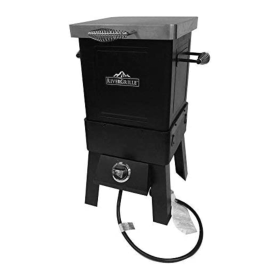
Oil-less Fryer & Roaster
Model number: TF2201802-RG
Pacific Standard Time
(Made in China)
Page 1 of 30
(Tank Not Included)
20160927-Ver.1
Advertisement
Table of Contents

Related Manuals for RiverGrille TF2201802-RG


Summary of Contents for RiverGrille TF2201802-RG
- Page 1 Oil-less Fryer & Roaster Model number: TF2201802-RG ASSEMBLY & OPERATING INSTRUCTIONS Tools required (not included): Phillips screwdriver / Adjustable wrench For Outdoor Use Only (Tank Not Included) To installer or person assembling this appliance: Leave this manual with this appliance for future reference.
-
Page 2: Safety Symbols
SAFETY SYMBOLS: The symbols and boxes shown below explain what each heading means. Read and follow all of the messages found throughout the manual. DANGER: Indicates an imminent hazardous situation which if not avoided will result in death or serious injury. WARNING: Indicates a potentially hazardous situation which, if not avoided, could result in death or serious injury. -
Page 3: Prop 65 Warning
DANGER (a) Do not store a spare LP gas cylinder under or near this appliance; (b) Never fill the cylinder beyond 80 percent full; (c) If the information in (a) and (b) is not followed exactly, a fire causing death or serious injury may occur. - Page 4 Leak tests must be conducted prior to each use. Appliance is hot when in use. To avoid burns: DO NOT attempt to move the appliance. Wear protective gloves or oven mitts. DO NOT touch any hot surfaces. ...
- Page 5 WARNING Never move the appliance when in use. Never operate appliance with LP cylinder out of correct position specified in assembly instructions. Always close LP cylinder valve and remove coupling nut before moving LP cylinder from specified operating position. ...
-
Page 6: Before Installing
USE AND INSTALLATION OF LP GAS CYLINDER (PROPANE TANK) BEFORE INSTALLING: The installation must conform with local codes or, in the absence of local codes, with either the National Fuel Gas Code, ANSI Z223.1/NFPA 54, Natural Gas and Propane Installation Code, CSA B149.1, or Propane Storage and Handling Code, B149.2, or the Standard for Recreational Vehicles, ANSI A 119.2/NFPA 1192, and CSA Z240 RV Series, Recreational Vehicle Code, as applicable. - Page 7 DANGER DO NOT connect this appliance to an existing #510 POL cylinder valve with Left hand threads. The Type 1 valve can be identified with the large external threads on the valve outlet. DO NOT connect to a propane cylinder exceeding its capacity. ...
-
Page 8: Connection Procedures
CONNECTION PROCEDURES Make sure the cylinder valve is closed (turn Cylinder Valve/Knob valve clockwise until tight). Check the cylinder valve to insure it has the proper external male threads. Make sure all burner valves are turned OFF. Inspect valve connections, port, and regulator assembly. -
Page 9: Product Diagram
PRODUCT DIAGRAM Page 9 of 30 20160927-Ver.1... -
Page 10: Component List
COMPONENT LIST 1. Lid Assembly 2. Body Assembly 3. Match Hole Cover Qty: 1pc Qty: 1pc Qty: 4pcs 4. Lid Handle, Silver 5. Rear Leg 6. Basket Qty: 1pc Qty: 2pcs Qty: 1pc 7. Grease Tray 8. Front Left Leg 9. - Page 11 13. Meat Thermometer 14. Lifting Hook 15. Fryer Handle, Black Qty: 1pc Qty: 1pc Qty: 2pcs REPLACEMENT PART LIST (I) Page 11 of 30 20160927-Ver.1...
-
Page 12: Hardware List
REPLACEMENT PART LIST (II) Part Part Name Part Part Name Number Number Lid Assembly Upper Hinge Body Assembly Lower Hinge Main Body Heat Shield Burner Ignition Electrode & Wire Fire Box Match Hole Cover Lid Handle, Silver Rear Leg Basket Grease Tray Front Left Leg Front Right Leg... -
Page 13: Assembly Procedures
ASSEMBLY PROCEDURES Step 1 Attach the Rear Leg (5), Front Left Leg (8) and Front Right Leg (9) to the Body Assembly (2) by using 12 pcs M6x8mm Bolt (A). Step 2 Attach the Control Panel And Regulator Assembly (10) to the front legs by using 4 pcs M6x8mm Bolt (A) as shown. - Page 14 Step 3 Attach the Orifice Bracket to the bottom of body assembly by using 2 pcs M6x8mm Bolt (A) as shown. Make sure that the valve outlet (orifice) is inserted STRAIGHTLY into the burner port. Correct Position Incorrect Position Step 4 Insert the terminal of ignition wire into the connector of burner valve.
- Page 15 Step 5 Attach the Match Hole Covers (3) to the body assembly by using 4 pcs M6 Step Bolt (B). Make sure that the covers can swing smoothly. Step 6 Attach the Fryer Handle, Black (15) to the body assembly by using 4 pcs M6x8mm Bolt (A).
- Page 16 Step 7 Attach the Lid Assembly (1) to the body assembly by using 2 pcs Hinge Pin (C) and 2 pcs Cotter Pin (D). Step 8 Attach the Lid Handle, Silver (4) to the lid by using 2 pcs M6x8mm Bolt (A) and 4 pcs Heat Insulation Washer (E).
- Page 17 Step 9 Insert the Grease Tray (7) into the sliding slots at the bottom of the body assembly as shown. Suggest using a disposable aluminum tray as a liner. Tip: Grease tray sized to hold a disposable aluminum tray. Step 10 Position the Grease Collector (12) into the fryer body and make sure that it is fixed by 4 guiding pins in the fryer body as shown Page 17 of 30...
- Page 18 Step 11 Place the Flame Tamer (11) into the guiding pins on the grease collector as shown. Step 12 Place the Basket (6) into the fryer body (on the grease collector) as shown. Page 18 of 30 20160927-Ver.1...
- Page 19 Step 13 Your unit is fully assembled! Make sure to read and follow the Instruction Manual before using this appliance. When transporting or storing the appliance without tank attached, hook the regulator onto the handle to prevent damage to regulator. Page 19 of 30 20160927-Ver.1...
-
Page 20: Before Testing
LEAK TEST GENERAL Although all gas connections on the appliance are leak tested at the factory prior to shipment, a complete gas tightness check must be performed at the installation site due to possible mishandling in shipment, or excessive pressure unknowingly being applied to the unit. Periodically check the entire system for leaks following the procedures listed below. -
Page 21: Lighting Instructions
3. If a leak is present, immediately turn off the gas supply and tighten the leaky fittings. 4. Turn the gas back on and recheck. 5. Should gas continue to leak from any of the fittings, turn off the gas supply and contact customer service department at (888) 837-1380, 8 a.m. -
Page 22: Match-Lighting
If ignition does NOT occur in 5 seconds, turn the control knob off, wait 5 minutes to allow gas to dissipate. Repeat the lighting procedure. To turn burner off, turn the control knob clockwise until it locks in the OFF position. MATCH-LIGHTING Open the lid and make sure control knob is in OFF position. -
Page 23: Flame Characteristics
DANGER Do not lean over appliance while lighting. FLAME CHARACTERISTICS This procedure outlines how to check for proper burner flame characteristics. Burner flames should be blue and stable with little yellow tips, with no excessive noise, or lifting. If the flame is yellow, it indicates insufficient air. -
Page 24: Maintenance And Cleaning Instructions
MAINTENANCE & CLEANING INSTRUCTIONS CAUTION Keep outdoor cooking gas appliance area clear and free from combustible materials, gasoline and other flammable vapors and liquids. Keep the ventilation openings of the cylinder enclosure free and clear of debris. Check and clean burner for insects and insect nests. A clogged burner can lead to a fire beneath the appliance. - Page 25 Although an obstructed burner tube is not the only cause of flashback, it is the most common cause. To reduce the chance of flashback, you must clean the burner tube before assembling your appliance, and at least once a month in late summer or early fall when spiders are most active.
-
Page 26: Burner Cleaning
BURNER CLEANING: Clean the exterior of the burner with a brass brush. Use a metal scraper to remove stubborn stains. Clear clogged ports with a straightened paper clip. Never use a wooden toothpick as it may break off and clog the port. If insects or other obstructions are blocking the flow of gas through the burner, call customer service at (888) 837-1380. -
Page 27: Food Safety
FOOD SAFETY Food safety is very important for enjoying your outdoor cooking experience. To keep food safe from harmful bacteria, follow below basic steps: Clean: Wash hands, utensils, and surfaces with hot soapy water before and after handling raw meat and poultry. Separate: Separate raw meats and poultry from ready-to-eat foods to avoid cross contamination. -
Page 28: Troubleshooting
TROUBLE SHOOTING Problem: Possible Causes: Corrective Actions: Burner will not 1. LP cylinder fuel is used 1. Change a new full LP cylinder. light 2. Check to see if the burner will light using 2. Bad electrode spark. a match. Electrode may need to adjust. 3. -
Page 29: Limited Warranty
LIMITED WARRANTY Manufacturer warrants this Product to be free from defects in workmanship and materials for a period of Ninety (90) days from the date of purchase, PROVIDED claims are submitted, in writing, with proof of purchase. If any part of this item fails because of a manufacturing defect within the Limited Warranty Period, Manufacturer offers to replace such part(s) provide that such parts have not been improperly repaired, altered, or tampered with or subject to misuse, abuse or exposed to corrosive conditions. - Page 30 Optional Accessories Available Please visit www.homedepot.com for more information Model # BA2258301-RG Model # BA2258401-RG Roasting Rack Rib Rack Model # AC2257201-RG Oil-less Fryer & Roaster Cover Should you encounter any problem Obtaining replacement parts CALL US FIRST. Do not return product to the store. WE CAN HELP.
Need help?
Do you have a question about the TF2201802-RG and is the answer not in the manual?
Questions and answers