Table of Contents
Advertisement
Quick Links
www.orionbms.com
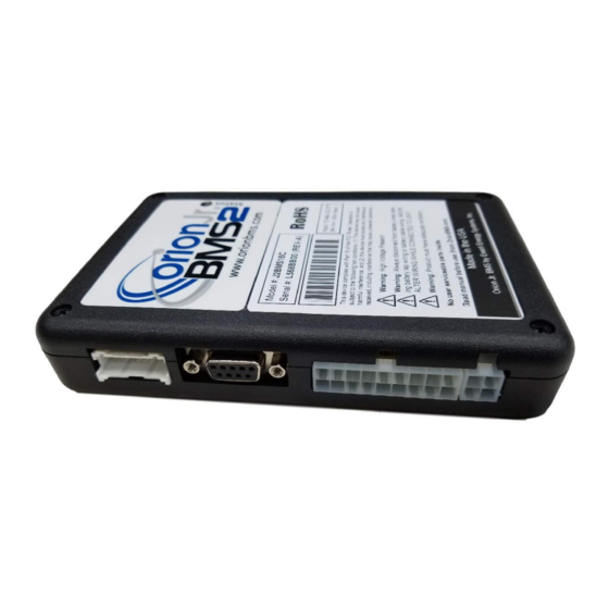
Orion Jr. 2 BMS Operation Manual
The Orion Jr. 2 BMS by Ewert Energy Systems is designed to manage and protect lithium ion
battery packs up to 48v nominal (maximum voltage never to exceed 60V at any time). The Orion Jr. 2
BMS is built on the same technology as the standard Orion BMS product line, but it is smaller and
lighter and is specifically designed with features for stationary and light mobile applications such as
solar & wind storage, UPS systems, golf carts, forklifts, scooters and more.
Advertisement
Table of Contents

Related Manuals for Ewert Energy Systems Orion Jr. 2 BMS

Summary of Contents for Ewert Energy Systems Orion Jr. 2 BMS
- Page 1 Orion Jr. 2 BMS Operation Manual The Orion Jr. 2 BMS by Ewert Energy Systems is designed to manage and protect lithium ion battery packs up to 48v nominal (maximum voltage never to exceed 60V at any time). The Orion Jr. 2...
-
Page 2: Table Of Contents
Setting up the BMS ..........................4 Wiring ....................................4 Software ..................................4 Testing ..................................... 4 How the Orion Jr. 2 BMS Works ......................5 Changing and Uploading Settings ........................... 5 Basic Data Collection ..............................5 CHARGE and READY Modes ............................7 Charge and Discharge Current Limits .......................... -
Page 3: Overview Of Theory Of Operation
The Orion Jr. 2 BMS unit monitors the voltage of each individual cell (through the cell tap wires) to en- sure cell voltages remain within a specified range. Using the collected information, which includes pa- rameters such as minimum and maximum cell voltages, temperature, and state of charge, the BMS calculates amperage limits for both charge and discharge. -
Page 4: Setting Up The Bms
Orion Jr. 2 BMS Operation Manual Setting up the BMS Wiring Please see the wiring manual for information regarding wiring the BMS into the application. The wiring manual can be downloaded from www.orionbms.com/downloads. Software Please see the software manual for information on setting up specific software parameters and battery profile information. -
Page 5: How The Orion Jr. 2 Bms Works
Changing and Uploading Settings The Orion Jr. 2 BMS must be programmed in order to operate. A complete set of settings is called a pro-file. Settings are edited on a personal computer using the Orion Jr. 2 BMS Utility software and then are “uploaded”... - Page 6 This figure demonstrates the relationship between the voltage output and current measured on the current sensor The currents sensors sold with the Orion Jr. 2 BMS are available in sizes up to 1000A. The BMS can be configured to use 2 parallel current sensors to measure amperages up to 2000A, however the max- imum recommended size is 1000A.
-
Page 7: Charge And Ready Modes
While some motor controllers or chargers don’t support CANBUS, they may support an analog voltage input that represents the current limit. The Orion Jr. 2 BMS has 0 to 5 volt analog outputs which repre- Document Revision: 1.0... -
Page 8: How The Bms Calculates Current Limits
Orion Jr. 2 BMS Operation Manual sent the maximum current limits in an analog voltage. This operates the same way as the CANBUS support, but is less accurate and less desirable than CANBUS control. If the 0 to 5 volt analog outputs... - Page 9 Orion Jr. 2 BMS Operation Manual the discharge current limit, a state of charge is specified where to begin reducing the discharge current limit along with a value of amps per percentage state of charge. For most applications, this feature is not used and should be disabled to prevent errant SOC calculations from altering the usable range of the pack unless there is a specific reason for enabling it.
-
Page 10: Selecting Current Limit Settings
Selecting Current Limit Settings The Orion Jr. 2 BMS utility has data for many common cell types already pre-loaded into the utility. These can be accessed by using the Profile Setup Wizard in the BMS utility. For cells which are not listed, or if custom settings are required, the following guidelines may be helpful for selecting proper values. -
Page 11: State Of Charge Calculation
Note: The Orion Jr. 2 BMS cannot calculate state of charge without a current sensor! The Orion Jr. 2 BMS calculates a battery pack’s state of charge (SOC) primarily by coulomb counting, or by keeping track of how much current has entered or left the battery pack. This method requires the use of a current sensor and generally tracks the state of charge of the battery pack quite well provided that the capacity of the battery is known and the current sensor is accurate. -
Page 12: Why Soc Correction Drifts Happen
Orion Jr. 2 BMS Operation Manual In addition to the drift points that are programmed in, the BMS also knows what state of charge the bat- tery is at when a charge cycle completes. Since the BMS is controlling the battery charger, the BMS will set the state of charge to the “Charged SOC”... -
Page 13: Determining State Of Charge Correction Drift Points
7. Inaccurate open circuit voltage calculations due to an incorrectly installed or defective current sensor. Note: The Orion Jr. 2 BMS cannot calculate state of charge without a current sensor! If a current sensor is not connected, the Orion Jr. 2 BMS will derive the state of charge based strictly on instantaneous cell voltages. - Page 14 Orion Jr. 2 BMS Operation Manual This service will produce default settings for cell resistance measured at different temperatures, SOC settings, and standard voltage settings. This service requires at least one sample cell and the manufac- turer datasheet. For common cells which are not in the database yet, the service may be discounted or free when a sample is provided.
-
Page 15: State Of Health Calculation
The state of charge drift points in the Orion Jr. 2 BMS are not jump points. This means that when the open cell voltage on a particular cell reaches a drift point, it will not immediately jump to the provided state of charge. -
Page 16: How The Bms Calculates Internal Resistance
How the BMS Calculates Internal Resistance The Orion Jr. 2 BMS depends on external changes in current to be able to back calculate the re- sistance of each individual cell Therefore, the BMS does not initially know the cell resistances and will begin by using pre-programmed default resistances based on the temperature of the cells. -
Page 17: Determining Nominal Resistance
The Orion Jr. 2 BMS allows the user to specify the nominal resistance for each temperature range in increments of 5 degrees Celsius. This allows for using any type of different Lithium ion battery regard- less of how unique its resistance curve is. -
Page 18: Controlling Loads And Chargers
Controlling Loads and Chargers The Orion Jr. 2 BMS makes decisions about whether or not the battery pack can accept charge or dis- charge. As the BMS does not have integrated switches or contactors, the BMS unit cannot stop current flowing in or out of the battery pack by itself. - Page 19 Orion Jr. 2 BMS Operation Manual BMS must allow charge to re-occur once the battery pack has been discharged a certain amount, such as in solar, wind, and some standby power applications. Criteria for all 3 relay outputs All 3 of the relay outputs will turn off if their respective current limit reaches zero amps (charge enable and charger safety both use the charge current limit, while discharge enable uses the discharge current limit).
- Page 20 Orion Jr. 2 BMS Operation Manual conditions are met, though usually only one condition is used. Care must be taken to prevent oscillations, so values must be chosen far enough apart as not to allow the output to turn on again immediately.
- Page 21 Orion Jr. 2 BMS Operation Manual Charge Enable Flow Chart Document Revision: 1.0 Last Updated: 8/30/2018...
- Page 22 Orion Jr. 2 BMS Operation Manual Discharge Enable Flow Chart Document Revision: 1.0 Last Updated: 8/30/2018...
- Page 23 While the BMS can turn on the charger again to continue balancing if it is allowed to do so in the set- tings, the Orion Jr. 2 BMS switches off the charger completely when a cell reaches the maximum volt- age and will continue to balance the pack after the charger has turned off.
- Page 24 Orion Jr. 2 BMS Operation Manual Charger safety flow chart Document Revision: 1.0 Last Updated: 8/30/2018...
-
Page 25: Watchdog Circuit
Orion Jr. 2 BMS Operation Manual Watchdog Circuit The four primary relay outputs on the BMS (Charge Enable, Discharge Enable, Charger Safety and Multi-Purpose Enable) are protected by a secondary monitoring circuit (called the watchdog). Specifi- cally, the watchdog provides redundant monitoring of critical data (cell voltages and temperatures) to confirm that the main processor is interpreting data correctly. -
Page 26: How Balancing Works
BMS has been integrated with the application properly. The Orion Jr. 2 BMS uses passive balancing to remove charge from the highest cells in order to main- tain the balance of the pack. The passive shunt resistors dissipate up to approximately 150mA per cell. - Page 27 The Orion Jr. 2 BMS is not designed to do an initial balance on a battery pack that is more than about 10-15 amp hours out of balance. In those cases, the battery pack should be pre-balanced by either charging the cells to roughly the same SOC one by one or by charging / discharging the lowest and highest cells so that they are roughly at the same SOC.
- Page 28 Orion Jr. 2 BMS Operation Manual over-discharge and to prevent a possible race condition where the BMS removes charge from alternat- ing cells. Balancing will be disabled completely if the BMS enters into a voltage failsafe mode such as if an open cell tap wire is detected.
-
Page 29: Open Wire Fault Detection Circuit
The Orion Jr. 2 BMS can be configured to turn the charger back on at set intervals if necessary to con- tinue the balancing process. This is configured in the settings for the charger safety relay settings. For certain chemistries it may be desirable to turn the charger back on every 30 minutes to an hour to aid in the balancing process. -
Page 30: Busbar Compensation
Busbar Compensation Voltage measurements are taken by the Orion Jr. 2 BMS with respect to the next lowest cell or the negative wire in each cell group. For example, when the Orion Jr. 2 BMS measures cell 1’s voltage, it measures the voltage between tap 1- and 1. - Page 31 (between cell 8 and 9) such that voltage drop in- duced by the busbar cannot be seen by the Orion Jr. 2 BMS. Whenever possible, it is best to wire the cell taps such that the BMS cannot see the extra resistance.
-
Page 32: Thermal Management And Fan Controller
Orion Jr. 2 BMS Operation Manual Voltage drop under load from an uncompensated high impedance busbar causing additional voltage drop (blue line) The BMS allows busbar compensation to be added to specific cells in the cell population table. The compensation must be applied to the cell where the extra resistance shows up. This depends on the physical placement of the cell tap wires as the tap could be placed before or after the long cable. -
Page 33: Multi-Purpose Input
Orion Jr. 2 BMS Operation Manual The Orion Jr. 2 BMS measures the battery temperature through 3 main thermistors connected directly to the BMS with the option of additional thermistors through a thermistor expansion module (sold sepa- rately). The BMS calculates the minimum, maximum, and average temperatures of the battery pack based on the attached thermistors. -
Page 34: Multi-Purpose Output
Orion Jr. 2 BMS Operation Manual the Charge Power input being energized (Main I/O harness pin 4) however in some situations this may not be possible and so this input function allows for an alternate method to do so. Multi-Purpose Output The BMS has one multi-purpose output. -
Page 35: Collected Statistics (Cell Warranty Data)
Orion Jr. 2 BMS Operation Manual hysteresis threshold. Note: This output is not designed to be the primary control for discharge or charge. NOTE: This output is not designed to be the primary control for discharge or charge. Use the charge enable, discharge enable, charger safety or CANBUS for primary con- trol of charge and discharge. - Page 36 The data is collected only while the Orion Jr. 2 BMS is powered up. The Orion Jr. 2 BMS also maintains an event log. Events include outputs turning on and off, state of charge drifts, charge completion, and other related events. This log is intended to be used to aide in diagnosing intermittent issues or events that happen only at certain points in time.
-
Page 37: Failure Mitigation
Orion Jr. 2 BMS Operation Manual Failure Mitigation The Orion Jr. 2 BMS features several failsafe modes to protect the battery pack should something go wrong with the BMS unit or attached wiring. Although these internal redundancies and protection pro- cedures are provided, it is the responsibility of the user to ensure that the BMS is configured, connect- ed, and used in a manner in which failures are properly mitigated and handled. - Page 38 BMS’s data collection system. 4. Loose / disconnected wire or failure of current sensor system – The Orion Jr. 2 BMS will enter into a current sensor fault if the actual current measured is greater than +/- 120% of the maximum rating of the current sensor.
- Page 39 Orion Jr. 2 BMS Operation Manual less than -40C or greater than +80C (a shorted or disconnected thermistor will read +81C or - 41C.) In the event that a thermistor fault occurs, the BMS will disregard that particular thermistor. A thermistor failure (such as the use of an incorrect type of thermistor) may result in an inaccurate temperature reading, which may result in current limits being imposed on the battery pack incorrectly.
- Page 40 BMS is unable to force a relay to turn off if it has failed. After the Orion Jr. 2 BMS attempts to turn off one of the relays (charge enable, discharge enable, or charge safety), it will continue to monitor to ensure that current flow has stopped.
-
Page 41: Understanding Failure Modes
Orion Jr. 2 BMS Operation Manual Understanding Failure Modes The Orion Jr. 2 BMS has several failsafe software modes to ensure that the batteries are protected against internal and some external failures of the BMS. These modes are designed to place the priority on protecting the battery. -
Page 42: Diagnostic Trouble Codes
Orion Jr. 2 BMS Operation Manual 3. Internal memory failsafe (non-operating mode) - In the event of an internal BMS memory failure (i.e. if the memory that stores the profile is damaged), the BMS will load the factory default battery profile with all outputs and inputs disabled to protect the battery. A diagnostic trouble code will be set to indicate this problem has occurred.
Need help?
Do you have a question about the Orion Jr. 2 BMS and is the answer not in the manual?
Questions and answers