
Related Manuals for Toro CT2240


Summary of Contents for Toro CT2240
-
Page 1: Figure
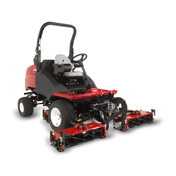
Form No. 3410-785 Rev A CT2240 Compact Triple 4-Wheel Drive Turf Mower Model No. 30654—Serial No. 400000000 and Up G025163 *3410-785* A Register at www.Toro.com. Original Instructions (EN) -
Page 2: Table Of Contents
Starting and Shutting Off the Engine......24 Adjusting the Center Cutting Unit Height-of-Cut You may contact Toro directly for product and accessory Correction ............26 information, help finding a dealer, or to register your product. Controlling the Position of the Individual Cutting Whenever you need service, genuine Toro parts, or additional Units..............26... -
Page 3: Safety
Safety Removing Debris from the Cooling System ....41 Brake Maintenance ............42 Towing the Machine ..........42 This machine has been designed in accordance with EN ISO Belt Maintenance ............44 5395:2013. Tensioning the Alternator Belt .........44 Controls System Maintenance ........44 General Safety Checking the Forward/Reverse Travel Pedal Action...............44 Using this product for purposes other than its intended use... - Page 4 • – control of a ride-on machine sliding on a slope will Never operate the machine with damaged guards, shields, not be regained by the application of the brake. The or without safety protective devices in place. Be sure all main reasons for loss of control are: interlocks are attached, adjusted properly, and functioning properly.
- Page 5 • • Use care when loading or unloading the machine into a Lower a folding roll bar temporarily only when necessary. trailer or truck. Do not wear the seat belt when the roll bar is folded down. • Use care when approaching blind corners, shrubs, trees, or other objects that may obscure vision.
-
Page 6: Toro Riding Mower Safety
Toro Riding Mower Safety • Keep all nuts, bolts and screws tight to be sure the The following list contains safety information specific to Toro equipment is in safe working condition. products or other safety information that you must know that is not included in the safety standards. - Page 7 Authorized Toro Distributor. • To ensure optimum performance and continued safety certification of the machine, use only genuine Toro replacement parts and accessories. Replacement parts and accessories made by other manufacturers could be dangerous, and such use could void the product warranty.
-
Page 8: Safety And Instructional Decals
Safety and Instructional Decals Safety decals and instructions are easily visible to the operator and are located near any area of potential danger. Replace any decal that is damaged or missing. decal70-13-072 decal111-0773 70-13-072 111-0773 1. Jacking point 1. Warning—crushing of fingers, force applied from side. decal70-13-077 70-13-077 1. - Page 9 decal111-3567 111-3567 decal111-3344 111-3344 1. Pedal operation to control machine direction 1. Ignition switch indicating different positions of key switch decal111-3902 111-3902 1. Warning—cutting hazard of hand, fan. 2. Hot surfaces—read the Operator's Manual for more information. decal111-3562 111-3562 1. Press pedal to adjust steering wheel tilt. decal111-3901 111-3901 1.
- Page 10 decal111-8098 111-8098 1. Tipping hazard—drive slowly when turning or going up slopes. 3. Tipping hazard—wear a seatbelt when the ROPS is up; do not wear a seatbelt when the ROPS is down. 2. TIpping hazard—only drive up slopes that are between 0 and 4.
- Page 11 decal111-7249 111-7249 1. Daily service interval 6. Check hydraulic fluid level 11. Check cutting unit setting 16. Lubrication points for daily interval 2. 50 hour service interval 7. Check fuel level 12. Check engine coolant level 17. Lubrication points for 50 hour interval 3.
-
Page 12: Setup
Setup Media and Additional Parts Description Qty. Operator's Manual Read the manuals before operating the machine. Engine operator’s manual Product Overview Store all documentation in a safe place for future use. Note: Determine the left and right sides of the machine from the normal operating position. -
Page 13: Controls
Controls Control Panel Components 13 16 14 17 8 g014419 g014419 Figure 4 1. Weight transfer control G014418 g014418 Figure 3 1. Parking brake switch 11. Horn button 2. Limited lift in reverse 12. Auxiliary 12 volt socket switch (supplied with a 12 V kit) 3. - Page 14 WARNING The parking brake operates on the front wheels only. Do not park the mower on a slope. G014547 G014421 g014547 g014421 Figure 7 Figure 6 1. Throttle control lever 1. Parking brake Traction Pedals Emergency Brake Forward travel: Press the forward travel pedal to increase In the event of service brake failure, turn the ignition off to forward travel speed.
- Page 15 Transport Latches Always raise the cutting units to the transport position and secure with the transport latches and safety locks when travelling between work areas (Figure G014549 g014549 Figure 10 Operator Seat WARNING Never operate the mower without first checking that the operator seat mechanisms are in good working order and that, once adjusted and locked, the seat remains securely in position.
- Page 16 G014551 g014551 Figure 12 1. Engine coolant overheating warning light Hydraulic Fluid Overheating Warning Light The hydraulic fluid warning light illuminates when overheating occurs and the horn is actuated when the hydraulic fluid in the reservoir exceeds 95 degrees C (203 degrees F); refer to Figure G014550 g014550...
- Page 17 Ignition Key Low Battery Charge Warning Light The battery charge warning light illuminates when low battery 0 = Engine off charge occurs (Figure 14). I = Engine run/Auxiliary on II = Engine pre-heat III = Engine start CAUTION If you leave the key in the ignition switch, someone G014553 could accidently start the engine and seriously g014553...
- Page 18 Fuel Gauge Cutting Unit Drive Switch Indicator Light The fuel gauge shows the amount of fuel in the tank (Figure 19). This light illuminates when the cutting unit drive switch is in the F position and the ignition key is ORWARD EVERSE turned to position I...
-
Page 19: Specifications
32 L (8.5 US gallons) Attachments/Accessories A selection of Toro approved attachments and accessories is available for use with the machine to enhance and expand its capabilities. Contact your Authorized Service Dealer or Distributor. To best protect your investment and maintain optimal performance of your Toro equipment, count on Toro genuine parts. -
Page 20: Checking The Cooling System
sump for at least 10 minutes before checking. If the oil level is at or below the Add mark on the dipstick, add oil to bring the oil level to the Full mark. Do not overfill the crankcase. If the oil level is between the Full and Add marks, no oil addition is required. -
Page 21: Adding Fuel
WARNING Fuel is harmful or fatal if swallowed. Long-term exposure to vapors can cause serious injury and illness. • Avoid prolonged breathing of vapors. • Keep your face away from the nozzle and fuel tank or conditioner opening. • Keep fuel away from your eyes and skin. DANGER In certain conditions, fuel is extremely flammable and highly explosive. -
Page 22: Checking The Hydraulic Fluid
Note: The level needs to be at the upper mark. Alternative fluids: If the Toro fluid is not available, other conventional, petroleum-based fluids may be used, provided 3. If additional hydraulic fluid is needed, clean the area... -
Page 23: Checking The Tire Pressure
4. Remove the cap and fill the tank to the upper mark DANGER on the sight level gauge. Operating on wet grass or steep slopes can cause Note: Do not overfill the tank. sliding and loss of control. 5. Install the cap onto the tank. Wheels dropping over edges can cause rollovers, which may result in serious injury, death, or Checking the Tire Pressure... -
Page 24: Understanding The Operator Presence Controls
Understanding the Operator WARNING Presence Controls Operating the machine when the operator platform latching mechanism is not fully engaged or is Note: The engine shuts off if you leave the seat without malfunctioning could lead to serious injury. engaging the parking brake. Never operate the machine without first checking Engine Start Lockout:You can start the engine only when that the operator platform latching mechanism is... - Page 25 Starting a Warm Engine WARNING 1. Sit on the seat, keep your foot off the traction pedal so Operating the machine in an unsafe manner could that it is in Neutral, engage the parking brake, and set result in personal injury. the throttle to the 70 percent full throttle.
-
Page 26: Adjusting The Center Cutting Unit Height-Of-Cut Correction
Adjusting the Center Cutting Unit Height-of-Cut Correction With all cutting units set at the same HOC via the indicator rings, you may notice that the center unit produces a higher cut finish compared to the wing units. The center unit is pulled and the wing units are pushed;... -
Page 27: Clearing The Cutting Units
Using Weight The cutting unit drive can be engaged only when the operator is seated correctly, refer to Checking the Operator Presence Transfer/Traction Assistance Seat Switch (page 44). A variable hydraulic weight transfer system is provided for Forward rotation cutting unit drive engagement: Press improving tire grip with the grass surface—traction assistance. -
Page 28: Locating The Jacking Points
2. Support the weight of the upper frame while removing WARNING the R-clips and pins from the pivot brackets (Figure 34). When lowering and raising the ROPS frame, fingers 3. Carefully lower the frame downwards until it rests on may get pinched between the machine and the the stops. -
Page 29: Transporting Machines
Operating Tips Becoming Familiar with the Machine Before mowing grass, practice operating the machine in an open area. Start and shut off the engine. Operate in forward and reverse. Lower and raise the cutting units and engage and disengage the cutting units. When you feel familiar with the machine, practice operating up and down slopes at different speeds. - Page 30 Important: Take care when travelling over obstacles such as roadside curbs. Always travel at slow speed over obstacles to prevent damage to the tires, wheels, and the steering system. Ensure that the tires are inflated to the recommended pressure. Using the Rear Roller Scrapers Remove the rear roller scrapers where conditions allow, as optimum grass discharge is achieved without them.
-
Page 31: Maintenance
Maintenance Note: Determine the left and right sides of the machine from the normal operating position. Note: To obtain an electrical schematic or a hydraulic schematic for your machine, visit www.Toro.com. Recommended Maintenance Schedule(s) Maintenance Service Maintenance Procedure Interval • Check the condition and tension of the alternator belt. -
Page 32: Daily Maintenance Checklist
Maintenance Service Maintenance Procedure Interval • Drain and clean the fuel tank Before storage • Flush and replace the cooling system fluid. • Replace all moving hoses. Every 2 years • Replace the transmission cable. Daily Maintenance Checklist Duplicate this page for routine use. For the week of: Maintenance Check Item Mon. -
Page 33: Preparing The Machine For Maintenance
Important: Regular maintenance is essential for the continued safe operation of the machine. Correct servicing will prolong the working life of the machine and safeguard the Warranty. Always use genuine Toro service parts as these are accurately matched to the required duty. -
Page 34: Lubrication
Lubrication immediately after every washing, regardless of the interval listed. Replace any damaged grease fittings. Greasing the Bearings, Grease all cutting unit grease points and ensure that sufficient Bushings, and Pivots grease is injected such that clean grease is seen to escape from the roller end caps. -
Page 35: Engine Maintenance
Engine Maintenance Checking the Engine Overheat Warning System Service Interval: Every 500 hours G014565 g014565 Figure 39 2. Before removing the filter, use low-pressure air (40 psi, clean and dry) to help remove large accumulations of debris packed between outside of the filter and the canister. -
Page 36: Servicing The Engine Oil And Filter
Servicing the Safety Filter The air filter has a secondary, safety filter element inside the primary air filter to prevent dislodged dust and other items from entering the engine while changing the main element. Replace the safety filter, never clean it. Important: Never attempt to clean the safety filter. -
Page 37: Fuel System Maintenance
Fuel System DANGER Maintenance Under certain conditions, diesel fuel and fuel vapors are highly flammable and explosive. A fire or explosion from fuel can burn you and others and DANGER can cause property damage. Under certain conditions, diesel fuel and fuel •... -
Page 38: Electrical System Maintenance
Electrical System Maintenance Important: Before welding on the machine, disconnect both cables from the battery, both wire harness plugs from the electronic control module, and the terminal connector from the alternator to prevent damage to the electrical system. Checking the Electrical System Service Interval: Every 500 hours Inspect all electrical connections and cables and replace any... -
Page 39: Servicing The Battery
Servicing the Battery Drive System Maintenance Service Interval: Every 250 hours DANGER Changing the Transmission Battery electrolyte contains sulfuric acid which is Oil Filter fatal if consumed and causes severe burns. • Do not drink electrolyte and avoid contact with Service Interval: After the first 50 hours skin, eyes, or clothing. -
Page 40: Checking The Rear Wheel Alignment
To adjust the alignment of the rear wheels, first back off the left and right locknuts on the track rod assembly. (The left locknut has left-hand threads). Rotate the track rod to achieve the correct distance as described above and tighten the locknuts securely. -
Page 41: Cooling System Maintenance
Cooling System Maintenance Removing Debris from the Cooling System Service Interval: Before each use or daily Every 100 hours Every 2 years Note: To prevent the engine from overheating, the radiator and oil cooler must be kept clean. Normally, check them daily and, if necessary, clean any debris off these parts. -
Page 42: Brake Maintenance
Brake Maintenance Towing the Machine Ensure that the towing vehicle specification is suited to braking the combined vehicle weight and able to remain in complete control at all times. Ensure that the parking brake of the towing vehicle is applied. Chock the mower front wheels to prevent the mower from rolling away. - Page 43 g014451 g014451 Figure 54 1. Front wheel moto 3. Washer M12 2. Hex plug 4. Setscrew M12 x 40 mm D. Identify the left front wheel motor disc brake G014450 g014450 assembly and repeat the previous procedure. Figure 53 E. Remove the wheel chocks. 1.
-
Page 44: Belt Maintenance
Belt Maintenance Controls System Maintenance Check the condition and tension of the alternator belt after the first day of operation and every 100 operating hours thereafter. Checking the Forward/Reverse Travel Pedal Action Tensioning the Alternator Belt With the engine shut off, operate the forward and reverse Service Interval: After the first 8 hours travel pedals through the full range of articulation and ensure Every 100 hours... -
Page 45: Checking The Transmission Neutral Interlock Switch
Checking the Transmission Hydraulic System Neutral Interlock Switch Maintenance 1. Shut off the engine. WARNING 2. Remove your foot from the forward/reverse travel pedals. Hydraulic fluid escaping under pressure can penetrate skin and cause injury. 3. Turn the ignition key to position I and the transmission neutral indicator light should illuminate. -
Page 46: Checking The Hydraulic Fluid Overheat Warning System
Checking the Hydraulic Lines and Hoses Daily, check hydraulic lines and hoses for leaks, kinked lines, loose mounting supports, wear, loose fittings, weather deterioration, and chemical deterioration. Make all necessary repairs before operating. G014452 g014452 Figure 56 3. Filler strainer 1. -
Page 47: Cutting Units System Maintenance
Cutting Units System 80-grade carborundum paste Part No. Maintenance 0.45 kg (1 lb) 63-07-088 11.3 kg (25 lb) 63-07-086 Back Lapping the Cutting Units WARNING Contact with the cutting units or other moving parts can result in personal injury. • Keep your fingers, hands, and clothing away from the cutting units or other moving parts. -
Page 48: Grinding The Cutting Units
Grinding the Cutting Units Do not dispose of batteries with a separate collection mark into general waste. You will need to grind the reel edges or bedknife edges that When disposing of hazardous waste products, take them have become excessively rounded or distorted. Bedknives that to an authorized disposal site. -
Page 49: Storage
B. Clean the battery, terminals, and posts with a wire brush and baking soda solution. C. Coat the cable terminals and battery posts with Grafo 112X skin-over grease (Toro Part No. 505-47) or petroleum jelly to prevent corrosion. D. Slowly recharge the battery every 60 days for 24 hours to prevent lead sulfation of the battery. -
Page 50: Troubleshooting
Troubleshooting Problem Possible Cause Corrective Action There are areas of uncut grass at the 1. You are turning too tightly. 1. Increase the turning radius overlap between cutting units. 2. The machine slides sideways when 2. Mow up/down the slope. travelling across the face of a slope. - Page 51 Problem Possible Cause Corrective Action There is scalping of the turf. 1. The undulations are too severe for the 1. Use floating cutting units. height of cut setting. 2. The height of cut is too low. 2. Raise the height of cut. There is excessive bedknife wear.
- Page 52 Problem Possible Cause Corrective Action There is no machine movement in forward 1. The parking brake is engaged. 1. Disengage the parking brake. or reverse. 2. The fluid level is low. 2. Fill the reservoir to the correct level. 3. The reservoir has the wrong kind of 3.
- Page 53 Problem Possible Cause Corrective Action A cutting unit fails to lift out of work. 1. There is a lift cylinder seal failure. 1. Replace the seals. 2. The pressure relief valve is jammed 2. Have the relief valve pressure checked. open or wrongly set.
- Page 54 Notes:...
- Page 55 The Way Toro Uses Information Toro may use your personal information to process warranty claims, to contact you in the event of a product recall and for any other purpose which we tell you about. Toro may share your information with Toro's affiliates, dealers or other business partners in connection with any of these activities. We will not sell your personal information to any other company.
- Page 56 Countries Other than the United States or Canada Customers should contact their Toro Distributor (Dealer) to obtain guarantee policies for your country, province, or state. If for any reason you are dissatisfied with your Distributor's service or have difficulty obtaining guarantee information, contact the Toro importer. If all other remedies fail, you may contact us at Toro Warranty Company.