Table of Contents
Advertisement
Quick Links
Advertisement
Table of Contents

Related Manuals for Datalogic AV500


Summary of Contents for Datalogic AV500
- Page 1 AV500/AV900 PRODUCT REFERENCE GUIDE 2D CAMERAS...
- Page 2 Electronic versions of this document may be downloaded from the Datalogic website (www.datalogic.com). If you visit our website and would like to make comments or suggestions about this or other Datalogic pub- lications, please let us know via the "Contact" page.
-
Page 3: Table Of Contents
Automated Parcel Sorting ........................7 Image Acquisition ..........................8 AV500/AV900 Versions ........................11 HMI – Human Machine Interface ..................11 LED Functionality ..........................12 The AV500/AV900 LED Boot Sequence ...................12 Green Spot ............................12 X-PRESS Functionality ....................13 Test Mode ..........................14 Focus/Locate ..........................15 Setup ............................15 AutoLearn ..........................15... - Page 4 Unpowered Outputs ........................61 Powered Outputs ........................61 trigger and Focusing Device Wiring .................62 ASI ..............................62 DK503 - S-85 Position Sensor ......................63 LCC 75XX Light Curtain ........................64 Wiring from DM3610 CBX to AV500/AV900 CBX ................64 AV500/AV900 2D CAMERA...
- Page 5 Image Saving ....................... 160 Destination Settings ........................160 Image Settings ..........................164 Time Synchronization ....................169 AV500 Device Settings ....................170 Understanding PackTrack ..................... 171 Device Information | Camera #n .....................172 Device Settings | Camera #n | Mounting ..................174 PackTrack Calibration Wizard ......................179 Device Settings | Camera #n | Imaging ...................186...
- Page 6 Setting up the AS1 AreaScan ..................272 Setting Up the DS2 Light Curtain ................... 273 Setting Up the S85 PhotoSensor ..................273 Setup and Calibration ........................276 Setting Up the DM3610 Dimensioner ................278 Preparation ............................279 Understanding DM3610 Focusing and AV500/AV900 System Orientation ........279 AV500/AV900 2D CAMERA...
- Page 7 Two AV500, Light Curtain, Distance Sensor CBX510, CBX100, Trigger, Tachometer ....331 Three AV500’s, Light Curtain, Distance Sensor CBX510, CBX100, Trigger, Tachometer ....332 Three AV500’s, Light Curtain, Two Distance Sensors CBX510, CBX100, Trigger and Tach ..333 Four AV500’s, Light Curtain, Two Distance Sensors CBX510, CBX100, Trigger, Tach ....334...
- Page 8 Discrete Input Data Object (71 HEX - 1 Instance) ..............353 Discrete Output Data Object (72 HEX – 1 Instance) ...............354 APPENDIX C......................355 AV500 Timing and Distance Diagrams ................355 Fixed Focus Single Trigger Source ....................356 Focusing with a Light Curtain ......................358 Focusing with a Light Curtain and S85 ..................359...
-
Page 9: Preface
PREFACE ABOUT THIS MANUAL This Product Reference Guide (PRG) is provided for users seeking advanced technical information, including connection, programming, maintenance and specifications. The Quick Reference Guide (QRG) and other publications associated with this product can be downloaded free of charge from the website listed on the back cover of this manual. Manual Conventions The following conventions are used in this document: The symbols listed below are used in the manual to notify the reader of key issues or... -
Page 10: Technical Support
Products once sold. The Warranty Period shall be two years from the date of shipment by Datalogic, unless otherwise agreed in an applicable writing by Datalogic. Datalogic will not be liable under the warranty if the Product has been exposed or subjected to any: (1) maintenance, repair, installation, handling, packaging, transportation, storage, operation or use that is improper or otherwise not in compliance with Datalogic’s instruction;... -
Page 11: End User License Agreement
Products; (iv) rent or transfer all or some of the Software to any other party without Datalogic’s prior written consent. 1.3. Title to the licensed Software shall be and remain with Datalogic or the third party from whom Datalogic has obtained a license right. This Agreement does not grant to End User any intellectual property rights. - Page 12 (additional) license fees due and any further damages, if any. 2. License Fee License fees shall be due by End User to Datalogic according to the terms provided for in the relevant contract for the purchase of the Datalogic Product.
- Page 13 Technical Data and Computer Software clause at DFARS 252.227-7013(c)(1)(ii), which- ever is applicable. 8.2 If End User is using the Datalogic Product outside of the United States, End User must comply with the applicable local laws of the country in which the Datalogic Prod- uct is used and with U.S.
- Page 14 12. General Provisions. 12.1. Entire Agreement; Amendment. This document contains the entire agreement between the parties relating to use of the Datalogic Products and the licensing of the Software and supersedes all prior or contemporaneous agreements, written or oral, between the parties concerning the use of the Datalogic Products and licensing of the Software.
- Page 15 The validity, interpretation and construction of the Agreement shall be governed by and construed in accordance with Laws of the Republic of Singapore. Parties expressly dis- claim the application of the United Nations Convention for AV500/AV900 International Sale of Goods.
-
Page 16: Compliance
This product is intended to be supplied with a UL listed or CSA Certified LPS Power unit of 24 volt, 2 amp minimum (24 VDC Nominal, +/-20%). CE Compliance CE marking states the compliance of the product with essential requirements listed in the applicable European directive. Since the directives and applicable standards are AV500/AV900 2D CAMERA... -
Page 17: Eac Compliance
Datalogic commercial reference contacts. Since April 20th, 2016 the main European directives applicable to Datalogic products require inclusion of an adequate analysis and assess- ment of the risk(s). This evaluation was carried out in relation to the applicable points of the standards listed in the Declaration of Conformity. -
Page 18: Ul Listing
UL Listing Bureau Of Indian Standards (BIS) Self Declaration – Conforming to IS 13252 (Part 1):2010, R-41009288 Laser Safety and Serial Labels xviii AV500/AV900 2D CAMERA... -
Page 19: Handling
HANDLING HANDLING The AV500/AV900 is designed to be used in an industrial environment and is built to withstand vibration and shock when correctly installed. However, it is also a precision product and must be handled correctly before and during installation to avoid damage. - Page 20 Do not weld the reader into position, which can cause electrostatic, heat or reading win- dow damage. Do not spray paint near the reader which can cause damage to the lens and illumination window. AV500/AV900 2D CAMERA...
-
Page 21: Introduction
ABOUT THE CAMERA The AV500/AV900 is a high performance camera with an integrated image processing system dedicated to automatic code identification on moving parcels. The AV500 uses a 5 mega pixel sensor and the AV900 a 9 mega pixel sensor. - Page 22 INTRODUCTION A universal mounting bracket shown below comes with each AV500/AV900 and allows you to mount the unit in its required position with ease. Mounting Bracket AV500/AV900 has been developed for use in numerous applications: • Manual Parcel Sorting •...
-
Page 23: General View
GENERAL VIEW Industrial Strength • Industrial compact 2D reader • Rugged full metal construction • Sealed circular connectors • IP65 protection class • 50 °C max operating temperature • Supply voltage ranges 24 VDC Nominal, +/-20% This chapter introduces the basic concepts necessary for camera installation and setup. GENERAL VIEW 1 Serial Number and Warning Labels 2 Bracket Mounting Holes... -
Page 24: Led Indicators
– SyncNet Data activity SYNC OUT NOTE: With a 100Mbit link, Green will always be on and Red will blink, looking like it alternates Green to amber. If connected to 100Mbit network, the LED will only blink Red with activity. AV500/AV900 2D CAMERA... -
Page 25: Av500/Av900 Dimensions
An AV500/AV900 reading system consists of a reader/camera for acquiring images and reading the codes on a target. Because of the reading area of the AV500/AV900 it is good choice for stationary presentation scanning systems, as well as systems over mov- ing conveyor. -
Page 26: Applications
No training is required for users. The large coverage area and fast acquisition rate – by AV500/AV900 – permits rapidly handling objects in sequence with great tolerance. White illumination and con- tinuous high power mode enable top performance with the maximum comfort for operators. -
Page 27: Single Or Multi-Unit Tunnels And Arrays
APPLICATIONS OVERVIEW Single or Multi-Unit Tunnels and Arrays Many AV500/AV900 reading system applications will read over a moving conveyor and use a network of multiple devices. • Optical Encoder Wheel (Tachometer): Used underneath a conventional conveyor. The encoder generates a pulse per specified distance (mm [in]) of conveyor travel. -
Page 28: Image Acquisition
The AV500/AV900 contains both the acquisition device or “imager,” which works in strict real time to acquire the best possible images and the decoding device or “decoder” in one chassis. These parts of the AV500/AV900 interpret the data received. The camera can use several kinds of external sensors: •... - Page 29 APPLICATIONS OVERVIEW 45 Degrees PRODUCT REFERENCE GUIDE...
- Page 30 INTRODUCTION A typical reading station may also include: • Power Supply Systems: The AV500/AV900 requires a 24 Vdc power supply. Usually each camera has its own power supply system (i. e. PWR-480B). • External Mirrors: To cover the requested reading field, the cameras must be posi- tioned at a given distance from their targets.
-
Page 31: Av500/Av900 Versions
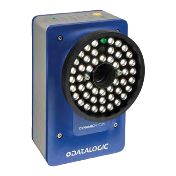
HMI – HUMAN MACHINE INTERFACE AV500/AV900 Versions AV500/AV900 cameras are available in versions that differ depending on the optical res- olution (focus range), F-stop and illumination color. Illumination AV500 P/N Focusing Lens F-stop Color 938000007 Dynamic Focus 16 mm White... -
Page 32: Led Functionality
Solid Green - Good status when camera is running READY The AV500/AV900 LED Boot Sequence 1. All LEDs will turn off after the FPGA is loaded 2. STATUS, COM, GOOD, and TRIGGER LEDs will turn ON after the RTP boots (READY will turn OFF) 3. -
Page 33: X-Press Functionality
X-PRESS FUNCTIONALITY X-PRESS FUNCTIONALITY X-PRESS is the intuitive Human Machine Interface designed to improve ease of installa- tion and maintenance. Status information is clearly presented by means of the five col- ored LEDs, and a single push button gives immediate access to the following relevant functions: •... -
Page 34: Test Mode
In case of a NO READ, only the Status LED is on and it is blinking. To exit the Test Mode, press the X-PRESS push button once. Test Mode will timeout in 4.5 minutes after the last barcode is decoded and revert back to Operating Mode. AV500/AV900 2D CAMERA... -
Page 35: Focus/Locate
If you do not want to accept the learned barcode, let it go and AV500/AV900 will time out. The learned barcode will not be committed. -
Page 36: Default Parameters
“critical” message to the web interface until the default sequence is com- pleted: "Waiting for Xpress Parameter Default to Complete" 10. The following error will be reported if the RTP requests an Xpress default but the COMe does not know about it "Xpress parameter default requested but ignored" AV500/AV900 2D CAMERA... -
Page 37: Accessories
X-PRESS FUNCTIONALITY Accessories The following accessories are available on request for the AV500/AV900 Camera Imag- ing System. Reflecting Mirror P/N 93ACC0086 (380mm) or 93ACC0116 (600mm) The reflecting mirror is used to reduce the footprint of your system. Ethernet Connection Cable (M12-IP67 to RJ45) This cable may be connected to the Host or Image port. - Page 38 Sync-net Connection Cable (M12 male to M12 female) P/N 93A050133 (.75m) P/N: 93A050079 (3m) P/N: 93A050080 (5m) P/N: 93A050081 (10m) I/O Cable (M12-IP67 to CBX) P/N: 93A050059 (3m) P/N: 93A050060 (5m) Power Supply (Single Camera) P/N: 93ACC0058 (US) AV500/AV900 2D CAMERA...
-
Page 39: Communication Ports
The following communication ports are available on the AV500/AV900 camera. Host Network Image Network Sync Net Discrete I/O The AV500/AV900 offers one Digital I/O, which stands for Digital Input and Output. This is available for connection to a CBX which provides multiple additional connections. Dig- PRODUCT REFERENCE GUIDE... -
Page 40: Trigger, Focusing And Position Sensor Devices
In irregular package applications, the photoelectric sensor assists in maintaining the package footprint so that the AV500/AV900 camera will only scan and provide data for a specific package. - Page 41 TRIGGER, FOCUSING AND POSITION SENSOR DEVICES Photoelectric Sensor AS1-HD-HR-010-J D 3M RES 0.5MM H 100MM 958101020 AS1-HD-SR-010-J D 3M RES 5MM H 100MM 958101030 PRODUCT REFERENCE GUIDE...
-
Page 42: 0Lcc-75Xx Kit With Ds2 Light Array
AV500/AV900. The AREAscan™ family of the DS2 series covers controlled heights ranging from 150 to 2500mm, with 5m operat- ing distances for high resolution versions, or 10m for low resolution versions. -
Page 43: Position Sensor
The DK-503 Distance Kit is part of a vision system used to signal the focus range of pack- ages to be imaged by the AV500/AV900 camera. It includes an S85 Class 2 visible red LASER sensor to measure direct proximity from 4 m to 7 m and from 20m to 100m retro- reflective models. -
Page 44: Dm3610 Dimensioner
For complete information about the features and capabilities of the DM3610 Dimen- sioner, see the dimensioner page on the Datalogic website: www.datalogic.com. The DM3610 Dimensioner requires the following: •... -
Page 45: Speed Sensors
SPEED SENSORS SPEED SENSORS Encoder (Tachometer) The encoder/tachometer delivers a continuous pulse to the system, which provides feedback on conveyor speed and transmit point, and can be used to help track the pack- age position along the length of the conveyor. Encoder (Tachometer) OEK-2 OPTICAL ENCODER (CAB 10m+SPRING) 93ACC1770... -
Page 46: Industrial Controllers
CBX Connection Box CBX100 CONNECTION BOX COMPACT 93A301067 CBX510 CONNECTION BOX MODULAR 93A301087 CBX800 GATEWAY 93A301077 Only CBX510 should be used in a system, If additional I/O is needed CBX100 or 800 can be added to other camera systems. AV500/AV900 2D CAMERA... -
Page 47: Sc5000
INDUSTRIAL CONTROLLERS SC5000 Used when multiple cameras are required, the SC5000 Controller offers all the neces- sary functions to make the phases of installation, setup, testing, and maintenance easy and quick. The SC5000 Controller key functions are: • Bus Controller: cluster management and Host interface of a multi-sided reading tunnel •... -
Page 48: Mechanical Installation
It is important that you follow these general precautions when installing, setting up, operating, maintaining, troubleshooting, or replacing any Datalogic products, parts or related equipment. As you plan and install your AV500/AV900 camera imaging system, keep the following guidelines in mind: •... -
Page 49: Mounting Structure Considerations
Datalogic can design one for you. We recommend using a Datalogic mounting structure for standard applications. The AV500/AV900 cannot be mounted parallel to the conveyor belt. A 15 degree angle or more is required to avoid specular reflection. There must be at least 300 mm (12 in) clearance behind the unit for fan air intake! Your mounting structure must provide the following capabilities: •... - Page 50 MECHANICAL INSTALLATION The AV500/AV900 Camera and accessory packaging is designed to protect the unit(s) during shipment. Do not throw it away. Save all packing material in case you need to transport your unit(s) to Datalogic for any reason. 2. Remove the foam layer to 1.
-
Page 51: Complete Installation Sequence
17. Check AV500/AV900 operations MOUNTING Dimensions and Clearances The AV500/AV900 is a sealed, ventilated unit. Mounting the unit with 300 mm [12 in] of clearance (front, top, and sides) is recommended for cooling and ease of maintenance. PRODUCT REFERENCE GUIDE... -
Page 52: Physical Support Requirements
For details on the weight of the cameras, see “Technical Specifications” on page 310. Multiple-head systems may include further details on the physical support require- ments with any application-specific documentation provided. Vibration Limitations See “Technical Specifications” on page 310. AV500/AV900 2D CAMERA... -
Page 53: Mounting And Positioning
60x60 mm profile is recommended for Bosch, although 45x45 mm profiles will work; and standard 1.5” x 3” for 80/20. The following illustrations show the various typical mounting positions for the AV500/ AV900. It is important when mounting the camera that the connector panel is facing away from the conveyor so that the wiring does not interfere with product flow. - Page 54 MECHANICAL INSTALLATION Cameras will only be mounted at 90 degrees when used with a mirror. AV500/AV900 2D CAMERA...
-
Page 55: Mounting Sequence
MOUNTING Mounting Sequence: 1. The AV500/AV900 mounting bracket has two parts and comes assembled. It is packaged with your camera. Bracket M5x12 Button Head Bracket Cap Screws 2. In your mounting kit are the required number of T-bolts and nuts used to attached the mounting bracket to the station frame. - Page 56 MECHANICAL INSTALLATION 4. Set the AV500/AV900 mounting plate in the correct position and tighten the T-bolt nuts. 5. Make sure the bolts holding bracket parts together are loose enough to allow you to rotate the bracket. Once the brackets are in the correction position (15, 30, 45 or 90 degrees) tighten the bolts.
-
Page 57: Installing The Deflection Mirror
INSTALLING THE DEFLECTION MIRROR 7. Attach the nuts to the back of the AV500/AV900. 8. Attach the camera via the four mounting holes by sliding it into place, then tighten the nuts. INSTALLING THE DEFLECTION MIRROR EMK series External Deflection Mirrors are mounted in applications where it is not prac- tical to mount the reader in a position to achieve the full DOF. -
Page 58: Deflection Mirror Bracket Angles
Standard deflection mirror bracket angles are show below. The bolt indicates the locking position between the Main Bracket (blue) and the Rising Bracket (red). The angles spec- ified are reflective angles not the physical angle of the bracket or mirror. AV500/AV900 2D CAMERA... - Page 59 INSTALLING THE DEFLECTION MIRROR Left Back and Right Back (45 degrees) Do not mount the reader so far from the mirror that the reading area extends outside of the mirror surface. It is critical that the brackets do not stress or flex the mirror, as this will cause focusing and calibration issues.
-
Page 60: Left Front And Right Front (15 Degrees)
Rising bracket Aligning the AV500/AV900 with Deflection Mirrors When using deflection mirrors with the AV500/AV900 reader, which is typical, the mir- rors must be mounted parallel to the reader and at the correct distance to allow for proper focus and the highest read rate. Reference the system’s application drawing for distances. -
Page 61: Emk-380 Mounting
INSTALLING THE DEFLECTION MIRROR Deflection mirror is parallel to mirror AV500/AV900 and does not twist Deflection mirrors and readers are perpendicular to the structure rails must line up with The structure is the center of the centered and mirror squared to the... - Page 62 3. Once your bracket is in position, tighten nuts on T-bolts. 4. Mount the mirror rising bracket to the supporting bracket with one bolt in the center position and one bolt in the outer ring. AV500/AV900 2D CAMERA...
- Page 63 INSTALLING THE DEFLECTION MIRROR 5. Rotate the mirror brackets so that the correct skew angle slot as shown on the bracket (15 or 45 degrees). 6. When in position, tighten center and outer ring nuts and attach two additional bolts and nuts in place and tighten as shown in previous diagrams. To prevent mirror bowing or flexing, leave enough play with the rising bracket so if top and bottom (or left and right) brackets are not aligned you do not damage the mirror.
- Page 64 MECHANICAL INSTALLATION AV500/AV900 2D CAMERA...
-
Page 65: Trigger And Focusing Device Mounting
When required, an external device can be used to measure the position of parcels as they enter the field of view of the AV500/AV900 Camera. This information can be used by the camera to determine the correct position for optimal focusing. Proper mounting of these devices is critical to accurately determining the parcel positions. -
Page 66: Electrical Installation
This special documentation supersedes any contradictory content in this manual. To reduce the possibility of damage to the unit, check all cabling between the AV500/ AV900 camera and other devices for accuracy. AV500/AV900 2D CAMERA... -
Page 67: Connecting An Av500/Av900 Camera
To turn off your camera, use a power switch or box. Do not disconnect the 5 pin power connection from the unit. If you attach the power supply to the AV500/AV900 and it is already attached to power, it may cause the AV500/AV900 to not boot correctly. Recycle power by unplugging the AC cord from the power supply and plugging it back in. -
Page 68: Typical Connection Block Diagrams
ELECTRICAL INSTALLATION TYPICAL CONNECTION BLOCK DIAGRAMS See “Standard Interconnection Diagrams INTRODUCTION” on page 326 for more details. Single Head Stand Alone AV500/AV900 AV500/AV900 2D CAMERA... -
Page 69: Single Head Av500/Av900 With Tachometer And Photoeye
TYPICAL CONNECTION BLOCK DIAGRAMS A Controller Key must be connected to I/O port. Single Head AV500/AV900 with Tachometer and Photoeye PRODUCT REFERENCE GUIDE... -
Page 70: Multiple Cameras Connected Via Syncnet In Primary/Secondary Controller Configuration
GENERAL ELECTRICAL INSTALLATION GUIDELINES It is important that you follow these general precautions when installing, setting up, operating, maintaining, troubleshooting or replacing any Datalogic products, parts or related equipment. As you plan and install your barcode reader(s), be sure to keep the following guidelines in mind: •... -
Page 71: Connector Panel
After completing mechanical installation, use this section to properly wire your cameras for optimal performance in your application. AV500/AV900 wiring connections are made to the connector panel and through the CBX connection box (via the AV500/ AV900 I/O port). In most applications, the cable connections to the barcode reader will include: 1. -
Page 72: Connecting A Pc To The Av500/Av900
During initial setup, a PC (laptop) may be connected to the AV500/AV900 with an RJ45 cable. Connect an Ethernet cable from the HOST NET or IMAGE NET port of the AV500/ AV900 to the Ethernet port of your PC. For information on connecting to e-Genius, see “Accessing e-Genius”... -
Page 73: Cbx510 Connection Box
(Ref to ID+) * When working with a slave the jumper is not installed. Although multiple AV500/AV900 cameras can have a CBX box, only one of the CBX boxes in the system can have the Jumper to make it the Master. -
Page 74: Sync In/Sync Out
During initial setup, a PC (laptop) may be connected to the AV500/AV900 with an M12 cable. Connect an Ethernet cable from the HOST NET or IMAGE NET port of the AV500/ AV900 to the Ethernet port of your PC. For information on connecting to e-Genius, see Chapter 4. -
Page 75: Photoelectric Sensor Connections To Cbx510
Barcode scanning applications may use a Datalogic photoelectric sensor as a trigger device. The photoelectric sensor is wired directly into the CBX510 terminal block. If your application uses a trigger other than the one specified by Datalogic, follow the appropriate wiring diagram to assure proper wiring. -
Page 76: Photoelectric Sensor To Cbx510 (Npn)
ELECTRICAL INSTALLATION Photoelectric Sensor to CBX510 (NPN) AV500/AV900 2D CAMERA... -
Page 77: Photoelectric Sensor To Cbx510 (Pnp)
CBX510 CONNECTION BOX Photoelectric Sensor to CBX510 (PNP) PRODUCT REFERENCE GUIDE... -
Page 78: Encoder/Tachometer Wiring To Cbx510
ELECTRICAL INSTALLATION Encoder/Tachometer Wiring to CBX510 Encoder/Tachometer Wiring for NPN Output to CBX510 AV500/AV900 2D CAMERA... -
Page 79: Encoder/Tachometer Wiring For Pnp Output To Cbx510
CBX510 CONNECTION BOX Encoder/Tachometer Wiring for PNP Output to CBX510 PRODUCT REFERENCE GUIDE... -
Page 80: Digital Output Configuration From Cbx510
ELECTRICAL INSTALLATION Digital Output Configuration from CBX510 The CBX510 includes an OUTPUT block for wiring relays as needed for external accesso- ries. Schematics for Isolated and Non-Isolated digital outputs are provided below. AV500/AV900 2D CAMERA... -
Page 81: Unpowered Outputs
CBX510 CONNECTION BOX Unpowered Outputs Powered Outputs PRODUCT REFERENCE GUIDE... -
Page 82: Trigger And Focusing Device Wiring
An external device can be used to measure the position of parcels as they enter the Field of view of the AV500/AV900 Camera. This information is used by the camera to determine the correct position for optimal focusing. The Datalogic focusing devices may be one of the following: •... -
Page 83: Dk503 - S-85 Position Sensor
TRIGGER AND FOCUSING DEVICE WIRING DK503 - S-85 Position Sensor When using the S-85 for focusing, it must be wired to the CBX510 connected to the AV500/AV900 using the cable included in the kit (95ACC1620). PRODUCT REFERENCE GUIDE... -
Page 84: Lcc 75Xx Light Curtain
When using the Datalogic Light Curtain for focusing, it must be wired to the CBX510 connected to the AV500/AV900 using the M12 cable that is part of the cable assembly in the kit. (FOCUS CONTROL SMT CABLE) (93A201203). Cut off the M12 5-pin B-code con-... -
Page 85: Cbx100
Slave units in an array/tunnel will receive their SYNC Network IP addresses from the Master. Although multiple AV500/AV900 cameras can have a CBX box, only one of the CBX boxes in a multi-camera system can have the jumper to make it the Master. -
Page 86: Cbx800
ELECTRICAL INSTALLATION CBX800 Please verify that the CBX800 connection box is configured for the AV500/AV900 appli- cation as follows. 1. Set HOST RS485HD TERM switch to OFF. 2. Set Power Source Selector jumper to FROM SOURCE. 3. Set Shield jumper to FILTERED Earth. -
Page 87: Photoelectric Sensor Connections To Cbx100/800
Barcode scanning applications may use a Datalogic photoelectric sensor as a trigger device. The photoelectric sensor is wired directly into the CBX100/800 terminal block. If your application uses a trigger other than the one specified by Datalogic, follow the appropriate wiring diagram to assure proper wiring. -
Page 88: Photoelectric Sensor To Cbx100 And Cbx800 (Npn)
ELECTRICAL INSTALLATION Photoelectric Sensor to CBX100 and CBX800 (NPN) AV500/AV900 2D CAMERA... -
Page 89: Photoelectric Sensor To Cbx100/Cbx800 (Pnp)
TRIGGER AND FOCUSING DEVICE WIRING Photoelectric Sensor to CBX100/CBX800 (PNP) PRODUCT REFERENCE GUIDE... -
Page 90: As1 Area Sensor To Cbx100/Cbx800 Connections
The AS1 area sensors can detect and provide trigger for very small or irregularly shaped objects. PNP Output. Light Curtain to CBX100/CBX800 Connections The Light Curtain may be connected to the CBX100/CX800 if there is more than one AV500/AV900. AV500/AV900 2D CAMERA... -
Page 91: Encoder/Tachometer Wiring To Cbx100/Cbx800
TRIGGER AND FOCUSING DEVICE WIRING Encoder/Tachometer Wiring to CBX100/CBX800 Encoder/Tachometer Wiring for NPN Output to CBX100/CBX800 Some Photocraft tachometers may have a different color coding: (+V) Red or White/Orange (Signal) White or White/Blue (Ground) Black or Orange/White PRODUCT REFERENCE GUIDE... -
Page 92: Encoder/Tachometer Wiring For Pnp Output To Cbx100/Cbx800
ELECTRICAL INSTALLATION Encoder/Tachometer Wiring for PNP Output to CBX100/CBX800 Some Photocraft tachometers may have a different color coding: (+V) Red or White/Orange (Signal) White or White/Blue (Ground) Black or Orange/White AV500/AV900 2D CAMERA... -
Page 93: Serial Communication Wiring To Cbx100/Cbx800
TRIGGER AND FOCUSING DEVICE WIRING Serial Communication Wiring to CBX100/CBX800 The AV500/AV900 provides serial RS232/RS422 communications to other devices through the CBX100/CBX800. • RS232 provides point-to-point communications at distances up to 15 M [50 ft]. • RS422 provides point-to-point communications at distances up to 1200 M [3940 The following wiring diagrams illustrate the different types of serial communications available via the CBX100 pin block. -
Page 94: Rs422Fd Host (Full Duplex)
The CBX100/CBX500 includes an OUTPUTS block for wiring relays as needed for external accessories. e-Genius Modify | Relays window includes options for outputs 1 and 2 including Life Light, Trigger Output, Error Light, Ready Light, Good Dim, and No Dim. Schematics for Isolated and Non-Isolated relays are provided below. AV500/AV900 2D CAMERA... -
Page 95: Unpowered Outputs
TRIGGER AND FOCUSING DEVICE WIRING Outputs 1 and 2 Maximum Voltage 30V Collector Current (pulse) 130 mA Max. Collector Current (continuous) 40 mA Max. Saturation Voltage (VCE) 1 V at 10 mA Max. Max Power Dissipation 90 mW at 50 degrees C (Ambient temperature) Unpowered Outputs PRODUCT REFERENCE GUIDE... -
Page 96: Powered Outputs
4. Normally, steps 1 through 3 will guarantee proper function. In case of problems such as transmission of strange or wrong characters, devices stop working without any reason, or other unexpected behavior, try connecting the CBX or Controller Earth terminal to the PE terminal inside the PWR box. AV500/AV900 2D CAMERA... -
Page 97: Check Av500/Av900 Installation
TRIGGER AND FOCUSING DEVICE WIRING Check AV500/AV900 Installation After completing the installation, confirm that the AV500/AV900 reader(s) and CBX con- nection box have been properly installed mechanically and electrically. Use the Installa- tion Sequence at the beginning of this chapter and your application specifications to check your installation. -
Page 98: E-Genius
CHAPTER 4 E-GENIUS Datalogic camera imaging systems provide fully automated, industrial quality barcode identification and imaging. The e-Genius web based application provides an easy-to-use series of configuration and diagnostics features that enable you to set up your imaging system. GETTING STARTED e-Genius resides on each camera. -
Page 99: Accessing E-Genius
Contact your IT department to acquire the correct IP address. 1. Connect your computer to the AV500/AV900 HOST NET, IMAGE NET or SYNC NET port using an M12 to RJ45 Ethernet cable. -
Page 100: To Change Your Pc's Ip Address
8. Click Okay. To log out of the e-Genius: Click at the upper right corner of the e-Genius window to Log Out. When logged out, the Log On window will appear. This chapter is a version of that help. AV500/AV900 2D CAMERA... -
Page 101: E-Genius Basics
E-GENIUS BASICS E-GENIUS BASICS e-Genius Menu Tree The functions that you can select are displayed in a menu tree on the left–hand side of e-Genius. The function list is organized much like the hierarchy of a file system, where you can expand items that are preceded by a box ( ) to further sub–levels until you find a function of interest. - Page 102 1. Click the Help icon displayed at the top right of the screen. A help window appears, providing you with information for that specific page. 2. Click the link in the upper left corner of the help window to access Contents options. AV500/AV900 2D CAMERA...
-
Page 103: System Info
SYSTEM INFO System Info provides basic camera system data (whether your system includes one cam- era or an array). View cameras and bring new devices into a cluster (array of cameras and devices that work together). Critical information such as software version, MAC address, and camera position is also provided. -
Page 104: Device Details
Device Details From the System Info window, click on a device’s MAC Address to open a window dis- playing details about that device. The details include statistics, decoder, software, and processor information. AV500/AV900 2D CAMERA... - Page 105 DEVICE DETAILS Camera Statistics Belt Speed Displays the speed of the conveyor belt in millimeters per second or the internal clock for image acquisition. Encoder Frequency Displays the encoder frequency. Statistics Elapsed Time Displays the amount of time elapsed from the last reset or the last modification to the configuration the unit has been collecting statistics.
- Page 106 Identifies the version number of the software PCIe Drive Version Peripheral Component Interconnect Express, better known as PCI Express (and abbreviated PCIe) is a computer expansion card standard used in motherboard-level connections and as an expansion card interface. AV500/AV900 2D CAMERA...
- Page 107 Diagnostic Messages Displays any diagnostic messages that apply. Click on Diagnostics Messages to access the complete list of possible messages. Datalogic Technical Support will use these Diagnostic messages to properly diagnose and troubleshoot your cameras. Real Time Processor (RTP) Details...
- Page 108 SyncNetwork is not connected in a loop, a message will appear when a camera is used as a single stand alone unit. This is not an error and no action is required. When message is in black, it is information only and no action is required. AV500/AV900 2D CAMERA...
-
Page 109: Global Settings
GLOBAL SETTINGS GLOBAL SETTINGS Use the Global Settings menu options to configure your camera system. Configure global settings for any camera and then distribute them to other cameras in the cluster. You can also make modifications to the global system settings, if necessary. “Operating Mode”... -
Page 110: Modify Settings
“Global Settings” on page 89 “Operating Mode” on page 91 “Object Detection” on page 107 “Barcode Settings” on page 111 “Communications” on page 139 “Output Format” on page 151 “Image Saving” on page 160 “Time Synchronization” on page 169 AV500/AV900 2D CAMERA... -
Page 111: Operating Mode
OPERATING MODE OPERATING MODE Use Operating Mode to set up the physical parameters for your system including encoder, trigger, conveyor, and position sensor attributes. There are three major Oper- ating Modes options that are selectable; PackTrack, Online, and Continuous . To edit the system Operating Mode: 1. - Page 112 Select one of the following modes: “Packtrack Mode” on page 93 is a patented operating mode for Datalogic devices used to read and correctly assign codes read on different parcels when placed in the camera reading area at the same time. The technology allows for smaller gaps between packages. It can also be used in bidirectional systems, in which you may want to read codes going forward or reverse.
- Page 113 OPERATING MODE ACKTRACK PackTrack Offset (direction of travel) Enter a value used when a value must be added for proper PackTracking. The PackTrack offset is used to fine tune the PackTrack calibration in the Y-direction (direction of travel). If after the static calibration is complete, the bar code is still not placed on the package correctly, the PackTrack offset parameter allows for a slight adjustment on the Y plane.
- Page 114 (200 tachs per inch/.012700 mm/pulse) used in start/stop applications. Frame Rate Frame Rate Select an appropriate Frame Rate from the drop-down list. This option is adjusted to best fit various applications. Contact Datalogic support to determine the correct setting. • 8 frames per second •...
- Page 115 OPERATING MODE Enter the width of the conveyor. Trigger Source Trigger Source Select from the drop-down list. • Position Sensor: triggers when selected position sensor senses a package. • Photo Sensor: triggers when a photoelectric sensor is blocked. •T rigger Message: triggers when a trigger message is received from an external device.
- Page 116 In a singulated system, a Side-by-Side (SBS) is an error condition in which these conditions are violated. The end-user wants to know when this happens (when their parcel flow has inadvertently become “non-singulated”), and Datalogic systems can tell them this by means of AV500/AV900 2D CAMERA...
- Page 117 Select the check-box to enable placement of the Dimensioning results based on the tachometer. This option works in conjunction with the DM3610 when the Datalogic Message is selected as it's transmit message format. the camera will receive the message at the defined Transmit Point Distance parameter.
- Page 118 Enter the distance (amount of time) before (upstream) of the transmit point when the camera will stop decoding the image data to allow time to get the host message ready to transmit. This will help eliminate processing errors. Green Spot Settings AV500/AV900 2D CAMERA...
- Page 119 When this item is selected, if a spare camera is connected to a tunnel, and it has a newer version of software, it will automatically upload it's software to the other 's in the tunnel. This item should always be unselected unless otherwise instructed by Datalogic. PRODUCT REFERENCE GUIDE...
- Page 120 If the conveyor is slow, and there is a lot of bar codes enabled, the Frame Rate may be reduced so that there is no excess processing load on the camera. •8 frames per second •16 frames per second •24 frames per second •32 frames per second AV500/AV900 2D CAMERA...
- Page 121 Select the check-box to enable placement of the Dimensioning results based on the tachometer. This option works in conjunction with the DM3610 when the Datalogic Message is selected as it's transmit message format. The camera will receive the message at the defined Transmit Point Distance parameter.
- Page 122 Specify the amount of time is milliseconds that the Green Spot should remain on. Redundant Controller Settings Controller Mode: Camera_1 Select one of the following from the drop-down list: Auto-Detect: • This option is used when multiple cameras and CBX’s are used and both can AV500/AV900 2D CAMERA...
- Page 123 Select the check box to enable all cameras in the tunnel to automatically update when software is loaded to one of the cameras. When this item is selected, if a spare AV500 is connected to a tunnel, and it has a newer version of software, it will automatically upload it's software to the other camera's in the tunnel.
- Page 124 When Physical Encoder is Disabled, enter the conveyor speed in meters per second in the field provided (see formula below). When Physical Encoder is Enabled, enter the maximum belt speed using the formula below. Setting the belt speed too high will affect image quality; setting it too low will give you an AV500/AV900 2D CAMERA...
- Page 125 OPERATING MODE exceeded maximum line rate error when the belt exceeds this setting. Formula: Max conveyor speed x 1.05 Advanced Encoder Settings The settings are available when Physical Encoder is set to Enabled above. Direct Encoder Select Disable or Enable from the drop-down list. Direct encoder is a high-resolution encoder/ tachometer used in start/stop applications.
- Page 126 Select the check box to enable all cameras in the tunnel to automatically update when software is loaded to one of the cameras. 3. When you have finished making changes, click Update to save or click Reset to revert to the previously saved values. AV500/AV900 2D CAMERA...
-
Page 127: Object Detection
OBJECT DETECTION OBJECT DETECTION Use Object Detection to set the minimum and maximum size parameters for objects (packages) in your system. To edit the system Object Detection: 1. In the menu tree under Modify Settings, navigate to Global Settings | Object Detection. - Page 128 . However some parcels like cases of water can cause a false identification by the Dimensioner. The Side by Side Verification Settings options allow the AV500/900 to use the bar code data to ignore the SBS message from the dimensioner.
- Page 129 OBJECT DETECTION Table Entry Timeout (min) Enter the amount of time the SBS Condition will be ignored. View Auto Learn Table View Auto Learn Table Click the button and the following table is revealed. GPIN Override Settings GPIN Override Enabled Disabled Select from the drop-down.
- Page 130 Ignore Barcodes Ignore Barcode #N Enter the barcodes to ignore. You can enter up to 25. 3. When you have finished making changes, click Update to save or click Reset to revert to the previously saved values. AV500/AV900 2D CAMERA...
-
Page 131: Barcode Settings
BARCODE SETTINGS BARCODE SETTINGS Use Barcode Settings options to define the barcodes to be read, as well as no read, mul- tiple read and other message characteristics. Make modifications to the system barcode settings using the menu selections: “Barcode Settings Table” on page 112 “Barcode Configuration”... -
Page 132: Barcode Settings Table
Displays the name of the barcode symbology for that index. If no symbology has been added for a row, disabled is displayed. Minimum Length Displays the minimum barcode character length for that row's symbology. Maximum Length Displays the maximum barcode character length for that row's symbology. AV500/AV900 2D CAMERA... - Page 133 BARCODE SETTINGS TABLE Code n Definition Input fields will vary depending on the selected symbology Enable Select the Enable check box to activate the selected barcode. De-select the Enable check box to disable the selected barcode. When the check box has been selected, configuration and code type options are displayed.
- Page 134 Select the check box to enable. Available for Code 128, Code GS1-128, Interleaved 2 of 5, Code 39, Code GS1-128, EAN, UPC, CODABAR, and Code 39. This options allows the bar code to have an illegal quiet zone on one side of the bar code. If selected this could increase the processing time. AV500/AV900 2D CAMERA...
- Page 135 BARCODE SETTINGS TABLE Interleaved 2 of 5 Use Check Digit Select the check box to include the Check Digit in the code transmitted. Check digits can improve decoding safety: it is generally the last digit aligned to the right of the code and verifies the validity of the preceding digits.
- Page 136 Specify the quiet zone in the field provided. This defines the minimum quiet zone (white margins) measured in narrowest module width. This option may be symbology dependent. The quiet zone is expressed as a percentage of module, 500 = 500% of the module = 5 times the module. AV500/AV900 2D CAMERA...
- Page 137 BARCODE SETTINGS TABLE UPC-E Quiet Zone Specify the quiet zone in the field provided. This defines the minimum quiet zone (white margins) measured in narrowest module width. This option may be symbology dependent. The quiet zone is expressed as a percentage of module, 500 = 500% of the module = 5 times the module.
- Page 138 •3: Code positioned both vertically and horizontally Postal Bar Distance (MILS): Enter the distance between bars of the label in inch/1000. It is used to discriminate between expected postal labels and noise, it is the postal label resolution. AV500/AV900 2D CAMERA...
- Page 139 BARCODE SETTINGS TABLE Postal Min/Max Bar Count: Enter the minimum number of bars in the label. It is used for localization purposes (min bars) and for final validation of the label (max bars). QR Code Code Module Size Enter number of code modules in the field provided. Module size is expressed in micrometer (500 micrometer = 0.5 mm) GS1 DataBar Type...
-
Page 140: Barcode Configuration
(up to 10), will all be read in the same reading phase. If the reading phase terminates before all the codes are read, and a No Read message is enabled, Local or Global, a no read message is produced. AV500/AV900 2D CAMERA... - Page 141 BARCODE CONFIGURATION In case of Standard Multi Label, the codes will be distinguished EITHER by their symbol- ogy, OR by their contents. If two (or more) codes share the same symbology and con- tent, the barcode reader will perceive them as a unique code. See “Logical Combination”...
-
Page 142: Single Label
“The Text Entry Tool” on page 81 and enter specific characters to be stripped from the code. Strip Filter Collapse Select the check box to remove the stripped characters from the code and, therefore, reduce the code length (collapsed). AV500/AV900 2D CAMERA... - Page 143 SINGLE LABEL Replacement Char Click to activate the “The Text Entry Tool” on page 81 and enter the substitution character to replace all the stripped ones. It can even be null. 2. When you have finished making changes, click Update to save or click Reset to revert to the previously saved values.
-
Page 144: Standard Multi-Label
The "first decoded bar code" can be different between trigger cycles. When enabled the camera will read all bar codes having the same symbology and number of characters. AV500/AV900 2D CAMERA... - Page 145 STANDARD MULTI-LABEL In order for the multi messages to be transmitted there are several menus that will need to be configured. Enable Send All Multiple Read Labels: First, Multiple Label Separator Next, define a (Standard Formatter): Next, define a Multiple Label Separator (Advanced Formatter), if Advanced Formatter is used: Partial Read Is Treated As When an application is set to read two or more bar codes in a trigger cycle, there are certain decisions that the application software needs to make.
- Page 146 Cancel click to return to origin window without transferring text. 2. When you have finished making changes, click Update to save or click Reset to revert to the previously saved values. AV500/AV900 2D CAMERA...
-
Page 147: Logical Combination
LOGICAL COMBINATION Logical Combination When Logical Combination has been selected from the Code Combination drop-down list, the Barcode Configuration window reveals related input fields. In Logical Combina- tion, you can define groups of codes from the codes set in the Barcode Setting Table which can be read within a trigger cycle. - Page 148 Multiple Read String (max. 128 chars) Click to activate the “The Text Entry Tool” on page 81 and create a string to be displayed in case of Multiple Read Message. AV500/AV900 2D CAMERA...
- Page 149 LOGICAL COMBINATION This parameter is only available when Multiple Read Message is enabled and the No Read Message selection is different from Local No Read(s) String. It is possible to select either the ASCII or HEX value. If disabled, the barcode reader transmits the first code read. Send All Multiple Read Labels Select Enable, Disable from the drop-down list.
-
Page 150: Logical Combination Rules
0) Logical Combination Rules The following are examples of rules used with Logical Combination selection in Barcode Configuration. For all the following examples the No Read Message parameter is set to Global No Read Message. AV500/AV900 2D CAMERA... - Page 151 LOGICAL COMBINATION In all of the examples, Partial must be set to “treat as no read.” Example 1 Code label setting#1 = Code 128 Logical Combination Rule = 1&1 Defines 2 groups, each of them expecting a Code 128 label. Decoded Code Symbology Output Message First Label...
- Page 152 Defines a single group expecting a Code 39 label OR a Code 128 label. Decoded Code Symbology Output Message Label #1 Label #2 <Header><Global No Read Message><Terminator> <Header><Code 39 data><Terminator> <Header><Code 128 data><Terminator> <Header><First decoded code/Multiple Read Mes- sage string ><Terminator> AV500/AV900 2D CAMERA...
- Page 153 <Header><Global No Read Message><Terminator> <Header><Global No Read Message><Terminator> <Header><Code 39 data><DPS>< Code 39 data><DPS>< Code 39 data><Terminator> <Header><Code 39 data><DPS><Code 39 data><DPS><Code 128><Terminator> <Header><Code 39 AV500/AV900 data><DPS><Code 39 AV500/AV900 data><DPS><First decoded code/Multiple Read Message string <Terminator> > PRODUCT REFERENCE GUIDE...
- Page 154 <Header>< Interleaved 2/5 data><DPS>< First decoded code/Multi- ple Read Message string ><Terminator> <Header><Code 93 data><DPS><EAN 8 data><Terminator> <Header><Code 93 data><DPS><UPC-A data><Terminator> <Header><Interleaved 2/5 data><DPS><EAN 8 data><Terminator> <Header><Interleaved 2/5 data><DPS><UPC-A data><Terminator> <Header><First decoded code/Multiple Read Message string><DPS>< First decoded code/Multiple Read Message string ><Terminator> AV500/AV900 2D CAMERA...
-
Page 155: Code Collection
CODE COLLECTION Code Collection 1. When Code Collection has been selected from the Code Combination drop-down list, the Barcode Configuration window reveals related input fields. 2. Enter the appropriate information in the form as described below: Minimum 1D Code Height Enter the minimum code height in the field provided (mm [in]). - Page 156 E-GENIUS 3. When you have finished making changes, click Update to save or click Reset to revert to the previously saved values. AV500/AV900 2D CAMERA...
-
Page 157: Advanced Decode
ADVANCED DECODE Advanced Decode Advanced Decode provides ways to improve read rate, by setting filters or more precise parameters, however these settings often affect processing time. When you set Advanced Decode parameters there is a fine balance between reading performance and processing time. - Page 158 Advanced Localizer Settings Enable Advanced Localizer Select the check box to enable the advanced localizer options. DO NOT change this parameter unless directed by Datalogic Support. Advanced Localizer Usage The camera employs hardware acceleration to locate possible bar codes. This option specifies for which symbologies the hardware acceleration should be used The following parameters allow you to define an ROI or Region of Interest for the decoder.
-
Page 159: Communications
COMMUNICATIONS COMMUNICATIONS Use the Communications Transports window to setup, edit, and configure numbered user sockets or serial ports for your scanning system. User sockets are another interface available for Ethernet communication. There are nine available. Transport parameters are used to setup the serial or Ethernet configuration to match the transmit/receive parameters of an external interface. - Page 160 " option is NOT selected. Camera n Enable Settings Enable Camera Click to enable settings Protocol, see “Data Output Protocol” on page 142 Select one of the following from the drop-down. Serial Options: •Disable •Standard •Advanced •Crisplant •Beumer AV500/AV900 2D CAMERA...
- Page 161 COMMUNICATIONS •Custom 1-5 •Trigger Message Ethernet Options: •Disable •Standard •Advanced •Crisplant •Beumer •Custom 1-5 •Web Sentinel You must select Frame ID or Index for your Image names, if you are sending images to a WebSentinel PLUS Server. This creates unique filenames for each frame, which is nec- essary for capturing frames and saving them with WebSentinel PLUS.
- Page 162 Enter a time value in seconds to define the amount of time between two heartbeat message transmissions. The timeout timer determines the period from one message to the next. In the Conditional setting the timer is reset when either a host message or a heartbeat is sent. In an AV500/AV900 2D CAMERA...
- Page 163 COMMUNICATIONS unconditional condition the heartbeat message timer is only associated with the heartbeat message, not the host message. Header Click to activate the “The Text Entry Tool” on page 81 and create heartbeat header text to signal the beginning of the heartbeat message. Characters from NUL (00H) to ~ (7EH) can be used.
- Page 164 •The Protocol Index message syntax is fixed according to the Crisplant CMC message specifications. Scanner ID Select Datalogic , NVS9000/, Accu-Sort 4800, Accu-Sort 55/70, Accu-Sort Quad-X. Available if Crisplant has been selected. Heartbeat Enable Select the check box to enable Crisplant heartbeat messages. When Crisplant message is selected there is a separate field for the Crisplant heartbeat message.
- Page 165 COMMUNICATIONS Socket Type must be set as TCP Server. Heartbeat Timeout Enter a time value in seconds to define the amount of time between two heartbeat message transmissions. The timeout timer determines the period from one message to the next. In the Conditional setting the timer is reset when either a host message or a heartbeat is sent.
- Page 166 This parameter specifies the distance from the physical Trigger Line (i.e. Trigger Source) to the expected receiving point of the Protocol Index, measured in mm or inches. It is used together with the Minimum Distance Between Two Consecutive Objects (below) parameter to assign AV500/AV900 2D CAMERA...
- Page 167 COMMUNICATIONS the Protocol Index information to the correct package. Distance to Trigger Line State Select Upstream or Downstream. This parameter specifies if the distance from the physical Trigger Line is required Upstream or Downstream (i.e. Trigger Source) to the expected receiving point of the Protocol Index, measured in mm or inches.
-
Page 168: Protocol Index Examples
5. Enter the shared Server port # of the unit generating the protocol index informa- tion and specify Max Clients. 6. Under the Protocol Index Settings - Enable section of the screen, select Without Request Message from the drop-down list. Associated parameters appear. AV500/AV900 2D CAMERA... -
Page 169: Configuration Host Message With Protocol Index
PROTOCOL INDEX EXAMPLES 7. Enter a Header and Terminator for the incoming message from the scale in the fields provided. Use the “The Text Entry Tool” on page 81 to create the Header and Terminator, in this example <STX> and <ETX>. The header and terminator must match the Protocol Index source, in this case, the scale structures. - Page 170 12. Select None from the Item Alignment drop-down. 13. Select Decimal (ASCII) from the Item Data Format drop-down. 14. Select 2 (in this example) from the Transports drop-down list. This was selected as the Idx # in Global Settings | Communications | Transports. AV500/AV900 2D CAMERA...
-
Page 171: Output Format
OUTPUT FORMAT OUTPUT FORMAT Use Output Format to format messages. The following options are available: “Output Format | Standard Formatter” on page 152 “Output Format | Advanced Formatter” on page 155 “Advanced Formatter | Message Builder” on page 157 PRODUCT REFERENCE GUIDE... -
Page 172: Output Format | Standard Formatter
Only the length defined by the Code Field Length parameter is transmitted. Field Length Enter a length value in the field provided. Only for fixed length format. Fill Direction Select Left or Right from the drop-down list. Only for fixed length format. AV500/AV900 2D CAMERA... - Page 173 OUTPUT FORMAT | STANDARD FORMATTER Fill Character For fixed length, click to activate the See “The Text Entry Tool” on page 81 and create a fill character. Code Identifier Disabled, AIM Custom Select , or from the drop-down list. This parameter allows enabling/ disabling the transmission of the code ID in the output data format.
- Page 174 E-GENIUS Custom Code Identifiers 3. When you have finished making changes, click Update to save or click Reset to revert to the previously saved values. AV500/AV900 2D CAMERA...
-
Page 175: Output Format | Advanced Formatter
OUTPUT FORMAT | ADVANCED FORMATTER Output Format | Advanced Formatter Use the Advanced Formatter to set up a selection of advanced code parameters for out- put messages. This is useful when you need to create more complex messages to the Host. - Page 176 “The Text Entry Tool” on page 81 and create Code Identifier characters. 2. When you have finished making changes, click Update to save or click Reset to revert to the previously saved values. AV500/AV900 2D CAMERA...
-
Page 177: Advanced Formatter | Message Builder
ADVANCED FORMATTER | MESSAGE BUILDER Advanced Formatter | Message Builder Use the Message Builder window to configure Advanced system messages. This option allows for the defining of each field in the host message. When Message Builder is activated, Its settings apply to the Advanced Formatter n Item that was being modified in the Advanced Formatter Definition window. - Page 178 Sequence Number: • Indicates the sequential number assigned to the package Hours: • Indicates hour the code was scanned Minute: • Indicates minute the code was scanned Seconds: • Indicates second the code was scanned AV500/AV900 2D CAMERA...
- Page 179 ADVANCED FORMATTER | MESSAGE BUILDER Day: • Indicates day of the month the code was scanned Month: • Indicates month the code was scanned Year: • Indicates year the code was scanned Protocol Index: • Indicates the programmed protocol index string data Length, Width, Height, and Volume are only used if there is a DM3610 in your system.
-
Page 180: Image Saving
To edit the Destination Settings: 1. In the menu tree under Modify Settings, navigate to Global Settings | Image Sav- ing | Destination Settings. The Destination Settings window opens. 2. Enter the appropriate information in the form as described below: AV500/AV900 2D CAMERA... - Page 181 IMAGE SAVING Image Destination List Select the check box(es) corresponding to the numbered image destination to enable setup. Image Index n Destination Settings inputs will appear for the image destinations selected. Image Index n Destination Settings Destination Type Select File System, FTP Server, External Viewer, or On Camera from the drop-down list to save to a remote file system server.
- Page 182 IP Address Enter the IP Address for the FTP Server. Port Number Enter the Port Number where you would like your images to go. Use Global Username Enter a Global username if applicable Username Enter a valid username. AV500/AV900 2D CAMERA...
- Page 183 IMAGE SAVING Password Click to activate the “The Text Entry Tool” on page 81 and enter the password required to access the server. Passive Mode Click the checkbox to enable Passive Mode. File Transfer Timeout Enter an amount of time in seconds within which the transfer of the image will timeout. Destination Directory Enter the complete path of the destination directory.
-
Page 184: Image Settings
Use the Image Settings window to configure where and how images are saved. To edit the Image Settings: 1. In the menu tree under Modify Settings, navigate to Global Settings | Image Sav- ing | Image Settings. The Image Settings window opens. AV500/AV900 2D CAMERA... - Page 185 IMAGE SAVING Image Settings List Select the option button adjacent to the item you wish to create or modify. Image Index n Settings Enable Select the check box to reveal the image settings options. Image Saving Options File Type Select JPEG, Bitmap, or TIFF from the drop-down list. Specifies the type of image to save as. Downsample Select None, 2, 4, 8, or 16 from the drop-down list.
- Page 186 Select a number from 1 to 16 from the drop-down list. With an area camera there may be a large number of images during each trigger cycle. It may be necessary to limit the number of images saved. The Frame Save Criterion allow for the limiting of number of frames saved. AV500/AV900 2D CAMERA...
- Page 187 IMAGE SAVING Image Name Item n Item Type Select an Image Name item type from the drop-down list, including: Parcel ID: • Uses the parcel ID as the Image Name Image Specific String: • Uses the image string entered above Date: •...
- Page 188 Counter shown in Image Name = XX500 (Left Alignment) or 500XX (Right Alignment) Align Filler Char Enter a filler character to use with Align Length. 2. When you have finished making changes, click Update to save or click Reset to revert to the previously saved values. AV500/AV900 2D CAMERA...
-
Page 189: Time Synchronization
TIME SYNCHRONIZATION TIME SYNCHRONIZATION se Time Synchronization to synchronize system time between the system devices. Time must be synchronized for accurate tracking and logging. This feature allows all units within an organization to have the same time stamp. For example, product located on the west coast can have the message stamped with east coast time. -
Page 190: Av500 Device Settings
E-GENIUS AV500 DEVICE SETTINGS Use the Device Settings menu during initial setup to configure device specific settings. If necessary, you can later make modifications to the device settings using the same menu selections, including: “Device Information | Camera #n” on page 172 “Device Settings | Camera #n | Mounting”... -
Page 191: Understanding Packtrack
UNDERSTANDING PACKTRACK UNDERSTANDING PACKTRACK PackTrack is a patented operating mode for Datalogic products used to read and cor- rectly assign codes on different parcels when read at the same time. If the codes of two or more consecutive parcels are found at the same time in the camera reading area, the condition occurs where, the code of the second pack is read first, just before the code of the previous pack. -
Page 192: Device Information | Camera #N
Some examples are: AV900, AV7000. Lens Size Displays the size of the lens; Is it a 16, 25 or 35 mm lens. Lens Aperture Size Displays the Lens Aperture Size; 6, 7, 8 or 9 Sensor Size Displays the Sensor Size; AV500/AV900 2D CAMERA... - Page 193 DEVICE INFORMATION | CAMERA #N Ethernet Ports SyncNet MAC Address Displays the MAC (media access control) address of the cameras SYNC Ethernet port SyncNet IP Address Displays the camera’s SYNC IP address. Image Port MAC Address Displays the MAC Address of the camera’s Image Ethernet Port. Host Port MAC Address Displays the MAC Address of the camera’s Host Ethernet port.
-
Page 194: Device Settings | Camera #N | Mounting
2. Enter the appropriate information in the form as described below: Camera Orientation Mounting Position Top, Left, Right, Bottom Select from the drop-down list depending on where the camera is mounted. This parameter allows defining the installation position of the camera in multi-camera tunnel AV500/AV900 2D CAMERA... - Page 195 DEVICE SETTINGS | CAMERA #N | MOUNTING installations according to the code reading on the conveyor: Top, Right, Left, etc. This parameter acts on the software reading algorithms and on the position and height sensors configuration. Vertical Inversion Camera in Relation to Plant Vertical Inversion Enabled Vertical Inversion Disabled Horizontal Inversion Enabled...
- Page 196 PackTrack label assignment. These are similar to the “extends” that can be applied when not using Position Sensor Data. Used Advanced Label Placement Settings Click the check-box to enable Advanced Label Placement Settings and several other parameters are revealed. AV500/AV900 2D CAMERA...
- Page 197 DEVICE SETTINGS | CAMERA #N | MOUNTING Minimum Across Belt Potion for Placement (left value) / Maximum Across Belt Position for Placement (right value) Normally, for a side read camera, labels are assumed to be in the range from the ‘right side’ of the conveyer (maximum conveyer width) to the left side (0 position).
- Page 198 Load Calibration File Load Calibration File Click to upload the file you have selected. 3. When you have finished making changes, click Update to save or click Reset to revert to the previously saved values. AV500/AV900 2D CAMERA...
-
Page 199: Packtrack Calibration Wizard
PACKTRACK CALIBRATION WIZARD PackTrack Calibration Wizard Use the PackTrack Calibration Wizard to automatically calibrate mounting dimensions and settings. To access the PackTrack Calibration Wizard: 1. In the menu tree under Modify Settings, navigate to Device Settings | <Camera Name> | Mounting. The Mounting window opens. 2. - Page 200 3. Place a Calibration Target at the maximum distance from the camera. Make sure the checker board grid is centered in the green alignment area and the 'Conveyor Direction' arrow is pointing in the direction the conveyor travels. Leave the target under the camera and press 'Next Step'. AV500/AV900 2D CAMERA...
- Page 201 PACKTRACK CALIBRATION WIZARD 4. At the Far Distance, measure along conveyor travel, the distance from the trigger source to the target. 5. At the Far Distance, measure across the conveyor the distance from the target to the edge of the scanning area or the side of the conveyor belt. 6.
- Page 202 11. At the Near Distance, measure up from the conveyor surface to the target, if the target is on the surface of the conveyor, this measurement will be 0. 12. Enter the measurements. AV500/AV900 2D CAMERA...
- Page 203 PACKTRACK CALIBRATION WIZARD 13. Click Next Step and the following screen appears. PRODUCT REFERENCE GUIDE...
- Page 204 14. Click Save and Exit and the following message appears while the values are being saved. 15. When the values have been saved e-Genius will return to the Mounting screen for that camera with the information learned from the Calibration Wizard in the appropriate fields. AV500/AV900 2D CAMERA...
- Page 205 PACKTRACK CALIBRATION WIZARD PRODUCT REFERENCE GUIDE...
-
Page 206: Device Settings | Camera #N | Imaging
Focus Mode Fixed, Dynamic, Dual Zone Sequential Select , or from the drop-down. Focus Settings Imaging Calibration Wizard Imaging Calibration Wizard Click on the button to calibrate Focus and Sensitivity. See “Imaging Calibration Wizard” on page 193. AV500/AV900 2D CAMERA... - Page 207 DEVICE SETTINGS | CAMERA #N | IMAGING IXED OCUS Fixed Focus When mode is selected, enter the fixed focus range in the field provided. This parameter indicates the fixed focus range used when a position sensor is not used. The possible values are from the minimum to the far range.
- Page 208 Dynamic Focus Mode (Imaging Calibration Wizard is not available) Allows the camera to change focus per frame based on data received from a positioning sensor, usually a DM3610. To determine where to focus the AV500/AV900 dynamically, select one of the following from the drop-down: Focus to Center Range: •...
- Page 209 DEVICE SETTINGS | CAMERA #N | IMAGING When Dual Zone focus is selected it allows you to define two zones to which a photo sensor will focus the camera. Zone Photo Sensor to Use Select from the drop-down to Identify which relay input is used to provide the change of focus zone.
- Page 210 E-GENIUS EQUENTIAL When sequential is selected it allows for the AV500/AV900 to read bar codes in two separate zones without the need of a photo sensor. the AV500/AV900 will set two separate focus zones and control the frames it keeps the focus for each zone...
- Page 211 DEVICE SETTINGS | CAMERA #N | IMAGING Gain Settings Profile is selected, a Sensitivity Table offset Factor will adjust the gain according to the focus mode selected. This option is used when position sensor is enabled. Sensitivity Table Offset Factor Sensitivity Table Offset Factor, when used with the Dual Zone Focus Mode option will adjust the gain in the near zone.
- Page 212 Enter a number of pixels Bottom Enter a number of pixels See “Subregion Wizard” on page 200. 3. When you have finished making changes, click Update to save or click Reset to revert to the previously saved values. AV500/AV900 2D CAMERA...
-
Page 213: Imaging Calibration Wizard
IMAGING CALIBRATION WIZARD Imaging Calibration Wizard Use the Imaging Calibration Wizard to automatically calibrate focus and sensitivity for the Fixed, Dual and Sequential focus modes. To access the Imaging Calibration Wizard: In the menu tree under Modify Settings, navigate to Device Settings | <Camera Name> | Imaging. - Page 214 3. You will hear the focusing mechanism as it moves into the optimal focusing posi- tion for the specific camera. 4. Click Save and Exit and the Fixed Focus Range and Sensitivity values are entered into the Imaging parameters based upon the wizard determinations. AV500/AV900 2D CAMERA...
- Page 215 IMAGING CALIBRATION WIZARD Dual Zone Calibration 1. If you have selected Dual Zone focusing, and you click the Imaging Calibration Wizard this is the first screen you will see. Click Next Step>>. 2. Place a Calibration Target, or clean barcode, in the center of the far working range.
- Page 216 Leave the target under the camera and press Next Step>>. 4. Click Save and Exit and the Near and Far Zone Focus Ranges are entered into the Imaging parameters based upon the wizard determinations AV500/AV900 2D CAMERA...
- Page 217 IMAGING CALIBRATION WIZARD Sequential Calibration 1. If you have selected Sequential focusing, and you click the Imaging Calibration Wizard click Next Step>> 2. Place a Calibration Target, or clean barcode, in the center of the far working range. Make sure the checker board grid, or a clean barcode, is centered in the green alignment area.
- Page 218 Leave the target under the camera and press 'Next Step' 4. Click Save and Exit and the Far and Near Focus Ranges are entered into the Image parameters based upon the wizard determinations. 5. You can enter the number of frames as desired. AV500/AV900 2D CAMERA...
- Page 219 IMAGING CALIBRATION WIZARD PRODUCT REFERENCE GUIDE...
-
Page 220: Subregion Wizard
'Conveyor Direction' arrow is pointing in the direction the conveyor travels. Leave the target under the camera. 3. Drag your mouse to select the “Subregion area” you desire. AV500/AV900 2D CAMERA... - Page 221 SUBREGION WIZARD 4. You can click "Update" on the Image Viewer page to transfer the subregion values back to the Imaging page, where you can submit them. 5. Click Update to save the new values as your Subregion. PRODUCT REFERENCE GUIDE...
-
Page 222: Device Settings | Camera #N | Digital Io
Use the Digital IO window to configure the inputs and outputs for the selected camera. To view the Digital IO window: 1. In the menu tree under Modify Settings, navigate to Device Settings | <Camera name> | Digital IO. The Digital IO window opens. AV500/AV900 2D CAMERA... - Page 223 When Enabled the AV500/AV900 will project two red LED's. This is to be used during installation to confirm the center of the AV500/ AV900 image on the scanning surface. It can also be used for presentation applications where...
- Page 224 The Active State allows the AV500/AV900 to accommodate the Active Low/Active High: state of the input signal. Since there are a variety of photo sensors the AV500/900 menu options allows for the camera to change the input state to match the cameras triggering logic.
- Page 225 DEVICE SETTINGS | CAMERA #N | DIGITAL IO 3. When you have finished making changes, click Update to save or click Reset to revert to the previously saved values. PRODUCT REFERENCE GUIDE...
-
Page 226: Device Settings | Camera #N | Serial Port
Global Configuration is selected all camera's in the array can identify the Serial message from the Host/Aux input. This is only available on the camera connected to the CBX Controller. When it is not selected the menu will give the option of selecting a single AV500/AV900 in the array. -
Page 227: Aux Port Settings
Select the check box when using a serial focus device for one or more cameras. When the Use Global Configuration is selected all camera's in the array can identify the Serial message from the Host/Focus input. When it is not selected the menu will give the option of selecting a single AV500/AV900 in the array. Baud Rate Select a value from 1200 to 115200 from the drop-down list. -
Page 228: Device Settings | Camera #N | Ethernet
DNS Address Enter the address of the Secondary Domain Name System (DNS) in the field provided. 3. When you have finished making changes, click Update to save or click Reset to revert to the previously saved values. AV500/AV900 2D CAMERA... -
Page 229: Ethernet | Image Port
DEVICE SETTINGS | CAMERA #N | ETHERNET Ethernet | Image Port Use the Image Port window to set up network communications from the Image Port to a server. To edit the Image Port settings: 1. In the menu tree under Modify Settings, navigate to Modify Settings | Device Settings | Camera N | Ethernet | Image Port. - Page 230 Available only static. IP mode (when DHCP is not selected). Advanced Route Settings Displays the linux command created from the entries into the above fields. 3. When you have finished making changes, click Update to save or click Reset to revert to previously saved fields. AV500/AV900 2D CAMERA...
-
Page 231: Device Settings | Camera #N | Logging
DEVICE SETTINGS | CAMERA #N | LOGGING Device Settings | Camera #n | Logging Use the Logging window to configure how and what information is logged (saved). Once enabled, the logging information will be posted to the Diagnostics Log Viewer (decoder). -
Page 232: Advanced Logging
Advanced Logging can provide advanced data collection for troubleshooting purposes. Contact Datalogic Technical Support for proper use of the Advanced Logging options. To view the Advanced Logging window: 1. From the Logging window, click Advanced Logging. The Advanced Logging win- dow opens. - Page 233 DEVICE SETTINGS | CAMERA #N | LOGGING PRODUCT REFERENCE GUIDE...
- Page 234 E-GENIUS AV500/AV900 2D CAMERA...
- Page 235 DEVICE SETTINGS | CAMERA #N | LOGGING 2. View the following camera information. Basic Logging Click the link to return to the basic Logging window. Verbose Mode Enable Select the check box to verbose logging. When disabled, the debug log will provide data for Critical, Errors, Warnings, and Info in the log text.
-
Page 236: Diagnostics
“Diagnostics | Conveyor View” on page 245 “Diagnostics | Network Diagnostics” on page 247 “Diagnostics | View OnCamera Storage” on page 249 “Diagnostics | Xpress Buttons” on page 251 “Diagnostics | Message Placing Wizard” on page 254 AV500/AV900 2D CAMERA... -
Page 237: Diagnostics | System Status
DIAGNOSTICS | SYSTEM STATUS Diagnostics | System Status Use System Status to get an overview of how your system is running. To access the System Status window: 1. In the menu tree under Diagnostics, click System Status. The System Status window opens. 2. - Page 238 Reset Counts and not inducted any packages yet. The legend changes from “Code Label X” to “Group Label X” when using “Log- ical Combination” as the “Code Combination” setting. AV500/AV900 2D CAMERA...
- Page 239 DIAGNOSTICS | SYSTEM STATUS Show Group Label Statistics Show Group Label Statistics Click to expose these statistics. Hide Group Label Statistics Click to hide this information. Package Information Online indicates the camera is connected to the cluster. Green indicates the camera is not connected to the cluster. Yellow = Online, but not assigned to the cluster (shown under Cameras not in this Cluster) Status...
- Page 240 Identifies the total number of packages with history stored in the camera Camera Statistics Statistics for each system camera are shown in rows with the following columns: Camera Name Displays the camera/device name. Click the device name to view details about that specific device: AV500/AV900 2D CAMERA...
- Page 241 DIAGNOSTICS | SYSTEM STATUS Belt Speed(mm/s) Shown in millimeters per second. Encoder frequency Hz The current encoder frequency computed from the current Belt Speed and the Encoder Resolution. Statistic Elapsed Time Time elapsed from the last reset or the last modification to the configuration of the system. This is reset at startup and when Reset Counts is clicked.
- Page 242 Host Port IP Address Image Port IP Address Configuration Update Count Diagnostic Messages Real-Time Processor Details Displays the following information about the RTP. Software Type Software Version FPGA Version My Decoder’s MAC My Decoder’s IP Total Package Diagnostic Messages AV500/AV900 2D CAMERA...
- Page 243 DIAGNOSTICS | SYSTEM STATUS Diagnostic Messages Diagnostic Messages Click on and a window opens. PRODUCT REFERENCE GUIDE...
-
Page 244: Diagnostics | System Health
Diagnostics | System Health Use the System Health to get specific functional details on each camera in the array. This information will be used by Datalogic support in order to do more in-depth trouble- shooting if necessary. To access the System Health window: 1. - Page 245 DIAGNOSTICS | SYSTEM HEALTH Reviewing the System Health may have an adverse effect on the 's ability to decode bar codes. When the System health is enabled there will be a pop-up identifying this con- cern. PRODUCT REFERENCE GUIDE...
- Page 246 E-GENIUS 3. Select a device from the drop down list to view its Motherboard, Temperature Sensor, Voltage Sensor, System Configuration, Focus Mechanism, Sensor Board and Illumination data. AV500/AV900 2D CAMERA...
-
Page 247: Viewing Camera Images
VIEWING CAMERA IMAGES Viewing Camera Images Use the System Status to view a specific camera’s images. To access the System Status window: 1. In the menu tree under Diagnostics, click System Status. The System Status win- dow opens. 2. Look for image saving information in System Status data as shown below. 3. - Page 248 5. Click |< to move backwards through the available images, >| to move forwards through the available images, or click > to proceed through the images in play mode. 6. Click on any image to select it for the image viewer. AV500/AV900 2D CAMERA...
-
Page 249: Diagnostics | Input/Output Status
Diagnostics | Input/Output Status Use the Input/Output Status window to view whether the PLC is seeing the data com- ing from the camera I/O. The Input 1, Input 2, and Input 3 indicator descriptions vary depending on the Device Setting>Digital IO selections. The Logical Tachometer is an internal clock. -
Page 250: Diagnostics | Serial Comm Status
2. Click Start and the following options display: 3. Click Enable Trigger Source to Position Sensor Calculator. If your Position Sensor is a light curtain, the following view of the Serial Comm Status page appears. AV500/AV900 2D CAMERA... - Page 251 DIAGNOSTICS | SERIAL COMM STATUS 4. Run a single package through the camera tunnel and the calculated Trigger Source to Position Sensor distance is displayed in red. his ability to learn the distance from the Trigger Source to the Position Sensor is useful when the camera is in Packtrack and connected to a tilt belt/cross belt system.
-
Page 252: Diagnostics | Device Tracking
2. Click Start for a continuous feed of Event Type, Seq(uence) Number, Tach(ometer) Count, and Event Information data. 3. Click Stop to pause the feed. 4. Click on a TRANSMIT POINT link to view specific transaction data and image of last package. AV500/AV900 2D CAMERA... - Page 253 DIAGNOSTICS | DEVICE TRACKING Click |< to go to the previous frame. Click > to proceed through the frames Click >| to go to the next frame. PRODUCT REFERENCE GUIDE...
-
Page 254: Diagnostics | Image Viewer
4. Select Live and click Start to view live captured images. The Image Viewer cap- tures an image of the box. The White Level is displayed based on where the cursor is positioned. Toggle the Illumination On/Off. AV500/AV900 2D CAMERA... - Page 255 Choose a higher number to view an image during operation. Contact Datalogic Tech Support before making any calibration adjustments. The White Level field displays the image white level based on where the cursor is posi- tioned.
- Page 256 E-GENIUS 10. Click <ALT> and drag the mouse across the image. 11. The following view of your image light appears. AV500/AV900 2D CAMERA...
- Page 257 DIAGNOSTICS | IMAGE VIEWER 12. Click the Enable Calibration button to reveal sliders which allow you to adjust the Focus, Angle Value and Sensitivity. 13. If your image is not in focus, click on the focus slider to adjust until the image appears in focus.
- Page 258 E-GENIUS AV500/AV900 2D CAMERA...
-
Page 259: Diagnostics | Package Viewer
DIAGNOSTICS | PACKAGE VIEWER Diagnostics | Package Viewer assess package image quality and verify Use the Package Viewer window to view and the PackTrack calibration. To access the Package Viewer window: 1. In the menu tree under Diagnostics, click Package Viewer. The Package Viewer window opens. -
Page 260: Package Details
Click |< to go to the previous frame. Click > to proceed through the frames. Click >| to go to the next frame. The “Canvas” displays a magnified image of a frame. Use the mouse wheel to zoom in/ out on the image. AV500/AV900 2D CAMERA... -
Page 261: Frame Details
DIAGNOSTICS | PACKAGE VIEWER Frame Details Frame Details displays all image frames of a package. When a frame item is clicked a magnified image of the frame is displayed in “Canvas” below it, and detailed informa- tion about this frame is displayed in the “Frame Detail” section. PRODUCT REFERENCE GUIDE... -
Page 262: Diagnostics | Multiple Camera Viewer
Barcodes Out means a decode is not placed on any package. Barcodes Uncertain means it is uncertain which package the decode belongs to (e.g. two packages are too close). AV500/AV900 2D CAMERA... -
Page 263: Diagnostics | Log Viewer
The log view data will only post the data associated with the camera that the GUI inter- face is connected to. It does not post data from other camera's in the tunnel. Contact Datalogic Tech Support to review diagnostic information. 1. In the menu tree under Diagnostics, click Log Viewer (Decoder). The Log Viewer (Decoder) window opens. -
Page 264: Diagnostics | Log Viewer (Rtp)
1. In the menu tree under Diagnostics, click Log Viewer (RTP). The Log Viewer (RTP) window opens. The RTP Log Viewer tool is used by Datalogic support to assist in diagnosing issues experienced by the camera. If a log option is selected, it will remain enabled until it is unselected or power is cycled to the unit. -
Page 265: Diagnostics | Conveyor View
DIAGNOSTICS | CONVEYOR VIEW Diagnostics | Conveyor View Use the Conveyor View window to view a representation of the packages currently on the conveyor. To access the Conveyor View window: 1. In the menu tree under Diagnostics, click Conveyor View. The Conveyor View window opens. - Page 266 E-GENIUS 6. Click Legend to view a color key for the Conveyor View animation. Click Home to return to Modify Settings | System Info. AV500/AV900 2D CAMERA...
-
Page 267: Diagnostics | Network Diagnostics
DIAGNOSTICS | NETWORK DIAGNOSTICS Diagnostics | Network Diagnostics Use Network Diagnostics to diagnose network issues. To access the Network Diagnostics window: 1. In the menu tree under Diagnostics, click Network Diagnostics. The Network Diagnostics window opens. 2. Enter the IP Address of the remote device you want to communicate with and click the ping button to send a message to that device. - Page 268 E-GENIUS AV500/AV900 2D CAMERA...
-
Page 269: Diagnostics | View Oncamera Storage
DIAGNOSTICS | VIEW ONCAMERA STORAGE Diagnostics | View OnCamera Storage Use the View OnCamera Storage window to view stored images on a particular camera within your system. To access the View OnCamera Storage window: 1. In the menu tree under Diagnostics, click View OnCamera Storage. The View OnCamera Storage window opens. - Page 270 E-GENIUS AV500/AV900 2D CAMERA...
-
Page 271: Diagnostics | Xpress Buttons
DIAGNOSTICS | XPRESS BUTTONS Diagnostics | Xpress Buttons Use the Xpress Buttons window to setup Xpress buttons functions within your system. To access the Xpress Buttons window: 1. In the menu tree under Diagnostics, click X-Press Buttons. 2. Select one of the following from the drop-down: •Decode Test •Focus •Setup... - Page 272 Use the aiming laser to aim the camera properly during mounting. Setup Mode will timeout after about 5 minutes. Auto Learn Once entered, the reader starts a procedure to automatically detect and recognize barcode types. The LEARN LED blinks to indicate the Learn mode is enabled. AV500/AV900 2D CAMERA...
- Page 273 If you do not want to accept the learned barcode, let it go and AV500/AV900 will time out. The learned barcode will not be committed.
-
Page 274: Diagnostics | Message Placing Wizard
Calibration The Calibration option allows you to easily find the distance to trigger line value without any calculations. The reference edge and the distance to trigger line state (not for Dimensioner messages) are also found. AV500/AV900 2D CAMERA... - Page 275 DIAGNOSTICS | MESSAGE PLACING WIZARD Follow these steps to calibrate your incoming messages: Enable your Protocol Indexes and/or Dimensioner results. Only enabled messages will show up on the Message Placing Wizard. 1. Click the Calibrate button. 2. Send a package down the conveyor. The message contents should be filled with the first boxes message for each enabled message received.
-
Page 276: Verification Wizard
6. If the resulting value is yellow, we placed on the package, but not in the “accept- able” range. 7. If you click Reset the values will be cleared and you will need to begin the Calibra- tion process over again. AV500/AV900 2D CAMERA... -
Page 277: Utilities
UTILITIES UTILITIES Use the Utilities Menu selections to backup and restore system parameters, upgrade system software, or download system log information using the following selections: “Utilities | Advanced Cluster Configuration” on page 258 “Utilities | Backup/Restore Parameters” on page 260 “Utilities | Software Upgrade”... -
Page 278: Utilities | Advanced Cluster Configuration
The Advance Cluster option allows for the repositioning of the camera. DO NOT use Advanced Cluster Configuration unless authorized by Datalogic Support. Using this function without Datalogic Support can harm system operation. To access the Advanced Cluster Configuration window: 1. - Page 279 UTILITIES | ADVANCED CLUSTER CONFIGURATION When the Swap 2. Click Swap Cameras. The selected camera’s swap MAC addresses. Cameras is selected the system will assume the parameters associated to the other camera. It will then change the XML (parameter) file by placing it's MAC address in the new location and send the updated XML file to the other cameras in the cluster.
-
Page 280: Utilities | Backup/Restore Parameters
You must only restore a system with a restore file originally created from that system. DO NOT use a restore file from a different system. NEVER use on a configured system. 4. Click Load Parameter File to upload the file to the system device(s). AV500/AV900 2D CAMERA... - Page 281 UTILITIES | BACKUP/RESTORE PARAMETERS To Download a Partial Parameter file: 1. Click Partial Download to download a partial parameter file. 2. Click the check-boxes for the parameters you wish to include in the file. 3. Click Create Partial Parameters button and the file will be created. 4.
- Page 282 4. Click Submit to save the new password. The following confirmation message appears. 5. Click OK to reset the password for ALL cameras in this cluster or Cancel. When the password has been successfully reset, the following message appears. AV500/AV900 2D CAMERA...
-
Page 283: Utilities | Software Upgrade
UTILITIES | SOFTWARE UPGRADE Utilities | Software Upgrade Use the Software Upgrade window to load new versions of the camera system soft- ware. Please clear the PC’s browser cache regularly or set up the browser to disable caching altogether. This is especially important after software upgrades to make sure updates in e-Genius are visible. - Page 284 8. Click RTP Operating System history to view RTP (Real Time Processing) software revision historical information about the Real Time Processing OS. 9. Click Download to save a copy of the installed software to your PC. AV500/AV900 2D CAMERA...
-
Page 285: Utilities | Download Logs
UTILITIES | DOWNLOAD LOGS Utilities | Download Logs Use Download Logs window to download system information logs to your PC. To use the Download Logs function: 1. In the menu tree under Utilities, click Download Logs. The Download Logs win- dow opens. -
Page 286: Utilities | Download Tools
2. Click on a link to download the indicated tool to your computer. Live Image Viewer 1. Click Live Image Viewer to download the tool. Extract the tool to your desired location. Click on the exe to open. The following window opens. AV500/AV900 2D CAMERA... -
Page 287: Packtrack Target (Letter) And (A4)
UTILITIES | DOWNLOAD TOOLS PackTrack Target (Letter) and (A4) 1. Click PackTrack Target and the following target will display. 2. Click the printer icon to print the target to be used for calibration purposes. PRODUCT REFERENCE GUIDE... -
Page 288: Utilities | Camera Reboot
1. In the menu tree under Utilities, click Camera Reboot. The Camera System Options window opens. 2. Click Camera Reboot and the following confirmation message appears. 3. Click OK to continue the camera reset or Cancel to discontinue this process. AV500/AV900 2D CAMERA... -
Page 289: Utilities | Help And Logout
UTILITIES | HELP AND LOGOUT Utilities | Help and Logout Utilities | Help Use the Help selection to access the online help system. In the menu tree under Utilities, click Help. The online help Welcome page opens in a new browser window. Utilities | Logout Click Utilities | Logout to exit e-Genius. -
Page 290: Trigger, Positioning And Focusing Device Setup
TRIGGER, POSITIONING AND FOCUSING DEVICE SETUP The AV500/AV900 trigger and focusing position is computed by the camera based on the position of the package measured by a trigger and/or focusing device. These Data- logic devices may be one or more of the following: •... -
Page 291: First-Time Startup
There are several Datalogic focusing options available for the AV500/AV900. Each option serves a different purpose in AV500/AV900 systems. They can be used alone or in combination with one another. Below is a list of the available options and an explana- tion of their purpose. -
Page 292: Dm3610 Dimensioner
Reference the S-60 Installation Guide (included with your S-60 kit) for complete infor- mation on connecting and aligning the Photocell. Make the following selections in the AV500/AV900 e-Genius application Operating Mode. SETTING UP THE AS1 AREASCAN Reference the AS1 Series Instruction Manual (included with your AS1 kit) for complete information on connecting and aligning the ASl. -
Page 293: Setting Up The Ds2 Light Curtain
SETTING UP THE DS2 LIGHT CURTAIN SETTING UP THE DS2 LIGHT CURTAIN Reference the DS2 Instruction Manual available at www.datalogic.com for complete information on connecting and aligning the Light Curtain. Make the following selections in the AV500/AV900 e-Genius application Operating Mode. - Page 294 TRIGGER, POSITIONING AND FOCUSING DEVICE SETUP Change to Disabled! Must be set to Photo Sensor Change to 0! 3. In the menu tree under Device Settings, click Serial > Foc us/Host Port. The Focus/ Host Port window opens. AV500/AV900 2D CAMERA...
- Page 295 SETTING UP THE S85 PHOTOSENSOR 4. Set the Focus/Host Port parameters as shown below:. This will need to be done for each camera an S85 is connected to. 5. Click Update to save your changes. 6. In the menu tree under Diagnostics , click Serial Comm Status . The Serial Communi- cations Status window opens.
-
Page 296: Setup And Calibration
1. In e-Genius under Modify Settings, navigate to Global Settings / Operating Mode. The Operating Mode window opens. 2. Select the Photo Sensor as Trigger Source from the drop-down. 3. Select the Position Sensor Type from the drop-down. Select S85 or S85 with DL Light Curtain. AV500/AV900 2D CAMERA... - Page 297 SETTING UP THE S85 PHOTOSENSOR 4. Enter the Position Sensor Transmit Delay as 127mm. This is required because the tach controller camera (with or without an S85 connected) tracks the connected S85’s and DL light curtain to a point that is 127mm past the S85/LC that’s located the furthest downstream from the PE (and closet to the first camera scanline).
-
Page 298: Setting Up The Dm3610 Dimensioner
The Dimensioner scan line must be installed at least 500 mm [20 in] upstream from the nearest camera scan line. The examples used in this guide use Imperial units i.e. inches. AV500/AV900 If the sys- tem is configured for metric, the unit of measure will be in mm. -
Page 299: Preparation
AV500/AV900 (typically Main, consult your application interconnect diagrams for details). The Serial | Main window opens. 2. Make sure the selected Baud Rate matches that of the AV500/AV900 (uses the main port, RS485 (RS422), at 115200). - Page 300 The DM3610 Left and Right Offsets will focus the DM3610 at the Far Working Distances (Left and Right) of the side AV500/AV900 cameras. These values are not necessarily the same. AV500/AV900 Reference the system application drawings for the exact prescribed Far Working Distances of each camera.
-
Page 301: Adjusting Dm3610 Left Focus Offset
1. Position a test box with a known width in the dimensioner line(s) so the side of the box is at the RIGHT side AV500/AV900 far working distance as specified by the application’s installation drawing. In this example we will be using a box with a 3”... - Page 302 4. Subtract the width of the test box, in our example it is 3”, from the value displayed for Left. 4.25 – 3 = 1.25 5. Enter the result as a NEGATIVE value in the Left Offset field. In this case you will enter -1.25. AV500/AV900 2D CAMERA...
-
Page 303: Adjusting Right Focus Offset
SETTING UP THE DM3610 DIMENSIONER 6. The position value displayed for the Left is now 3. 7. Click Update to save your changes. Adjusting Right Focus Offset When working with a DC3000 multi-head based Dimensioning system, the text box must intercept all dimensioning lines. 1. - Page 304 3. Subtract the width of the test box from the value displayed for RIGHT. 6.5 – 3 = 3.5 4. Enter the result into the RIGHT OFFSET field as a negative value, in our example it is -3.5. 5. Note the position value displayed for RIGHT is now 3. AV500/AV900 2D CAMERA...
-
Page 305: Adjusting Height Offset
6. Click Update to save the changes. 7. Test the system by inducting a series of application objects and bar codes. Use the AV500/AV900 imaging utility to verify that the cameras are focusing properly over the width and height of the conveyor. -
Page 306: Calibration
CHAPTER 6 CALIBRATION The AV500/AV900 Camera can be set up as a single unit or with multiple units in a scan- ning array (tunnel). The AV500/AV900 camera system is a high-precision imaging sys- tem, and requires careful and accurate setup and calibration to function at its full potential. -
Page 307: E-Genius Calibration Presets
3. Click Update to add the camera to the This Cluster table. 4. Once each AV500/AV900 has been added under This Cluster, its mounting posi- tions will need to be identified. Click Blink in a camera’s row in the table. That camera’s illumination will light. -
Page 308: Device Settings
There will be a different Device Settings branch in the menu tree for each camera in an array. See section “AV500 Device Settings” on page 170 for an explanation of the Device Settings options. 1. In the menu tree, navigate to Modify Settings | Device Settings | Camera N | Device Info. -
Page 309: Static Calibration
SOFTWARE UPDATE Static Calibration Static calibration is used to set up and calibrate the camera while the conveyor is sitting still. 1. Navigate to Modify Settings | Device Settings | Camera N | Mounting. The Mounting window opens. See “Device Settings | Camera #n | Mounting” on page 174. - Page 310 CALIBRATION If you are calibrating side read cameras place your calibration target as show in the dia- grams below. AV500/AV900 2D CAMERA...
- Page 311 SOFTWARE UPDATE Left Side Right Side 3. Place a calibration target at the maximum distance from the camera. Make sure the checker board grid is centered within the green alignment area. Make sure the Conveyor Direction arrow is pointing in the direction in which the conveyor is trav- eling.
- Page 312 Calibration Target. 7. Measure the distance from the conveyor surface to the Calibration Target. Z=0 8. Enter those measurements into the Far Measurements fields. 9. Click Next Steps >>. 10. Step 3/5: Near Distance Calibration Target Alignment appears: AV500/AV900 2D CAMERA...
- Page 313 SOFTWARE UPDATE 11. Place a target at the minimum distance and measure X, Y, and Z references •X is the distance from the side of the belt to the Calibration Target. •Y is the distance from the Photo Sensor or Position Sensor, which ever is closer to the camera, to the Calibration Target.
- Page 314 CALIBRATION AV500/AV900 2D CAMERA...
-
Page 315: Online Calibration
SOFTWARE UPDATE 14. Check the values for far distance and near distance. 15. Click Save and Exit button. 16. Verify! Online Calibration The following procedure is for Online Mode. Operating Mode In the menu tree under Modify Settings, navigate to Global Settings | Operating Mode. The Operating Mode window opens. - Page 316 Sequential focusing. 2. Than click Imaging Calibration Wizard and follow the instructions. 3. Place a target at the desired focusing distance and click >>Next Step. The camera will begin to find the correct focusing distance as shown below. AV500/AV900 2D CAMERA...
- Page 317 SOFTWARE UPDATE 4. When the camera has completed this step it will show the Fixed Focus Range and Fixed Sensitivity values. 5. Click Save and Exit to complete the calibration process and the values will be transferred to the Imaging window. 6.
-
Page 318: Other Camera Checks
If the WebSentinal software is mounted on a customers server the destina- tion directory may be different. One of the greatest advantages of using WebSentinel PLUS with the AV500 is the ability to save all of your camera images. - Page 319 SETTING THE AV500/AV900 TO COMMUNICATE WITH WEBSENTINEL PLUS 1. In the e-Genius menu under Modify Settings, select Global Settings >Image Sav- ing > Destination Settings, the Image Destination Settings window opens. 2. Enable Image Destination 1 or the next available.
-
Page 320: Set Up The Image Saving Options
One of your Image Name Item > Item Types must be set to Frame Index as show above. This is required so that each frame is saved as a unique image with a unique filename, therefore assuring that frames are not saved over-top of one another. AV500/AV900 2D CAMERA... -
Page 321: Define Transport Settings
SETTING THE AV500/AV900 TO COMMUNICATE WITH WEBSENTINEL PLUS 3. Click Update to save the changes. Define Transport Settings 1. In the menu tree under Modify Settings, select Global Settings > Communica- tions > Transports. The Transport List Settings window opens. -
Page 322: Maintenance
Use to clean illumination exit window Due to the complex and application-specific nature of these installations, AV500/AV900 camera systems must be setup and serviced by authorized technicians trained by Datalogic. Maintenance procedures in this chapter may be performed by an end user technician. Train- ing is recommended if the end user intends to do more than the maintenance procedures provided in this chapter. -
Page 323: Recommended Maintenance Frequency
RECOMMENDED MAINTENANCE FREQUENCY RECOMMENDED MAINTENANCE FREQUENCY The AV500/AV900 Camera System is designed for industrial environments. The recom- mended frequency for performing these maintenance tasks will depend on the applica- tion’s environment. In general, these procedures are recommended only if it is noticed... -
Page 324: Cleaning The Deflection Mirror
5. Use a dry, soft, lint-free cloth to remove accumulated dust. 6. If the deflection mirror is particularly dirty or smudged, make a solution of seven parts denatured alcohol and three parts water. (Many over-the-counter solutions will leave deposits/smudges that can affect performance.) AV500/AV900 2D CAMERA... -
Page 325: Cleaning The Photoelectric Sensor
MAINTENANCE TASKS 7. Apply the cleaning solution to a lint-free cloth. 8. Apply the cloth with the cleaning solution to the mirror. 9. Remove any streaks or remaining moisture from the mirror with a dry, soft, lint- free cloth or lens paper. 10. -
Page 326: Tighten Mounting Hardware
If after performing maintenance, the imaging system continues to perform below the normal operations experienced with the system under normal daily conditions, contact Datalogic through our website at www.datalogic.com. Verify Photoelectric Sensor Operation 1. Block the Photoelectric Sensor emitter beam to confirm it is aligned properly with the reflector. -
Page 327: Verify Tachometer Operation
The fan of the AV500/AV900 is a field replaceable part. Request spare part number: 8900006713. Instructions are included. Replacing the SD Card If you are replacing a non-working AV500/AV900 in your array, remove the SD card from a non-working AV500/AV900 and insert into the new unit. Follow these steps: Tools Required 2.5 mm T Hex Wrench... - Page 328 Remove the SD Card by lightly pushing in the card which will then pop out. Replace the existing SD card with the new one and push to insert the new card. Close the hinged door and re-tighten the screw. AV500/AV900 2D CAMERA...
-
Page 329: Technical Features
CHAPTER 8 TECHNICAL FEATURES This chapter provides detailed specifications for the AV500/AV900 Camera Systems. It provides specific information on: • Electrical Features • Optical Features • Reading Features • Human Machine Interface • Software Features • Environmental Features • Physical Features... -
Page 330: Technical Specifications
Integrated Red or White SCAN ENGINE 2D Ultra slim area imager (supports 1D/2D codes): Datalogic’s Green Spot for good-read feedback Depth of Field: 8.5 to 50 cm / 3.3 to 19.7 in. depending on bar code density and type 5 Mp - 2448 x 2048 pixels... - Page 331 TECHNICAL SPECIFICATIONS Supply Voltage 24 VDC +/- 20% Power Consumption PHYSICAL CHARACTERISTICS Dimensions 20.0 x 12.6 x 13.0 cm / 7.8 x 4.9 x 5.1 in Weight 2,900 g / 6.4 pounds Chassis Material A380 Die Cast Aluminum ENVIRONMENTAL FEATURES Humidity 95% non condensing Protection Class...
-
Page 332: Av500 Reading Features
AV500 READING FEATURES FOV Calculation Use the data in the following tables to calculate the FOV for your application. AV500 Range is measured from the back of the unit. AV500 FOV = 2*[(D-X)*tan(a/2)] Range is measured from the back of the unit 15 degree angle, 16mm., 1.1 PPM 0.2MM... - Page 333 AV500 READING FEATURES 0.2MM 0.25M 0.3MM 0.33M 0.38M 0.5M M, 10 , 12 M, 13 M, 15 M, 20 Range Range Range Range Range Range Near Left 1402 -214 1730 -268 2056 -322 2252 -354 2580 -408 2600 -411 Left...
-
Page 334: (Av500) 5 Megapixel Reading Diagrams
Data Matrix ECC 200 (2D code) from the Test Charts provided with the reader. • Testing should be performed with the actual AV500/AV900 using application codes in order to evaluate whether maximizing application performance requires adjust- ments to the HW/SW configuration with respect to the Reference Conditions given under each diagram. -
Page 335: White Illumination 16 Mm
(AV500) 5 MEGAPIXEL READING DIAGRAMS White Illumination 16 mm Range is measured from the back of the unit Camera mounted at a 15 degree angle Read area is for 1D codes at a minimum 1.1 Pixel per element PRODUCT REFERENCE GUIDE... -
Page 336: 16Mm F6 Application Example
TECHNICAL FEATURES 16mm F6 Application Example 20 mill code 128 640mm FOV 750mm DOF Focus set to 1800mm Belt speed 1 m/s AV500/AV900 2D CAMERA... -
Page 337: White Illumination 25 Mm
(AV500) 5 MEGAPIXEL READING DIAGRAMS White Illumination 25 mm Range is measured from the back of the unit Camera mounted at a 15 degree angle Read area is for 1D codes at a minimum 1.1 Pixel per element PRODUCT REFERENCE GUIDE... -
Page 338: 25Mm F8 Application Example
TECHNICAL FEATURES 25mm F8 Application Example 12 mill code 128 400mm FOV 600mm DOF Focus set to 1725mm Belt speed 1 m/s AV500/AV900 2D CAMERA... -
Page 339: 25Mm F7 Application Example
(AV500) 5 MEGAPIXEL READING DIAGRAMS 25mm F7 Application Example 13 mill code 128 520mm FOV 450mm DOF Focus set to 2150mm Exposure offset - 140us Belt speed 2.5 m/s PRODUCT REFERENCE GUIDE... -
Page 340: White Illumination 35 Mm
TECHNICAL FEATURES White Illumination 35 mm Range is measured from the back of the unit Camera mounted at a 15 degree angle Read area is for 1D codes at a minimum 1.1 Pixel per element AV500/AV900 2D CAMERA... -
Page 341: 35Mm F8 Application Example
(AV500) 5 MEGAPIXEL READING DIAGRAMS 35mm F8 Application Example 10 mill code 128 640mm FOV 750mm DOF Focus set to 1800mm Belt speed 1 m/s PRODUCT REFERENCE GUIDE... -
Page 342: Av900 9 Mega Pixel Read Charts
Range is measured from the back of the unit, horizontal view Camera mounted at a 15 degree angle Read area is for 1D codes at a minimum 1.1 Pixel per element Objects are conveyed 25 mm 1.1 PPE AV500/AV900 2D CAMERA... - Page 343 AV900 9 MEGA PIXEL READ CHARTS 35 mm 1.1 PPE PRODUCT REFERENCE GUIDE...
- Page 344 TECHNICAL FEATURES 25 mm App Example1 AV500/AV900 2D CAMERA...
- Page 345 AV900 9 MEGA PIXEL READ CHARTS 35 mm App Example1 PRODUCT REFERENCE GUIDE...
-
Page 346: Standard Interconnection Diagrams Introduction
APPENDIX A STANDARD INTERCONNECTION DIAGRAMS INTRODUCTION The AV500/900 supports innumerable configurations. Illustrated here are eight typical examples. AV500, Distance Sensor, CBX510, Trigger and Tachometer AV500/900 cameras cannot accommodate fieldbus, however a CBX800 can be used for fieldbus applications. AV500/AV900 2D CAMERA... -
Page 347: Av500, Light Curtain, Cbx510, Trigger And Tachometer
STANDARD INTERCONNECTION DIAGRAMS INTRODUCTION AV500, Light Curtain, CBX510, Trigger and Tachometer AV500/900 cameras cannot accommodate fieldbus, however a CBX800 can be used for fieldbus applications. PRODUCT REFERENCE GUIDE... - Page 348 APPENDIX A Two AV500s, Distance Sensor, CBX510, CBX100, Trigger, Tachometer AV500/900 cameras cannot accommodate fieldbus, however a CBX800 can be used for fieldbus applications. AV500/AV900 2D CAMERA...
-
Page 349: Two Av500S, Distance Sensor, Cbx510, Cbx100, Trigger, Tachometer
STANDARD INTERCONNECTION DIAGRAMS INTRODUCTION Two AV500s, Light Curtain, CBX510, CBX100, Trigger, Tachometer AV500/900 cameras cannot accommodate fieldbus, however a CBX800 can be used for fieldbus applications. PRODUCT REFERENCE GUIDE... -
Page 350: Two Av500S, Light Curtain, Cbx510, Cbx100, Trigger, Tachometer
APPENDIX A Two AV500, Light Curtain, Distance Sensor CBX510, CBX100, Trigger, Tachometer AV500/900 cameras cannot accommodate fieldbus, however a CBX800 can be used for fieldbus applications. AV500/AV900 2D CAMERA... -
Page 351: Two Av500, Light Curtain, Distance Sensor Cbx510, Cbx100, Trigger, Tachometer
STANDARD INTERCONNECTION DIAGRAMS INTRODUCTION Three AV500’s, Light Curtain, Distance Sensor CBX510, CBX100, Trig- ger, Tachometer AV500/900 cameras cannot accommodate fieldbus, however a CBX800 can be used for fieldbus applications. PRODUCT REFERENCE GUIDE... -
Page 352: Three Av500'S, Light Curtain, Distance Sensor Cbx510, Cbx100, Trigger, Tachometer
APPENDIX A Three AV500’s, Light Curtain, Two Distance Sensors CBX510 and CBX100, Trigger and Tachometer AV500/900 cameras cannot accommodate fieldbus, however a CBX800 can be used for fieldbus applications. AV500/AV900 2D CAMERA... -
Page 353: Three Av500'S, Light Curtain, Two Distance Sensors Cbx510, Cbx100, Trigger And Tach
STANDARD INTERCONNECTION DIAGRAMS INTRODUCTION Four AV500’s, Light Curtain, Two Distance Sensors CBX510, CBX100, Trigger, Tachometer AV500/900 cameras cannot accommodate fieldbus, however a CBX800 can be used for fieldbus applications. PRODUCT REFERENCE GUIDE... -
Page 354: Ethernet/Ip Configuration In Reader
Output data with other EIP enabled devices, such as a programmable logic controller (PLC). Software release 1.4.0.0 and higher for the AV500/900 product line supports the legacy ASI EtherNet/IP™ Object. This mode allows the installation of AV500/900 cameras in systems using PLC programs developed for Axiom, Axiom X, and AL5010 scanners and can also be useful if ControlLogix On-Demand Messaging is desired for an application. -
Page 355: Ethernet Ip Introduction
ETHERNET IP INTRODUCTION 3. Click the Socket Type drop-down and select Ethernet/IP, various Ethernet options will appear. PRODUCT REFERENCE GUIDE... - Page 356 By contrast, On-Demand Messaging (which only works with a ControlLogix Controller) allows bar code data to be sent to the Controller only when a bar code is read. AV500/AV900 2D CAMERA...
- Page 357 ETHERNET IP INTRODUCTION Select the check-box Enable ControlLogix On-Demand. This is described in more detail later in this document. The Message Format parameters allow you to manipulate the format of the bar code data. Most notable if your barcodes only contain numeric digits, you can configure the reader to convert the bar codes to a numeric value instead of transmitting them as ASCII text.
- Page 358 APPENDIX B The Digital Output Lines parameter can be used to relinquish control of the internal relays (2 relays for AV500/900). When this has been done, these relays are controlled by bits within the Output Word. Lastly, When EIP is enabled, the option Start Input From Bus becomes available on the Operating Mode page of e-Genius.
- Page 359 ETHERNET IP INTRODUCTION When this is enabled, the camera trigger input is ignored and the reader will be trig- gered solely by manipulating the Trigger Bit in the Output Word (contained in the reader Assembly and Output Objects). PRODUCT REFERENCE GUIDE...
- Page 360 When EtherNet/IP is enabled on the camera, EIP I/O Messaging is automatically enabled. No further configuration on the Datalogic device is needed to setup I/O mes- saging. Since the ControlLogix processor now treats the camera as an I/O device, to...
-
Page 361: I/O Controllogix Messaging Example
I/O CONTROLLOGIX MESSAGING EXAMPLE 3. Specify the Properties for your camera. First set the Comm Format to Data-INT. This must be done first as it cannot be changed later. 4. Specify the Name, Description and IP address of the camera. 5. - Page 362 Bar Code Sequence Number” (see Output Data) is set equal to this value. Reader:I.Data[2] Bar Code Status Not currently used. Number of words which contain Reader:I.Data[3] Bar Code Size (words) the barcode data Reader:I.Data[4-67] Bar Code Data AV500/AV900 2D CAMERA...
- Page 363 I/O CONTROLLOGIX MESSAGING EXAMPLE Discrete Input Word Unused Unused Unused Unused Unused Unused Unused Unused 8-15 Unused Reader:O Output Data Tag Name Value Description Reader:O.Data[0] Discrete Output Word See bit definitions. This field must be updated to Last Barcode Sequence Num- match the Bar Code Sequence Reader:O.Data[1] ber Received...
-
Page 364: I/O Messaging Ladder Logic Example
For On-Demand messaging follow these steps: 1. To enable the camera, select the check-box Enable ControlLogix On-Demand Messaging from the Ethernet/IP page within e-Genius. AV500/AV900 2D CAMERA... -
Page 365: On-Demand Messaging (Controllogix)
I/O CONTROLLOGIX MESSAGING EXAMPLE 2. Specify the IP address and slot for the ControlLogix processor. 3. Name of the Tag to contain the bar code data. Once this is complete, you need to define a new Tag in the ControlLogix processor. The new tag must have a type of INT and a dimension of 67 words. - Page 366 The following table has a description of all of the data types used. USINT Unsigned Short Integer (8-bit) UINT Unsigned Integer (16-bit) UDINT Unsigned Double Integer (32-bit) STRING Character String (1 byte per character) BYTE Bit String (8-bits) WORD Bit String (16-bits) DWORD Bit String (32-bits) AV500/AV900 2D CAMERA...
-
Page 367: Standard Objects
I/O CONTROLLOGIX MESSAGING EXAMPLE STANDARD OBJECTS Identity Object (01HEX - 1 Instance) Class Attributes Attribute ID Name Data Type Data Value Access Rule Revision UINT Instance Attributes Attribute ID Name Data Type Data Value Access Rule Vendor Number UINT 25DEC Device Type UINT 00HEX... -
Page 368: Assembly Object (04Hex - 4 Instances)
8-15 Unused Instance 0x70 Attributes (Output Instance 1) Default Attribute ID Name Data Type Access Rule Data Value Output Data Structure of: UINT Discrete Output Word Get / Set (see below) UINT Last Barcode Seq. Num Received AV500/AV900 2D CAMERA... -
Page 369: Connection Manager Object (06 Hex)
I/O CONTROLLOGIX MESSAGING EXAMPLE Discrete Output Word Bit = 0 Bit = 1 Trigger Off Trigger On 1 – 7 Unused Unused Reader Relay #1 Off Reader Relay #1 On Reader Relay #2 Off Reader Relay #2 On Reader Relay #3 Off Reader Relay #3 On Reader Relay #4 Off Reader Relay #4 On... -
Page 370: Common Services
STRING Host Name Common Services Service Code Implemented for Service Name Class Level Instance Level Get_Attribute_Sin- 0EHEX Ethernet Link Object (F6 - 1 Instance) Class Attributes Attribute ID Name Data Type Data Value Access Rule Revision UINT AV500/AV900 2D CAMERA... -
Page 371: Vendor Specific Objects
I/O CONTROLLOGIX MESSAGING EXAMPLE Instance Attributes Default Attribute ID Name Data Type Access Rule Data Value Interface Speed UDINT Interface Flags DWORD Physical Address USINT Array[6] Common Services Service Code Implemented for Service Name Class Level Instance Level Get_Attribute_Sin- 0EHEX VENDOR SPECIFIC OBJECTS Barcode Data Object (70 - 1 Instance) -
Page 372: Barcode Data Object (70 Hex - 1 Instance)
Reader Programmable Output #4 Reader Programmable Output #5 Reader Programmable Output #6 Reader Programmable Output #7 Reader Programmable Output #8 8-15 Unused Common Services Service Code Implemented for Service Name Class Level Instance Level 0EHEX Get Attribute Single AV500/AV900 2D CAMERA... -
Page 373: Discrete Input Data Object (71 Hex - 1 Instance)
I/O CONTROLLOGIX MESSAGING EXAMPLE Discrete Output Data Object (72 – 1 Instance) Class Attributes Attribute ID Name Data Type Data Value Access Rule Revision UINT Instance Attributes Default Attribute ID Name Data Type Access Rule Data Value Discrete Output UINT Get / Set Data Discrete Output Word... - Page 374 APPENDIX C AV500 TIMING AND DISTANCE DIAGRAMS This document identifies the distance/timing between the photo sensor, position sen- sor(s), dimensioner, etc. and the AV500/AV900 camera. It includes: • Distance from trigger source to position sensor • Distance from position sensor to AV500 •...
-
Page 375: Av500 Timing And Distance Diagrams
AV500 TIMING AND DISTANCE DIAGRAMS Fixed Focus Single Trigger Source Identifier Item 1 Item 2 Distance Standard Metric (in.) 127 or Trigger Source AV500 5 or 10 PRODUCT REFERENCE GUIDE... -
Page 376: Focusing With A Light Curtain
APPENDIX C Focusing with a Light Curtain Identifier Item 1 Item 2 Distance Standard Metric (in.) Trigger Source Light Curtain Light Curtain AV500 AV500/AV900 2D CAMERA... -
Page 377: Focusing With A Light Curtain And S85
AV500 TIMING AND DISTANCE DIAGRAMS Focusing with a Light Curtain and S85 Identifier Item 1 Item 2 Distance Standard (in.) Metric Trigger Source S85 #1 S85 #1 S85 #2 S85 #2 Light Curtain No distance required Light Curtain AV500 Position Sensor Delay... -
Page 378: Focusing With S85'S
APPENDIX C Focusing with S85’s Identifier Item 1 Item 2 Distance Standard (in.) Metric Trigger Source S85 #1 S85 #1 S85 #2 25.4 S85 #2 AV500 AV500/AV900 2D CAMERA... -
Page 379: Focusing With A Single Dm3610
AV500 TIMING AND DISTANCE DIAGRAMS Focusing with a Single DM3610 Identifier Item 1 Item 2 Minimum Distance [in] [mm] Trigger Source DM3610 DM3610 Scanline Focus Xmit Point The “B” distance number is inserted into the Focus Transmit Point in the... -
Page 380: Focusing With S85'S
The “C” distance number is inserted into the Focus Transmit Point in the DM3600 and the C note: Position Sensor Transmit Delay in the AV7000 DM3610 Scanline #2 AV500 Speed [ft/min] Minimum Distance [in] [mm] 20.4 22.7 25.0 27.3 AV500/AV900 2D CAMERA... - Page 381 APPENDIX D BI-DIRECTIONAL SETUP With the release of Decoder and RTP SW Versions 0.0.0.100 the AV500/AV900 now sup- ports bi-directional conveyor travel. A Datalogic Bidirectional system accommodates an application where the customer can change the direction of the conveyor. To accommo-...
- Page 382 APPENDIX D Bidirectional System Wiring Connect your system components as show in the diagram below. AV500/AV900 2D CAMERA...
-
Page 383: Bi-Directional Setup
Input Mode, on the “Digital IO” page, to “Indicate Active Config- uration” to “Active Low”. Once this parameter is set, the AV500/AV900 RTP reads the active state of the config- ured input and sends a message to the COMe to enable the Primary or Secondary con- figuration. -
Page 384: Bidirectional System Wiring
GUI has changed to “Secondary” 6. As previously mentioned we are now in effect dealing with a new AV500/AV900 If you are ever in doubt of the current state as it is reflected by the GUI refresh the page. - Page 385 BI-DIRECTIONAL SETUP “Indicate Active Configuration” can only be enabled on one camera in the tunnel. The exception is a “Backup Controller”. It can be enabled on the “Primary” and “Second- ary” controllers if redundancy is being used. Inactive state on the selected “Input” will force “Primary Configuration” Active state on the selected “Input”...
- Page 386 NOTES...
- Page 387 NOTES...
- Page 388 © 2019-2020 Datalogic S.p.A. and /or its affiliates • All rights reserved • Without limiting the rights under copyright, no part of this documentation may be repro- duced, stored in or introduced into a retrieval system, or transmitted in any form or by any means, or for any purpose, without the express written permission of Data- logic S.p.A.
Need help?
Do you have a question about the AV500 and is the answer not in the manual?
Questions and answers