Advertisement
Quick Links
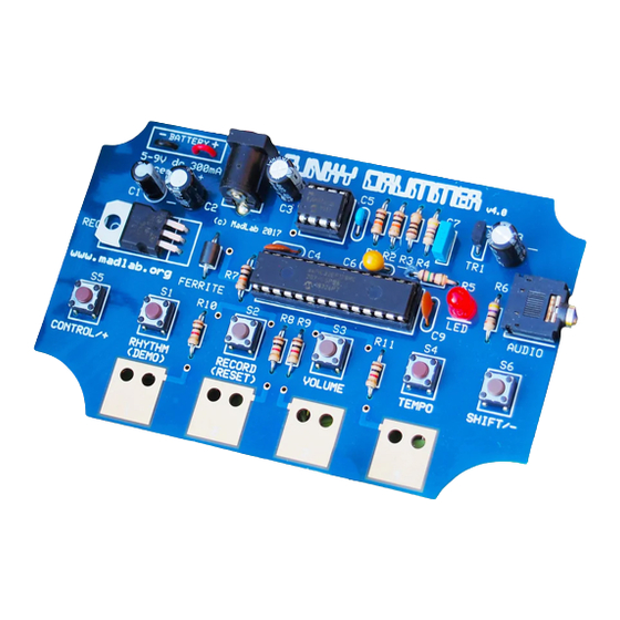
F
UNKY
programmable rhythm machine with 40 drum sounds
R1
R2
R3
R4
R5
R6
(10k)
(10k)
(100R)
(470R)
(150R)
(47R)
C1
C2
C3
C8
(10u)
(100u)
(220u)
(220u)
POWER
AUDIO
REG
(LD33V)
D
RUMMER
R7
R8
R9
R10
R11
LED
(10k)
(1k)
(1k)
(1k)
(1k)
(red)
IC1
(MCP4921)
IC1 socket
IC2
IC2 socket
(dsPIC33E)
C7
(100n)
C6
(10u)
C4
C5
C9
(100n)
(100n)
(100n)
S1
S2
S3
TR1
(ZTX689B)
S4
S5
S6
Identify the different components using the spotter chart.
1
Fit and solder all the resistors (R1 to R11) to the circuit board. Identify the
2
resistors by the coloured stripes on the body. They can be fitted either way
around.
Solder the chip sockets (IC1 and IC2) matching the notch in the socket to
3
the notch on the board. Do not solder the chips directly to the board.
Fit and solder the electrolytic capacitors (C1, C2, C3 and C8) to the board
4
putting the shorter leg into the hole with the – sign. The shorter leg also
has a stripe on the side of the body. Also solder the tantalum capacitor
(C6) so that the shorter leg is by the – sign. Fit and solder the remaining
ceramic (C4, C5 and C9) and polyester (C7) capacitors either way around.
FERRITE
Solder the ferrite bead (FERRITE) either way around.
5
Solder the light (LED) to the board putting the shorter leg into the hole
6
with the line. The shorter leg also has a flattened edge on the rim.
Solder the pushbuttons (S1 to S6) either way around.
7
Solder the transistor (TR1) matching the half-circle shape of the transistor
8
to the half-circle shape on the board.
Bend the legs of the regulator (REG) at right angles and solder it such
9
that the metal heatsink is flat on the board and the side with the writing
is facing upwards.
Solder the jack socket (AUDIO).
10
Solder the power socket (POWER). (You might find it easier to solder
11
the largest hole if you use a small piece of wire as a bridge.) Optionally
also fit the PP3 battery snap (BATTERY). Push the battery snap leads
up through the larger holes in the board from the metal side of the
board. Fit the metal tip of the red lead into the BATTERY + hole and
the metal tip of the black lead into the BATTERY – hole. Solder the
metal tips to the tracks on the board then pull the wire loops back.
Carefully bend the legs of the chips inwards a little with your fingers.
12
Fit the chips into their sockets matching the small notch in the chip to
the notch in the socket.
Attach the self-adhesive rubber feet around the edge of the board.
13
continued overleaf
Battery
snap
© MadLab® 2017
www.madlab.org
MLP114 1/9/17
Advertisement

Related Manuals for MadLab FUNKY DRUMMER

Summary of Contents for MadLab FUNKY DRUMMER
- Page 1 Fit the chips into their sockets matching the small notch in the chip to the notch in the socket. Attach the self-adhesive rubber feet around the edge of the board. POWER AUDIO (ZTX689B) continued overleaf Battery (LD33V) snap © MadLab® 2017 www.madlab.org MLP114 1/9/17...
- Page 2 Note that user rhythms are not restored though. snare #4 bass #1 bass #2 bass #3 high conga Funky Drummer can output an audio signal on its jack socket which has a low conga high bongo low bongo high agogo low agogo maximum peak-to-peak of about 2 volts.
Need help?
Do you have a question about the FUNKY DRUMMER and is the answer not in the manual?
Questions and answers