CS Instruments LD 500 Instruction Manual
Leak detector with camera
Hide thumbs
Also See for LD 500:
- Instruction manual (68 pages) ,
- Short user manual (20 pages) ,
- Short instruction manual (32 pages)

Related Manuals for CS Instruments LD 500


Summary of Contents for CS Instruments LD 500
- Page 1 EN- English Instruction manual Leak detector with camera LD 500 / LD510 LD500 V2.03 Seite 1 von 67...
-
Page 2: Table Of Contents
SSEMBLY WITH ACOUSTIC TRUMPET .......................... 10 SSEMBLY WITH FOCUS TUBE WITH FOCUS TIP ..............................11 SSEMBLY WITH OSSENECK ............................. 11 SSEMBLY WITH ARABOLIC MIRROR START-UP / / APPLICATION LD 500 ..........................12 10.1 .................................. 12 WITCH ON 10.2 ........................12 EADPHONE OLUME OLUME 10.3... -
Page 3: Table Of Content
Unique USB ID ................................. 31 11.3.4.2.9 Calibration of touchpanel ............................32 11.3.4.2.10 Set backlight brightness ............................33 11.3.4.2.11 Cleaning ................................. 34 11.3.4.2.12 System-Status ................................ 34 11.3.4.2.13 About LD 500 ................................. 34 CHARGING THE BATTERIES ............................35 LD500 V2.03 Seite 3 von 67... - Page 4 Table of Content LD 510 ..................................36 13.1 ............................36 ELECTION XTERNAL SENSOR 13.2 LD510 ..........................37 NPUT SIGNALS OF EXT SENSOR 13.3 ..............................37 ABLE CROSS SECTION 13.3.1 Sensor circuit points/Output signal: ........................ 37 13.4 ......................38 ONNECTION DIAGRAMS FOR DIFFERENT SENSOR TYPES 13.4.1 Connector pin assignment for all sensors at PI 500..................
-
Page 5: Safety Instructions
Safety instruction 2 Safety instructions About this document • Read this documentation carefully and familiarize yourself with the product before using it. Pay particular attention to the safety and warning instructions to prevent injury and product damage. • Keep this documentation handy for future reference. •... -
Page 6: Service And Maintenance
5 Intended use The LD 500 is a leak detector for quick and reliable leak detection in/on compressed air systems. The LD500 leak detector evaluates the ultrasonic waves generated by the leakage based on distance and pressure. -
Page 7: Technical Data Ld500
Technical data 6 Technical data LD500 263 x 96 x 280 mm (incl. PreAmp module and acoustic trumpet) Dimension 0,55 kg incl. PreAmp module and acoustic trumpet , Weight complete set with transportation case ca.3,5 kg Frequency range 40kHz (+/- 2kHz) Power supply Internal 7.4 V lithium-ion battery Operating time... -
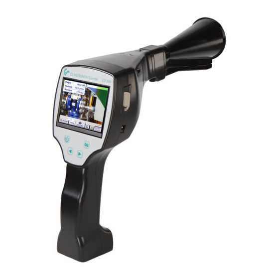
Page 8: Device Components And Controls
Device controls 8 Device components and controls The LD 500 Acoustic trumpet Unlock button for preamp module Camera Preamp module 3.5" TFT colour display with touch panel USB connection Foil keypad (4 buttons) Plug-in connection for power supply (battery On/Off button... -
Page 9: Overview And Application Description Of The Different Sensor Types
Device components and controls 9 Overview and application description of the different sensor types Acoustic trumpet (standard tool) Straightening tube The straightening tube permits only very few ultrasonic The acoustic trumpet bundles incident ultrasonic waves to pass in the direction of the ultrasonic transducer, waves, thereby extending the range of the device. -
Page 10: Assembly With Acoustic Trumpet
Device components and controls Assembly with acoustic trumpet The acoustic trumpet allows acoustic amplification by bundling the sound waves and specifies the location of the leak. Due to the special construction of the integrated laser pointer is still usable. The camera is integrated on the bottom of the acoustic trumpet and is electrically connected to the preamplifier module via the jack plug. -
Page 11: Assembly With Gosseneck
Note: To use the parabolic mirror and gooseneck, these components must be activated in the LD 500 during initial commissioning in order to save the component-specific adjustment parameters. If this has not already been done ex-works, the data for this is supplied via USB stick. For the activation (parameter import), see chapter 11 Operation here in Sub chapter "Export / Import".“. -
Page 12: Start-Up / / Application Ld 500
Commissioning 10 Start-up / / Application LD 500 Please first observe the safety instructions in Chapter 2 10.1 Switch on Hold down the power button for about 1 second, the power will turn on, and a start-up sequence will appear on the display. Pressing the button again switches the device off again. -
Page 13: Operation
Attention: Please use no pens or other objects with sharp edges! The foil can be damaged! Inputs or changes can be made with all white deposit fields 11.1 Initialization After switching on the LD 500, the initialization takes place and then switch to leakage display LD500 V2.03... -
Page 14: Screen Leckage
Operation 11.2 Screen Leckage The following picture shows and describes the display elements. Sensivity level button Displayed values for: • Signal-Level in dB • Leakage size Bar graph of Signal level • Leakage costs per year LeakTag number Actual camera image Laser „On“... -
Page 15: Home Menu Ld 500
Operation 11.3 Home menu LD 500 The operation is largely self-explanatory and menu-driven via the touch panel. The selection of the respective menu items occur via short "tapping" with the finger or a soft round pen. Attention: Please use no pens or other objects with sharp edges! The foil can be damaged! Before the leakage search is started, the device must be configured. -
Page 16: Configuration Of Ld500
Operation 11.3.1 Configuration of LD500 ➔ Home Configuration In the configuration settings the unit system can be selected and the required parameters entered, this to calculate the leakage costs per year. ➔ Selection of ISO or US unit system ➔ Call up the text field "Costs/ 1000 m³" to define the costs. There are 2 variants to choose from: •... -
Page 17: Sensortype Selection (Measuring Tool)
Operation ➔ ➔ Home Configuration Meas.Point The measuring point is stored for each leakage in its journal data. These can be seen later in the leakage report in the software. ➔ LeakTag: will be automatically increased by one after storing a measurement. All information about the measuring point can be changed by selecting the corresponding text field or the stored measuring points can be loaded from the internal database. -
Page 18: Storing Of The Measurement
Operation 11.3.1.2 Storing of the measurement To store the measurements please press either the button „Store“ on the foil keypad, see chapter Device components and controls , or by button „Store“ in the display. All data are stored on to the internal SD card. The measurement data, the measurement point and the image of the measurement point are saved as a journal, which can be exported later and a report can be created with the CS Leak Reporter (order no.: 0554 0105). -
Page 19: Fault Description
Operation 11.3.1.4 Fault description ➔ Store Textfield Fault Description In addition to the details of the measuring point with company, building and location, it is possible to enter a fault decription (up to 32 characters). To do this, select the text field „Fault description“... -
Page 20: Export/Import
Operation 11.3.2 Export/Import → With Home Export / Import, • Recorded "Leakage data" can be transferred to a USB stick • System settings can be exported as well as imported • Measuring points (company, building and location data) can be exported as well as imported. •... -
Page 21: Export
Operation 11.3.2.1 Export 11.3.2.1.1 Export „Leakage Data“ → → → Home Export / Import Export Leakage Data With the help of the „Change -button you can set a period between „Start“ and „End“. Stored measurement data that lies within this period will be exported. -
Page 22: Export Of System Settings
Operation 11.3.2.1.2 Export of System settings This feature is especially relevant to the version LD 510, here for storing the external sensor settings as well as e.g. display option for charts, sensor value etc. → → → Home Export / Import Export System settings Here the definition of the storage location... -
Page 23: Import
Operation 11.3.2.2 Import 11.3.2.2.1 Import of system settings → → → Home Export / Import Import System settings Sequence of directory and file selection is analogous to file export. Selection of internal SD card with activation of key „SdCard“ or on USB stick with key „USB“. -
Page 24: Import New Measurement Tool
Operation 11.3.2.2.2 Import new measurement tool → → → Home Export / Import Import Import new Tool The directory and file selection process is the same as for export e.g. system settings Selection of internal SD card with activation of button "SdCard" or of USB stick withbutton "USB". -
Page 25: Export / Import Customer Database
These functions allow the stored measuring point descriptions (companies, buildings and location) to be exported as an XML file or to be imported from another LD 500 exported database. That means it is also possible to create and import the database externally, but the prerequisite is the correct format of the XML file. -
Page 26: View Bitmaps
Operation 11.3.3 View bitmaps → → Home View Bitmaps Select Screenshoot This allows the stored pictures (measurement pictures) on the SD-Card or USB Stick to load and shown in the display again. Please press button „Select Screenshot“ and select the required picture (bitmap). The pictures are stored and organized in different directories The directory structure is year / calendar week... -
Page 27: Device Settings
Settings 11.3.4 Device Settings The settings are all protected by a password! Settings or changes are generally confirmed with OK! Remark: If you go back to main menu and then again one of the setting menus is called, you must enter the password again. -
Page 28: Device Settings
11.3.4.2 Device Settings Home ➔Settings ➔ Device settings Overview of Device settings 11.3.4.2.1 Language Home ➔Settings ➔ Device settings ➔ Set language Here you can select one of 11 languages for the LD 500. LD500 V2.03 Seite 28 von 67... -
Page 29: Date & Time
Settings 11.3.4.2.2 Date & Time Home ➔Settings ➔ Device settings ➔ Date & Time By pushing the Time Zone description field and enter the correct UTC, you can set the correct time all over the world. The summer and wintertime switchover is realized by pushing the Daylight Saving button. -
Page 30: System Update
Settings 11.3.4.2.4 System update If required, there is the possibility for the LD 500 to download a firmware update to the device via the USB stick. The latest software is available on the CS Instruments GmbH homepage The received file must then be stored on the USB stick and transferred to your device as described below. -
Page 31: Update Channels
Bevor the settings are changed to the production default settings a safety prompt is displayed and must be confirmed by pressing the button „Yes“. If needed with „Reboot System“ the LD 500 could be started(reboot) here. 11.3.4.2.8 Unique USB ID For connections with the PC, a status and therefore a unique USB ID can be defined here. -
Page 32: Calibration Of Touchpanel
Settings 11.3.4.2.9 Calibration of touchpanel Home ➔Settings ➔ Device settings ➔ calibrate touchscreen If necessary, the touch-screen calibration can be changed here. Push Calibrate and it appears, 1. left above,2. bottom right, 3. bottom left, 4.right above and 5. in the middle, a calibration cross that must be pushed consecutively. -
Page 33: Set Backlight Brightness
Settings 11.3.4.2.10 Set backlight brightness Home ➔Settings ➔ Set backlight Here you adjust the desired Backlight (15-100%) of the display directly. E.g. Backlight to 39 % With the help of the Backlight dimming after button, after a definable time interval (here after 15 minutes), the Backlight can be... -
Page 34: Cleaning
11,74 V 11,74 V voltages and an operating hour counter. 5.01 V 5.01 V 11.3.4.2.13 About LD 500 Home ➔ Settings ➔ about LD 500 *** About LD 500 *** Device Brief description of the Hardware Software Version, as well as the... -
Page 35: Charging The Batteries
The LD 500 checks the charging status of the battery and starts the charging process automatically if necessary. To protect the Li-ION accumulator of exhaustive discharge the device is switching off automatically if a cell voltage of 6,4V will be reached. -
Page 36: Ld510
LD510 13 LD 510 13.1 Selection External sensor The use of an „external Sensor“ requires to switch to its mode. Home ➔ Mode ➔ Externer Sensor Home menu for external sensor connection LD500 V2.03 Seite 36 von 67... -
Page 37: Input Signals Of Ext
Input Signals ext. sensor 13.2 Input signals of ext. sensor LD510 Input signals Measuring range 0 – 20 mA / 4 – 20 mA Current signal Resolution 0,0001 mA (0 – 20 mA / 4 – 20 mA) internal or external ... -
Page 38: Connection Diagrams For Different Sensor Types
Connection diagrams 13.4 Connection diagrams for different sensor types 13.4.1 Connector pin assignment for all sensors at PI 500 The interface connector to be used is a ODU Medi Snap 8 pin – Reference: K11M07-P08LFD0-6550 Available connection cables at CS-Instruments are: ODU with Open ends: Order no 0553 0501, cable length: 5 m. -
Page 39: Connection For Cs Dew Point- And Consumption Sensors, Series Fa/Va 5Xx
Connection diagrams 13.4.2 Connection for CS dew point- and consumption sensors, series FA/VA 5xx + RS485 Weiss / White LD 510 - RS485 Braun / Brown FA 5xx VA 5xx Analog IN + VD 500 Sensor Analog IN - I (500µA) The digital data transmission between LD 510 and the Blau / Blue +VB 24Vdc... -
Page 40: Analogue Two-, Three-, And Four-Wire Current Signal
Connection diagrams 13.4.5 Analogue two-, three-, and four-wire current signal Sensors with 4 - 20 mA-output in 2-wire technology + RS485 - RS485 ß 0 / 4 ...20mA Analog IN + LD 510 Yellow Analog IN - Sensor I (500µA) +VB 24Vdc blue -VB GND... -
Page 41: Two-, Three- And Four-Wire Connector Pin Assignments For Pt100/Pt1000/Kty81
Connection diagrams 13.4.6 Two-, three- and four-wire connector pin assignments for PT100/PT1000/KTY81 + RS485 - RS485 Yellow Analog IN + 2-wire PT100/PT1000/KTY81 Analog IN - I (500µA) pink +VB 24Vdc -VB GND + RS485 - RS485 Yellow Analog IN + 3-wire PT100/PT1000/KTY81 Analog IN - grey... -
Page 42: Dew Point Sensor Fa 500 / Fa 510 (Rs 485 Modbus)
Dew point Sensor FA5xx 13.5 Dew Point Sensor FA 500 / FA 510 (RS 485 Modbus) First step: choose an unused sensor digital channel External sensor ➔ Settings ➔ Sensor settings ➔ C1 Second step: choose type FA 5xx External sensor➔Settings➔ Sensor settings ➔ C1 ➔ description field ➔ Dew Point →FA 5xx Now the Type FA 5xx is to be selected for... -
Page 43: Settings Dew Point Sensor Fa 500 / Fa 510
Dew point sensor FA5xx 13.5.1 Settings Dew point sensor FA 500 / FA 510 13.5.1.1 Unit selection for temperature and humidity External sensor ➔ Settings ➔ Sensor settings ➔ C1➔ arrow right (2.page) Unit selection for temperature and humidity by pressing the button °C, °F, g/m³... -
Page 44: Definition Of Reference Pressure (Absolute Pressure Value)
Dew point sensor FA5xx 13.5.1.3 Definition of Reference pressure (absolute pressure value) External sensor ➔ Settings ➔ Sensor settings ➔ C1➔ arrow right (2.page)➔Pressure Setting ➔ Text field Ref.Pressure Reference pressure is the pressure for that the dew point in relaxation will be back- calculated. -
Page 45: More Settings Analogue Output 4-20Ma
Dew point sensor FA5xx 13.5.1.5 More Settings Analogue output 4-20mA External sensor ➔ Settings ➔ Sensor settings ➔ C1➔ arrow right (2.page)➔ More-Settings ➔ 4-20mA This menu allows the adjustment / assignment of the measurement value and the scaling of the analogue output. -
Page 46: Flow Sensor Of Type Va 500 / Va 520 / Va 550 / Va 570 (Rs 485 Modbus)
Flow sensor VA5xx 13.6 Flow sensor of type VA 500 / VA 520 / VA 550 / VA 570 (RS 485 Modbus) First step: choose an unused sensor digital channel External sensor ➔ Settings ➔ Sensor settings ➔ C1 Second step: choose type VA 5xx External sensor ➔... -
Page 47: Settings For Flow Sensor Va 5Xx
Flow sensor VA5xx 13.6.1 Settings for Flow sensor VA 5xx External senor ➔ Settings ➔ Sensor settings ➔ C1➔ arrow right (2.page) For each text field could be the either a value or a unit be set. Settings by entering the text field and then input a value or select the unit for the appropriate field. -
Page 48: Gas Constant Settings
Flow sensor VA5xx 13.6.1.2 Gas Constant settings ➔ Settings ➔ Sensor settings ➔ C1➔ arrow right (2.page) ➔ Gas Constant description field External senor All gases marked in blue and with (real) have been a real gas calibration curve stored in the sensor. Select the gas you require and confirm selection by pressing button. -
Page 49: Definition Of The Reference Conditions
Flow sensor VA5xx 13.6.1.3 Definition of the reference conditions Here, the desired measured media reference conditions for pressure and temperature can be defined ➔ Settings ➔ Sensor settings ➔ C1➔ arrow right (2.page) ➔ Ref. Pressure description field External senor ➔... -
Page 50: Definition Consumption Counter Value And Consumption Unit
Flow sensor VA5xx 13.6.1.5 Definition consumption counter value and consumption unit ➔ Settings ➔ Sensor settings ➔ C1➔ arrow right (2.page) ➔ Count Val. description Field External senor ➔ Settings ➔ Sensor settings ➔ C1➔ arrow right (2.page) ➔ Count Val. Unit description Field External senor The sensor allows taking over a starting counter value. -
Page 51: Settings Analogue Output 4-20Ma Of Va 5Xx
Flow sensor VA5xx 13.6.1.6 Settings analogue output 4-20mA of VA 5xx ➔ Settings ➔ Sensor settings ➔ C1➔ ➔ arrow right (2.page) → More-Settings ➔ 4-20mA Ch1 External senor This menu allows the adjustment / assignment of the measurement value and the scaling of the analogue output by pressing the”4-20mA Ch1”... -
Page 52: Settings Pulse / Alarm Output Of Va 5Xx
Flow sensor VA5xx 13.6.1.7 Settings Pulse / Alarm output of VA 5xx ➔ Settings ➔ Sensor settings ➔ C1➔ arrow right (2.page) → More-Settings ➔ Pulse / Alarm External senor The pulse output of the VA 5xx could be set functionally as pulse output or alarm output. - Page 53 Flow sensor VA5xx ➔ Settings ➔ Sensor settings ➔ C1➔ arrow right (2.page) → More-Settings ➔ Alarm External senor In case of use the pulse output as alarm following definitions needs to be set: Unit selection by pressing “unit” button and choice one of the possible units “cfm”, “ltr/s”,...
-
Page 54: Settings Zeropoint Or Low Flow Cut Off For Va 5Xx
Flow sensor VA5xx 13.6.1.8 Settings ZeroPoint or Low Flow Cut off for VA 5xx Settings ➔ Sensor settings ➔ C1 ➔ More-Settings ➔ Zeropoint ➔ arrow right (2.page) → External senor With these function following adjustments could be done. 2.045 Zeropoint: When, without flow, the installed sensor shows already a flow value of >... -
Page 55: Type Modbus
Sensor Type Modbus 13.7 Type Modbus 13.7.1 Selection and activation of Sensor-Type Modbus First Step: First step: choose an unused sensor channel External sensor ➔ Settings ➔ Sensor settings ➔ C1 Second step: choose type Modbus External sensor ➔ Settings ➔ Sensor settings ➔ C1 ➔ Type description field ➔ Modbus Third step: confirm with OK. - Page 56 Sensor Type Modbus External sensor ➔ Settings ➔ Sensor settings ➔ C1 ➔ Reg. Address description field The measurement values are kept in the registers of the sensor and can be addressed via Modbus and read by the PI 500 This requires setting the desired register addresses in the LD 510 Entering the register / data address is...
- Page 57 Sensor Type Modbus Example: Holding Register - UI1(8b) - Value: 18 Selection Register Type Holding Register, Data Type U1(8b) und Byte Order A / B HByte LByte 18 => Data Order 1. Byte 2. Byte Holding Register – UI4(32) - Value: 29235175522 → AE41 5652 Selection Register Type Holding Register,...
- Page 58 Sensor Type Modbus External sensor ➔ Settings ➔ Sensor settings ➔ C1 ➔ Scale- description field The use of this factor allows adapting the output value by the same. By default or value = 0 no scaling is applied and displayed in the field is don’t scale External sensor ➔...
-
Page 59: Data Logger Settings
Datalogger 13.8 Data logger Settings External sensor ➔ Settings ➔ Logger settings In the top row you can select the predefined Time intervals 1, 2, 5, 10, 15, 30, 60 and 120 seconds for recording. A different, individual Time interval be entered in the highlighted white description field right at the head, where the currently set... - Page 60 Datalogger External sensor ➔ Settings ➔ Logger settings ➔ force new Record File button External sensor ➔ Settings ➔ Logger settings ➔ force new Record File button ➔ Comment description field A new recording file will be created by pushing the force new record file button and a name or comment can be entered...
- Page 61 Datalogger External senor ➔ Settings ➔ Logger settings ➔ timed Stop button By pushing the timed Stop button and then the date/time description field below, the date and the stop time can be set for a data logger recording. Remark: If the stop time activated, it will automatically be set to the current time plus an hour.
- Page 62 Datalogger External senor ➔ Settings ➔ Logger settings ➔ timed Start button/timed Stop button ➔ Date/Time description field ➔ Cal button With the button the desired date can be easily select from the calendar. External senor ➔ Settings ➔ Logger settings ➔ Start button After the start and stop time activation and the created settings, Start...
-
Page 63: Scope Of Delivery
Appendix 14 Scope of delivery LD 500 is available either as a single unit or in a set. The set contains all the components and accessories that are protected in a rugged and shock-resistant transport case. Transport case (0554 0106) - Page 64 Appendix Diese Erklärung beinhaltet keine Zusicherung von Eigenschaften. Die Sicherheitshinweise der mitgelieferten Produktdokumentation sind zu beachten. LD500 V2.03 Seite 64 von 67...
- Page 65 Appendix LD500 V2.03 Seite 65 von 67...
- Page 66 Appendix LD500 V2.03 Seite 66 von 67...
- Page 67 Contact SALES OFFICE NORD Gewerbehof 14 D-24955 Harrislee DEUTSCHLAND Tel.: +49 (0) 461 80 71 50 - 0 Fax: +49 (0) 461 80 71 50 - 15 info@cs-instruments.com www.cs-instruments.de SALES OFFICE SOUTH Zindelsteiner Straße 15 D-78052 VS-Tannheim DEUTSCHLAND Tel.: +49 (0) 7705 978 99-0 Fax: +49 (0) 7705 978 99-20 info@cs-instruments.com www.cs-instruments.de...
Need help?
Do you have a question about the LD 500 and is the answer not in the manual?
Questions and answers