Tormach PCNC 440 Operator's Manual
Hide thumbs
Also See for PCNC 440:
- Technical document (29 pages) ,
- Installation manual (21 pages) ,
- Owner's manual (14 pages)
Table of Contents
Advertisement
Quick Links
TORMACH
PCNC 440
®
™
OPERATOR'S MANUAL
IMPORTANT! Read and understand all operator's manual safety precautions and instructions before at-
tempting PCNC 440 installation, operation, or maintenance.
Questions or comments?
UM10372_PCNC440_Manual_0221A
Please email us: info@tormach.com
Document Part Number: 35672
All rights reserved.
©2021 Tormach Inc.
Advertisement
Table of Contents

Related Manuals for Tormach PCNC 440


Summary of Contents for Tormach PCNC 440
- Page 1 PCNC 440 ® ™ OPERATOR’S MANUAL IMPORTANT! Read and understand all operator’s manual safety precautions and instructions before at- tempting PCNC 440 installation, operation, or maintenance. Questions or comments? UM10372_PCNC440_Manual_0221A Please email us: info@tormach.com Document Part Number: 35672 All rights reserved.
- Page 2 This manual contains important safety warnings and operating instructions for the PCNC 440 mill. Refer to these instructions before attempting installation, operation or maintenance. Keep these instructions together with your PCNC 440 mill so they are readily accessible. The most recent version of this manual is available at: www.tormach.com/documents Read Before Operating Read and follow all warnings, cautions, and operating instructions before operating this machine.
- Page 3 PREFACE Machine Safety Safe operation of the machine depends on its proper use and the precautions taken by the operator. Read and understand this manual. Only trained personnel – with a clear and thorough understanding of its operation and safety requirements – should operate this machine. General Safety: •...
- Page 4 Failure to do so could result in death and/or serious injury. Input Power: The PCNC 440 has one 115 V power input which is capable of delivering lethal electrical shocks. Care should be exercised when working inside the electrical cabinet.
- Page 5 The right to make copies of this manual is granted solely for the purpose of training courses related to, evaluation of and/or use of the PCNC 440. It is not permitted, under this right, for third parties to charge for copies beyond the cost of printing.
- Page 6 Feed Rate Range 0-110 IPM (Z) The PCNC 440 is capable of cutting any material that can be cut with a rotating cutter at or near its recommended feeds and speeds. As with any machine tool, care should be exercised so that programmed cuts do not exceed the maximum available spindle horsepower.
- Page 7 PREFACE Each PCNC 440 ships with a Certificate of Inspection. This report details each of the quality assurance measurements performed at the factory by a Tormach quality assurance team member prior to approving shipment of each machine. A sample certificate of inspection and more information on quality assurance measurements is available at: http://www.tormach.com/quality_overview.html...
-
Page 8: Table Of Contents
3.1.1 Shipment Arrival 3.1.2 Moving the Crate 3.1.3 Initial Uncrating 3.1.4 Shipping Damage or Shortages 3.2 Installation Sequence 3.3 Basic Installation Procedure 3.3.1 Stand Assembly 3.3.2 Remove Pallet Items 3.3.3 Lift and Move Mill 3.3.3.1 Remove Mill from Pallet 3.3.3.2 Lift Mill 3.3.4 Attach Mill to Stand 3.3.4.1 Non-Tormach Stands Chapter 1 UM10372_PCNC440_Manual_0221A... - Page 9 PREFACE 3.3.5 X-axis Motor Cover Plate 3.3.6 X-axis Limit Switch Cover Plate 3.3.7 Manual Oiler 3.3.8 Flood Coolant System 3.3.9 Install the Monitor 3.3.10 Install the PathPilot Controller 3.4 Essential Controls Overview 3.4.1 E-stop, Start, Reset, and Main Disconnect 3.5 Power Off/Power On Procedure 3.6 Initial PathPilot Controller Configuration 3.7 Validate Basic Installation 3.7.1 Verify Limit Switch Function 3.7.2 Verify Axis Function 3.7.3 Verify Spindle Function...
- Page 10 PREFACE 4.4.1 Spindle Control Via PathPilot Interface 4.4.2 Changing Spindle Speed Range 4.5 Tool Holders 4.5.1 Install Drawbar and TTS Collet 4.5.2 Change TTS Tool Holder 4.5.3 Tips on Using TTS 4.6 Part Setup/Workholding 5. Intro to PathPilot 5.1 Making Your First Part 5.1.1 Reference the Mill 5.1.2 Prepare the Workpiece 5.1.3 Prepare the Tools 5.1.4 Understand Mill Position, Work Offsets and Tool Offsets 5.1.5 Set the Length Units...
- Page 11 PREFACE 6.3 Keyboard Shortcuts 6.4 Main Tab 6.4.1 Selecting a Recent G-code Program File 6.4.2 Working in the G-code Window 6.4.2.1 Setting a New Start Line 6.4.2.2 Expanding the G-code Window 6.4.3 Manually Entering Commands 6.4.3.1 Searching in the Code 6.4.4 Working in the Tool Path Window 6.4.4.1 Changing the View of the Tool Path Window 6.5 File Tab 6.5.1 Managing Files 6.5.1.1 Transferring Files or Folders from a USB Drive...
- Page 12 PREFACE 6.7 Offsets Tab 6.7.1 Tool Tab 6.7.1.1 Tool Measuring Techniques 6.7.1.2 Creating Tool Descriptions 6.7.2 Offsets Table 6.7.3 Tool Offset and Fixture Information Backup 6.7.4 Work Tab 6.8 Conversational Tab 6.8.1 Using Feeds and Speeds Suggestions 6.8.1.1 Adjusting DRO Values 6.8.1.2 Resetting DRO Values 6.8.1.3 Using Chip Load Information 6.8.2 Face Tab 6.8.3 Profile Tab 6.8.4 Pocket Tab 6.8.4.1 Rectangular...
- Page 13 PREFACE 6.10 ADMIN Commands 7. Programming 7.1 Definitions 7.2 G-code Programming Language 7.2.1 Overview 7.2.2 Block 7.2.3 Real Value 7.2.4 Number 7.2.5 Formatting G-code Blocks 7.2.6 Optional Program Stop Control – (M01 BREAK) 7.2.7 Additional G-code Formatting Notes 7.2.7.1 Repeated Items 7.2.7.2 Order of Execution 7.2.7.3 Error Handling 7.2.7.4 Modality and Modal Commands 7.2.7.5 Modal Groups 7.2.7.6 Default Modes 7.3 G-codes 7.3.1 Rapid Linear Motion –...
- Page 14 PREFACE 7.3.5.3 Set Tool Table – G10 L10 7.3.5.4 Set Tool Table – G10 L11 7.3.5.5 Set Coordinate System – G10 L20 7.3.6 Plane Selection – G17, G18, and G19 7.3.7 Length Units – G20, G21 7.3.8 Return to Pre-defined Position – G28, G28.1 7.3.9 Return to Pre-defined Position – G30, G30.1 7.3.10 Straight Probe –...
- Page 15 PREFACE 7.4.2 Cancel Active Canned Cycle – G80 7.4.3 Simple Drilling Cycle – G81 7.4.4 Simple Drilling Cycle (dwell) – G82 7.4.5 Peck Drilling Cycle – G83 7.4.6 Boring Cycle (feedrate out) – G85 7.4.7 Boring Cycle (dwell, rapid out) – G86 7.4.8 Boring Cycle (dwell, manual out) – G88 7.4.9 Boring Cycle (dwell, feedrate out) –...
- Page 16 PREFACE 7.7.2.2 Subroutine Parameters 7.7.2.3 Named Parameters 7.7.3 Expressions 7.7.3.1 Binary Operators 7.7.3.2 Functions 7.8 Programming with Subroutines 7.8.1 Subroutine Labels and Subroutine Keywords 7.8.1.1 Defining a Subroutine 7.8.1.2 Calling a Subroutine 7.8.1.3 Conditional Subroutines 7.8.1.4 Repeating Subroutines 7.8.1.5 Looping Subroutines 8. Accessories 8.1 Stands and Enclosures 8.1.1 Full Enclosure Kit 8.1.2 Stand 8.2 Coolant System Options 8.2.1 Flood Coolant Kit 8.2.2 Spray Coolant 8.2.3 Coolant Hose and Accessories...
- Page 17 PREFACE 8.3.5.1 Calibrating Probe Tip 8.3.5.2 Measuring Probe Tip Diameter 9. Maintenance 9.1 Regular Maintenance 9.1.1 Rust Prevention 9.1.2 Way Covers 9.1.3 Flood Coolant System 9.1.4 Lubrication System 9.1.4.1 Manual Oiler Specifics 9.1.5 Drawbar and TTS Collet 9.2 Spindle Belt 9.3 Advanced Maintenance 9.3.1 Overview 9.3.2 Definitions 9.3.2.1 How to Measure Lost Motion 9.3.3 Gib Adjustment 9.3.3.1 Overview 9.3.3.2 Adjustment Procedure 9.3.4 Angular Contact Bearing Preload Adjustment...
- Page 18 PREFACE 10.3 X-Y Axis Assembly (exploded view) 10.4 Electrical Cabinet 10.5 Connections 10.6 Stepper Connections 10.7 Lubrication System 11. Electrical Schematics 11.1 PCNC 440 Electrical Schematic 11.2 PCNC 440 4th Axis Wiring Chapter 1 UM10372_PCNC440_Manual_0221A...
-
Page 19: Overview
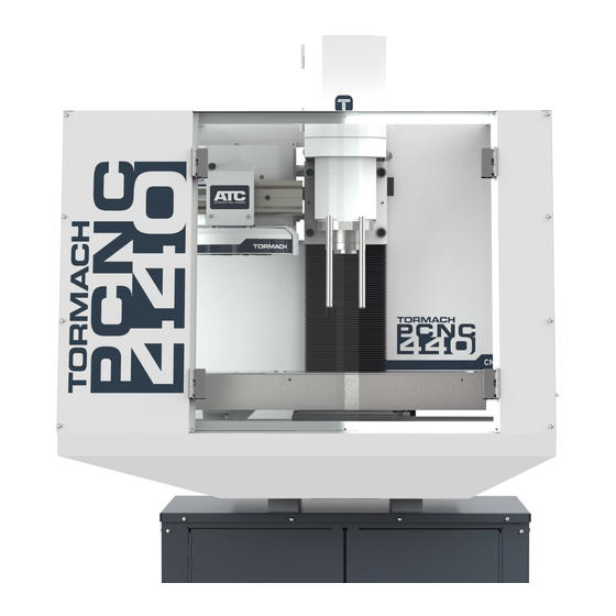
OvERviEw 1. OvERviEw Tormach PCNC mills are intended for use as general purpose CNC mills. Pictured below is a typical PCNC 440 mill set up, including several options. Figure 1.1 Item # Component Item # Component Electrical Cabinet Spindle Door... -
Page 20: Specifications
OvERviEw 1.1 Specifications Mechanical Length 18” Width 6.25” T-Slot Width 10 mm T-Slot Center-to-Center Distance 50 mm Dimensions Number of Standard T-Slots Three along X-axis (machine table) Maximum Weight on Table 150 lbs. Spindle Nose to Table (~max) 12” Spindle Nose to Table (~min) 2”... -
Page 21: Site Planning And Prep
SiTE PlANNiNg ANd PREP 2. SiTE PlANNiNg ANd PREP This section covers required site preparations prior to placing PCNC mill in service. 2.1 General Site Requirements The area should be well lit, dry, have proper ventilation, provide for unobstructed machine motion/operation, and ensure unrestricted access to PCNC mill controls. -
Page 22: Electrical Requirements
(water pipe or similar) to ensure proper grounding. 2.2.2 Plug Pattern The PCNC 440 is shipped with a 3-prong plug. This plug is designed to be used with a 3-prong outlet. 2.2.3 Ground Fault Interrupter (GFI) Use Primary power for the PCNC 440 should not be protected by a ground fault interrupter (GFI), as this interferes with the proper operation of the PCNC mill’s spindle controller. -
Page 23: Electrical Noise
Consult with an electrician to determine suitability for the specific site. • Step-up/Step-down Transformer (PN 32009): used to reduce 230 VAC line voltage to 115 VAC, as required by the PCNC 440; commonly used for PCNC 440 mills located outside of the USA and Canada. -
Page 24: Installation
3. iNSTAllATiON This chapter covers basic installation of a PCNC 440 mill, which takes approximately two hours. This estimate does not include optional accessories like enclosures, power drawbars, or automatic tool changers (ATC). Required for set up: • Power Strip Recommended for installation/set up: •... -
Page 25: Initial Uncrating
3.3 Basic Installation Procedure Follow the steps in this section to complete basic mill installation. 3.3.1 Stand Assembly If purchased, the PCNC 440 Stand (PN 35671) should be assembled first. Refer to documentation that ships with the stand for information on assembly. UM10372_PCNC440_Manual_0221A... -
Page 26: Remove Pallet Items
iNSTAllATiON 3.3.2 Remove Pallet Items X-axis Limit 1. Carefully cut straps to remove plastic Switch Cover Plate Tool Box strapped to pallet (see Figure 3.2); set aside for use later. This box contains tools required for installation. NOTE: The mill’s drawbar is located in the Tool Box. -
Page 27: Attach Mill To Stand
3. Using four M12 x 100 mm studs, washers, and nuts, attach chip pan, mill, and stand Stand together; tighten nuts securely. 3.3.4.1 Non-Tormach Stands Figure 3.5 If an alternative stand is used, ensure: • Stand has a minimum weight capacity of... -
Page 28: Install The Monitor
iNSTAllATiON 3.3.9 Install the Monitor The PathPilot controller mount allows you to install the PathPilot controller behind the monitor (which is attached to the Controller Arm). Note: If you’re using a Touch Screen Kit (PN 35575), you must first remove the stock mounting bracket from the back of the monitor. - Page 29 iNSTAllATiON 3. Attach the 4-port USB hub (provided in the machine owner’s kit) below the Brix PathPilot Controller with double-sided tape (provided with the controller mount). 4. Connect the USB hub’s cord to any open USB port on the Brix PathPilot Controller.
-
Page 30: Essential Controls Overview
iNSTAllATiON 3.4 Essential Controls Overview Check to ensure your local power supply meets the requirements detailed in chapter 2, Site Planning and Prep. 3.4.1 E-stop, Start, Reset, and Main Disconnect NOTE: Before continuing, review Power Off/On Operator Box Procedure later in this chapter. E-stop (emergency stop) The mill has one emergency stop button or E-stop pre-installed on the... -
Page 31: Power Off/Power On Procedure
iNSTAllATiON Main Disconnect The Main Disconnect switch, located on the right side of the electrical cabinet, is used to power the mill on and off (see Figure 3.15). When the Main Disconnect is switched to power Off, this disconnects the primary supply power to the mill. 3.5 Power Off/Power On Procedure IMPORTANT! Do not power on motors and drives via the green Start button before powering on the controller that oversees their operation. -
Page 32: Initial Pathpilot Controller Configuration
The first time the PathPilot controller is powered on it starts a configuration process that allows the operator to configure the PathPilot operating system to the particular machine (PCNC 1100 mill, PCNC 770 mill, PCNC 440 mill, or 15L Slant-PRO lathe). Follow the on-screen instructions to complete controller configuration. After configuration, PathPilot automatically launches; the controller automatically loads PathPilot for the selected machine when the controller is powered on in the future. -
Page 33: Validate Basic Installation
iNSTAllATiON 3.7 Validate Basic Installation Validate basic setup before you install any accessory kits. IMPORTANT! Follow Power Off/On Procedure detailed earlier in this chapter. After powering on, jog the Z-axis up to remove the shipping block between the spindle nose and the machine table. -
Page 34: Verify Axis Function
iNSTAllATiON 3.7.2 Verify Axis Function 1. Reference the mill by clicking the Ref Z, Ref X, and Ref Y buttons (see Figure 3.19); the mill moves. 2. Next, switch to the Main screen. 3. Use keyboard to verify axis motion: a. -
Page 35: Controller Customization
iNSTAllATiON 3.8 Controller Customization Date and Time To set or edit controller’s date and time, type ADMIN DATE in the MDI field and click Enter on keyboard (see Figure 3.21). This opens a dialog box to enter or edit date, time, and time zone. Click Close when finished. -
Page 36: Operation
OPERATiON 4. OPERATiON This chapter provides an overview of the basic controls of the PCNC 440 mill. WARNING! Unattended Operation: Machine is not designed to operate unattended. Do not leave machine unattended during operation. When machine is not in use, turn the main disconnect off. Failure to do so could result in death, serious injury, and/or machine damage. -
Page 37: Accessory Port
OPERATiON 4.1.3 Accessory Port Accessory The Accessory Port is located on the side of the Port electrical panel (see Figure 4.2). 4.2 Initializing the Mill To prepare the mill for motion, the mill must be initialized. 4.2.1 Vital Reference After powering on, the mill must be referenced in the X-, Y-, and Z-axes. -
Page 38: Jog Shuttle
OPERATiON Jog Shuttle Wheel Shuttle Ring Figure 4.5 Figure 4.4 4.3.2 Jog Shuttle The Jog Shuttle (PN 30616) is an optional accessory (see Figure 4.4) that many operators find increases productivity, especially on short-run jobs requiring extensive setting up of the workpiece and tooling. - Page 39 To specify spindle RPMs, click the DRO. Using the keyboard, type the desired RPM and press Enter. • Click FWD to run the spindle clockwise • Click Stop to stop the spindle 4.4.2 Changing Spindle Speed Range The PCNC 440 mill has two speed ranges: High 300-4500 650-10,000 The range change is performed by moving the spindle belt from the top pair of pulleys (high speed range) to the lower pair of pulleys (low speed range).
- Page 40 • Quickest manual tool change time • Shortest tool change clearance distance • Compatibility with Tormach power drawbar and Tormach automatic tool changer (ATC) TTS uses a precision 3/4” collet in combination with a drawbar and interchangeable TTS tool holders.
- Page 41 R8 collets and R8 taper tool holders are also compatible. These are installed in a similar manner to the TTS collet as described above, but must be removed completely during each tool change. NOTE: The PCNC 440 ships with a drawbar with 7/16”-20 UNF thread. UM10372_PCNC440_Manual_0221A...
- Page 42 OPERATiON 4.6 Part Setup/Workholding Work must be secured to the table prior to machining. Each PCNC 440 has three 10 mm T-slots that run parallel to the X-axis. The slots are precision ground to +0.008”. A 4” vise is recommended. Tormach offers the following vise:...
- Page 43 5. iNTRO TO PATHPilOT 5.1 Making Your First Part This chapter outlines how to make your first part on a Tormach mill. It assumes you have no prior experience running a part program on a CNC mill. Even if you have previous CNC experience, following this tutorial gives you an introduction to the controls of the mill.
- Page 44 1/8” or smaller diameter end mill to engrave the text (see Figure 5.3). You will also need a way to hold these tools. Tormach’s High Tool 2 Speed Steel End Mill Kit (PN 33465) includes both end mills.
- Page 45 iNTRO TO PATHPilOT Tool Offsets Tool offsets allow the operator to use tools of different length and, in the case of cutter radius compensation, different diameters. In the program you will create during this tutorial, you will use two different tools. Because it is extremely unlikely that these tools will be exactly the same length, the control needs to account for the difference in tool length when switching tools.
- Page 46 iNTRO TO PATHPilOT 5.1.6 Touch Off the Workpiece to Set Work Offsets There are many ways of conceptualizing tool and work offsets, but we use the idea of a true positive tool length to demonstrate this first part program. When using this method we will touch the face of the spindle to the top of the workpiece to set the work Z zero (see Figure 5.4).
- Page 47 iNTRO TO PATHPilOT 5. Click the Zero Z button next to the Z DRO to set the work offset Z to zero. NOTE: This is just like typing 0.0 into the Z DRO and pressing Enter. To account for the thickness of the paper used in touching off the work offset, you could type 0.003 in the Z DRO and press Enter.
- Page 48 iNTRO TO PATHPilOT 3. On the Offsets tab, enter 0.0 in the touch DRO and click the Touch Z button (see Figure 5.8). If you were not touching on the top of the workpiece, but instead using a feeler gauge or piece of paper between the workpiece and the tool, you could enter the thickness of the gauge or paper in the touch...
- Page 49 iNTRO TO PATHPilOT 5.1.8.1 Operation 1 To write the code for the first operation, click the Conversational tab (see Figure 5.10). The Conversational screen is divided into two sections: parameters common to most operations are displayed on the left and parameters (including part geometry) that are operation specific are displayed on the right.
- Page 50 iNTRO TO PATHPilOT 1. Grab the Maxvel slider (lower left hand corner of screen) by clicking and dragging it down to zero (see Figure 5.12). NOTE: If your mill is equipped with an ATC, setting Maxvel to zero stops all motion and will prevent the mill from changing tools.
- Page 51 iNTRO TO PATHPilOT 3. Grab Maxvel slider again and slowly increase allowed velocity (see Figure 5.12). Bring velocity back down to zero when you get close to the part and double check values in the DROs to make sure that tool position looks correct. For example, if tool is 1/4” above the workpiece, Z DRO should read 0.2500.
- Page 52 iNTRO TO PATHPilOT Figure 5.15 Figure 5.14 3. Click on the name of the file you created when you made the facing G-code, then click Append to File (see Figure 5.14). The changes to your file are loaded into the control, and you should see a tool path that looks something like Figure 5.15.
- Page 53 PATHPilOT iNTERFACE 6. PATHPilOT iNTERFACE 6.1 Overall Layout The PathPilot® interface is divided into two sections: Notebook and Persistent Controls (see Figure 6.1). Persistent Controls make up the bottom half of the screen with three control groups: Program Control Group, Position Status Group, and Manual Control Group. The top half of the screen is the Notebook, which includes seven tabs: Main, File, Settings, Offsets, Conversational, Probe, and Status.
- Page 54 Persistent Controls half of the PathPilot interface contains the controls used to set up a job and execute G-code. Operators already familiar with Tormach milling machines (or most other CNC machines) will be familiar with many of the Persistent Controls buttons.
- Page 55 PATHPilOT iNTERFACE Single Block – Turns Single Block on (LED illuminated) or off. When Single Block mode is active, the mill executes one block of G-code, then pauses and flashes the Cycle Start button LED, indicating that Cycle Start needs to be clicked to execute the next line of G-code. This feature may be turned on or off before running a program or during program execution.
- Page 56 PATHPilOT iNTERFACE Spindle Override – The Spindle Override Slider and RPM 100% button allow you to override the commanded spindle speed by percentages ranging from 1 percent to 150 percent. The RPM 100% button returns the override to 100 percent of the commanded value or no override. The spindle must be running for these controls to have a noticeable effect.
- Page 57 PATHPilOT iNTERFACE This technique is used for setting any DRO. Remember to click Enter after any DRO change. If you forget and just click on another DRO field, any value you have just entered is discarded. This is designed to avoid accidental changes. For convenience, the Zero button to the left of the axis DROs can be used to set the current work offset position for that axis to 0.000.
- Page 58 PATHPilOT iNTERFACE Jog Shuttle Jogging with Keyboard Keys Shuttle Ring A-Axis Motion Wheel X-Axis Motion Figure 6.5 Figure 6.6 Jogging Controls – The mill can be jogged with either the optional Jog Shuttle shown in Figure 6.5 or with the keyboard (see Figure 6.6): •...
- Page 59 PATHPilOT iNTERFACE Step Size Buttons Spindle Jog Speed Jog Cont/ Slider Step Figure 6.7 Figure 6.8 Step and Continuous Jogging – Whether using the jog shuttle or the keyboard, there are two modes of jogging: continuous and step. When using the keyboard to jog, switch between modes using the Jog Cont/Step button (see Figure 6.7).
- Page 60 PATHPilOT iNTERFACE The Spindle RPM DRO is used to display the current spindle speed command (see Figure 6.8). Change the current spindle speed command by typing a value into the DRO and pressing Enter. Values above the maximum RPM or below the minimum RPM for the current belt position triggers an alarm. The Spindle Range button toggles between the two belt/pulley settings with an LED indicating which position is active (see Figure 6.8).
- Page 61 PATHPilOT iNTERFACE 6.4 Main Tab The Main tab is active by default when the PathPilot controller first powers on, and contains four controls: recent files, G-code window, MDI line, and tool path display (see Figure 6.9). Recent Files Drop-down Menu Figure 6.9 6.4.1 Selecting a Recent G-code Program File The recent files drop-down menu displays the currently loaded G-code program file (see Figure 6.9).
- Page 62 PATHPilOT iNTERFACE 6.4.2.1 Setting a New Start Line The start line is the line at which the G-code program begins. By default, this is the first line of code in the G-code program. Right-click the preferred start line of code in the program and select Set Start Line to change the start line.
- Page 63 PATHPilOT iNTERFACE Type FIND followed by the text to be searched in the MDI line (see Figure 6.11). Pressing Enter finds the next instance of the searched text; pressing Enter while holding down the Shift key finds the previous instance. If found, PathPilot scrolls to the line containing searched...
- Page 64 PATHPilOT iNTERFACE 6.4.4 Working in the Tool Path Window The tool path window displays a graphic representation of the tool path that is executed for the currently loaded G-code file (see Figure 6.13), each with a different color: • White lines: indicates the preview lines •...
- Page 65 PATHPilOT iNTERFACE Hard Drive Window USB Drive Window Figure 6.14 6.5.1.1 Transferring Files or Folders from a USB Drive 1. Insert a USB drive into any open USB port. 2. Navigate to the file to transfer USB drive window. NOTE: Use Back to navigate backwards; use USB to jump to the highest (home) level (see Figure 6.14).
- Page 66 PATHPilOT iNTERFACE 6.5.3 Editing G-code The G-code File Preview window displays the contents of the selected .nc file (see Figure 6.14). You can edit G-code in two ways on your PathPilot controller: • Using a text editor • Using the Conversational tab to edit a file created in PathPilot's conversational programming NOTE: For more information on using conversational programming in PathPilot, refer to Conversational Tab section later in this chapter.
- Page 67 PATHPilOT iNTERFACE Figure 6.15 6.6 Settings Tab The Settings tab displays active settings of the PathPilot controller, allowing you to configure PathPilot to suit your machine configuration (see Figure 6.16). The window on the left side of the Settings tab displays a list of available G-code modalities. Active G-codes are highlighted in yellow (see Figure 6.16).
- Page 68 PATHPilOT iNTERFACE Figure 6.16 If the Manual Tool Change option is selected, the mill pauses at the M6 command during a G-code program file execution, allowing you to manually change tools (see chapter 4, Operation, for information on the manual tool change procedure). After changing tools, press Cycle Start to resume program execution with the new tool.
- Page 69 PATHPilOT iNTERFACE 6.6.4 Limiting a G30/M998 Move Select G30/M998 Move in Z Only to move to the tool change position in the Z-axis only when using a G30 or M998 command. Otherwise, a coordinated X, Y, Z move occurs on G30 or M998. The G30 or M998 G-code commands can be used to move the mill to a pre-set position.
- Page 70 PATHPilOT iNTERFACE 6.6.6.3 Enabling USB I/O Board Select Enable USB IO Board if you are using an optional USB M-code I/O Interface Kit (PN 32616). For information on installation and use, refer to the documentation that ships with the product. Figure 6.19 6.7 Offsets Tab The Offsets tab reveals two sub tabs, Tool and Work (see Figure 6.19).
- Page 71 • Automated measurement with an electronic tool setter • Touching off tool to a reference surface Offline Measurement with Height Gauge The Tormach Tool Assistant Set (PN 31988) includes an 8” digital height gauge and a USB interface cable with touch trigger (see Figure 6.20).
- Page 72 PATHPilOT iNTERFACE Figure 6.21 6.7.1.2 Creating Tool Descriptions PathPilot uses keywords and patterns in the tool description to recognize tooling features. Refer to the section Using Tool Keywords later in this chapter for more information. Example: "Dia:.3125 4FL R:03 AlTiN CRB variable loc:.75" This description provides the following information for PathPilot to calculate machining information: •...
- Page 73 PATHPilOT iNTERFACE To get accurate machining information, all tooling must be described with detail: the more detail, the better the results. Using a personal description likely won’t contain meaningful information for PathPilot. Example: "Gold colored end mill from middle drawer" This description provides virtually no information.
- Page 74 PATHPilOT iNTERFACE Using Tool Keywords Item Pattern Example Notes drill, centerdrill, tap, ball, • Drill chamfer, spot, flat, taper, “Drag” indicates that the tool is • Ball type bullnose, lollypop, flycut, a drag tool, and has no (0) RPM • Flycut shearhog, drag, saw, associated with it.
- Page 75 Figure 6.22 Generating Automatic Tool Descriptions If you are using a Tormach tool, you can enter the part number to automatically generate tool descriptions in the Tool Table window (see Figure 6.22). NOTE: If you're unsure of the part number, you can search for the tool at tormach.com.
- Page 76 PATHPilOT iNTERFACE 2. On the Main screen, type ADMIN SETTINGS BACKUP in the MDI line. 3. In the dialog box, navigate to a location to store the backup .zip file on the USB drive and rename if desired; click Save. NOTE: Keep this file somewhere safe and easily accessible.
- Page 77 PATHPilOT iNTERFACE Figure 6.23 • -any- • 6061 4. In the Tool DRO, type the assigned tool number. 5. Click Refresh (to the right of the Sub-type dropdown). The following machining-related DROs are calculated: • Spindle RPM • Feedrate • Z Feedrate •...
- Page 78 PATHPilOT iNTERFACE 6.8.1.1 Adjusting DRO Values After selecting the material and tool, you can adjust the values in the calculated DROs, like Feedrate or Stepover. Adjusting the value in one of these DROs does not change the value in the other machining- related DROs.
- Page 79 PATHPilOT iNTERFACE Chip thinning takes the stepover (the horizontal depth of cut into the workpiece) into account, and provides the actual chip load. As the stepover value decreases, the actual chip load decreases. If the stepover is too small, the cutter may not have enough contact with the material to cut —...
- Page 80 PATHPilOT iNTERFACE Therefore, the area around this corner must be clear of obstructions down to Z End. The tool diameter also extends beyond the workpiece X and Y edges by an amount dependent on the tool diameter and the stepover values, so Z End must be above the vise jaws. The G-code routine starts with a move to G30, which typically is the park, or tool change position.
- Page 81 PATHPilOT iNTERFACE Figure 6.29 The outer bound of the area is the stock material's outer edges. The inner bound is the island perimeter. For the cutting routine, the area is divided into four sections (north, east, south, and west). As with Face, the starting position for cutting each section is off the workpiece with an X or Y feed into the workpiece, thus avoiding a Z plunge cut.
- Page 82 PATHPilOT iNTERFACE Z Start and End – The first Z pass will cut at Z Start – Depth of Cut adjusted. The last Z pass will cut at the Z End location. For a single Z pass at Z End, enter 0 or a full Z range value into the Depth of Cut DRO.
- Page 83 PATHPilOT iNTERFACE If the tool just fits within the pocket width and length, a straight Z plunge in the pocket center is used, therefore a center cutting end mill is needed. Next comes a single pass around the perimeter. This is repeated for each Z Depth of Cut pass. If the tool just fits within the pocket width, but length is greater than 2x tool diameter, this allows a linear ramp entry which also does the material clearing.
- Page 84 PATHPilOT iNTERFACE Figure 6.31 If the pocket diameter is greater than 2x tool diameter, this allows a helical entry which cuts a hole of 2 x tool diameter in center of pocket. Material clearing is done with a spiral cut out to the pocket diameter, plus a cut around the perimeter.
- Page 85 PATHPilOT iNTERFACE Hole Location Table Figure 6.32 6.8.5 Drill Tab Drill provides a means to create a hole location list, then, based on DRO entries, configures an appropriate canned cycle G-code to create holes – either Pattern or Circular (see Figure 6.32). Hole Location Table –...
- Page 86 PATHPilOT iNTERFACE Since it is usually more convenient to touch-off a drill on its point, that configuration is presented in the graphics. Hole depth is usually defined as the full diameter portion of the hole, so the Z length from the drill point to the corner may need to be considered. Dwell –...
- Page 87 PATHPilOT iNTERFACE Start Angle – Specifies the angle from angle 0. Angle 0 is a base (horizontal) line from the center point going right (east) to the circumference. The angle from the base line can be either positive or negative, up to 90 degrees (or -90 degrees) and rotates the pattern either clockwise or counterclockwise.
- Page 88 PATHPilOT iNTERFACE Figure 6.35 Thread Table – Contains values for some common threads. The threads listed follow the current unit setting (inch or millimeter). Once a selection is made, the data from the selected thread is copied to the appropriate DROs. This table is stored in user-editable text files found in the thread_data subdirectory of the G-code folder on the controller's hard drive;...
- Page 89 PATHPilOT iNTERFACE Z DROs Z Start and End – Sets the location of the thread start and end. The tool will actually go beyond Z End due to the cutting tip width and the Z component of the compound feed angle and thread depth. Z Clear –...
- Page 90 PATHPilOT iNTERFACE Height – Sets the Y distance from bottom to top of text. This includes ascenders and descenders, but not the tool cutting diameter (subtract this diameter from the overall desired height to get a more accurate value to enter). Height is used with the font data to calculate a scale value that is applied to the character paths in the G-code.
- Page 91 PATHPilOT iNTERFACE Z DROs Z Start – Sets the location of the surface to engrave. Z Depth of Cut – Is the depth the cutter is fed into the workpiece. Z Clear – Is the Z location the tool moves or retracts to at the start and end of the engraving routine, and when moving between characters.
- Page 92 PATHPilOT iNTERFACE To Change the Layer or Shape Cut Order To change the shape order, use the Up Arrow and Down Arrow buttons above the shape selection tree view window. Shapes or layers higher in the tree view window are cut earlier than those below The order in which the shapes are cut matches the order of the enabled shapes in the tree view window and the cyan path in the Preview window.
- Page 93 PATHPilOT iNTERFACE Tool 99 (the probe tool) must be the current tool in the spindle before using any of the probing functions. All probing moves occur at a feed rate specified by the current F command. This can be viewed and modified in the feed rate DRO. For more information, refer to Feed Rate DRO section earlier in this chapter.
- Page 94 PATHPilOT iNTERFACE The Find [Axis] buttons cause a probing move similar to the Probe [Axis], Set Work Offset buttons, but will not change the work offset value. Instead, the location of the probed surface is displayed in the label below the button. 6.9.2 Rect/Circ Tab The Rect/Circ tab contains buttons that automate tasks like finding the center of a pocket, slot, or bore, as well as finding the center of a circular or rectangular boss (see Figure 6.39).
- Page 95 PATHPilOT iNTERFACE Figure 6.40 6.9.3 Probe/ETS Setup Tab The Probe/ETS Setup tab is used to align and set the probe and ETS heights (see Figure 6.40). For information on probe and ETS setup, refer to chapter 8, Accessories. 6.10 ADMIN Commands Several ADMIN commands are provided for operator use.
- Page 96 G-code programming. 7.1 Definitions The following terms are defined as follows: PathPilot This is the Tormach motion controller. PathPilot Operating System (OS) This is the PathPilot controller operating system. Coordinate System A coordinate system identifies the position of geometric features like points, lines, etc., in space. The default coordinate system in PathPilot is a standard right-hand coordinate system.
- Page 97 PROgRAMMiNg Rotational Axis The A-axis is a rotational axis. In general, the axis of rotation can be collinear to a primary linear axis, or arbitrary. In usual practice, the axis of rotation of the A-axis is typically collinear to the X-axis. Position is measured in degrees.
- Page 98 PROgRAMMiNg It is possible, however, to control the axes so that, at all times, each axis has completed the same fraction of its required motion (as the other axes) and the tool maintains a straight line motion. Arc and Helical Motion Any pair of the linear axes (XY, YZ, and XZ) can be controlled to move in a circular arc in the plane of that pair of axes.
- Page 99 PROgRAMMiNg Feed and Speed Override Controls The operating system has commands which enable (M48) or disable (M49) the feed and speed override slider controls. It is useful to be able to override these for some machining operations. Default settings in the program are set and the operator should not change them. 7.2 G-code Programming Language 7.2.1 Overview The programming language of the mill is known as G-code.
- Page 100 PROgRAMMiNg • A number consists of the following, in order: (1) an optional plus or minus sign, followed by (2) zero to many digits, followed, possibly, by (3) one decimal point, followed by (4) zero to many digits. • There must be at least one digit somewhere in the number. •...
- Page 101 PROgRAMMiNg Input is not case sensitive, except in comments, therefore any letter outside a comment may be in uppercase or lowercase without changing the meaning of a line. Block Delete Character The operating system omits blocks of code that are prefixed with the forward slash symbol (/). Line Number A line number is indicated by the letter N followed by an integer (with no sign) between 0 and 99,999,999 and written without commas.
- Page 102 PROgRAMMiNg Letter Meaning Dwell time in canned cycles Dwell time with G04 Key used with G10 Tapping depth in M871 – M874 Feed increment in G83 canned cycle Repetitions of subroutine call Arc radius Canned cycle retract level Spindle speed Tool selection Synonymous with A Synonymous with B...
- Page 103 PROgRAMMiNg If the comment occurs on a line with M00 or M01 and contains a file name with a .jpg or .png extension, PathPilot displays the image in the tool path window when it reaches a programmed M00 or M01 break. 1.
- Page 104 PROgRAMMiNg 7.2.7 Additional G-code Formatting Notes 7.2.7.1 Repeated Items A line may have any number of G words, but two G words from the same modal group may not appear on the same line. For more information, see Modal Groups later in this chapter. A line may have zero to four M words.
- Page 105 PROgRAMMiNg To impose a different order (e.g. to turn coolant off before the spindle is stopped), code the commands on separate blocks. Order of Execution Order Item Comment (including message) Set feed rate mode (G93, G94, G95) Set feed rate (F) Set spindle speed (S) Special I/O (M62 to M68) –...
- Page 106 PROgRAMMiNg 7.2.7.3 Error Handling This section describes error handling in PathPilot. This operating system sometimes ignores things it does not understand. If a command does not work as expected or does nothing, check if it was typed correctly. The operating system does not check for excessively high-machining feeds or speeds.
- Page 107 PROgRAMMiNg Modal Groups for M-codes Group 4 = {M00, M01, M02, M30, M60} stopping Group 7 = {M03, M05} spindle turning Group 8 = {M07, M08, M09} coolant (special case: M07 and M08 may be active at the same time) Group 9 = {M48, M49} enable/disable feed and speed override controls {operator defined M100 to M199}...
- Page 108 PROgRAMMiNg Summary of G-codes (...continued) G28.1 Reference axes Return home Spindle sync. motion (e.g. threading) G33.1 Rigid tapping Cancel cutter radius compensation G41/G42 Start cutter radius compensation left/right G41.1, G42.1 Dynamic Cutter Compensation Apply tool length offset Cancel tool length offset Move in absolute machine coordinate system Use fixture offset 1 Use fixture offset 2...
- Page 109 PROgRAMMiNg In the command examples, the tilde symbol (~) stands for a real value. If L~ is written in an example, the ~ is often referred to as the L number. Similarly the ~ in H~ may be called the H number, and so on for any other letter.
- Page 110 PROgRAMMiNg 7.3.2 Linear Motion at Feed Rate – G01 For linear motion at feed rate (for cutting or not), program: G01 X~ Y~ Z~ A~ F~ Word Definition X-axis coordinate Y-axis coordinate Z-axis coordinate A-axis coordinate Feed rate This produces coordinated linear motion to the destination point at the current feed rate (or slower if the mill won’t go that fast).
- Page 111 PROgRAMMiNg 7.3.3 Arc at Feed Rate – G02, G03 A circular or helical arc is specified using either G02 (clockwise arc) or G03 (counterclockwise arc) as shown in Figure 7.1 and Figure 7.2. The axis of the circle or helix must be parallel to the X-, Y- or Z-axis of the mill coordinate system.
- Page 112 PROgRAMMiNg It is an error if: • Both of the axis words for the axes of the selected plane are omitted • No R word is given • End point of the arc is the same as the current point •...
- Page 113 PROgRAMMiNg It is an error if: • When the arc is projected on the selected plane, the distance from the current point to the center differs from the distance from the end point to the center by more than 0.0002 inches (if inches are being used) or 0.002 millimeters (if millimeters are being used) •...
- Page 114 PROgRAMMiNg Here is an example of a center format command to mill an arc in incremental arc distance mode (G91.1): G17 G02 X1.0 Y1.6 I0.3 J0.4 Z0.9 That means to make a clockwise (as viewed from the positive Z-axis) circular or helical arc whose axis is parallel to the Z-axis, ending where X=1.0, Y=1.6 and Z=0.9, with its center offset in the X direction by 0.3 units from the current X location and offset in the Y direction by 0.4 units from the current Y location.
- Page 115 PROgRAMMiNg 7.3.4 Dwell – G04 For a dwell, program: G04 P~ Word Definition Dwell time (measured in seconds) Dwell keeps the axes unmoving for the period of time in seconds specified by the P number. Example: G04 P4.2 (to wait 4.2 seconds) It is an error if: •...
- Page 116 PROgRAMMiNg Important Concepts: The G10 L2 PN command does not change from the current coordinate system to the one specified by P, use G54-59.3 to select a coordinate system. If a G92 origin offset was in effect before G10 L2, it continues to be in effect afterwards. The coordinate system whose origin is set by a G10 command may be active or inactive at the time the G10 is executed.
- Page 117 PROgRAMMiNg 7.3.5.4 Set Tool Table – G10 L11 G10 L11 is just like G10 L10 except that instead of setting the entry according to the current offsets, it is set so that the current coordinates would become the given value if the new tool offset is reloaded and the mill is placed in the G59.3 coordinate system without any G92 offset active.
- Page 118 PROgRAMMiNg 7.3.6 Plane Selection – G17, G18, and G19 To select the XY-plane as active, program: G17 (see Figure 7.3). To select the XZ-plane as active, program: G18 (see Figure 7.4) To select the YZ-plane as active, program: G19 The active plane determines how the tool path of an arc (G02 or G03) or canned cycle (G73, G81-G89) is interpreted.
- Page 119 PROgRAMMiNg 7.3.9 Return to Pre-defined Position – G30, G30.1 G30 uses the values stored in parameters 5181 and 5183 as the X and Z final point to move to. The parameter values are absolute mill coordinates in the native machine units of inches. G30 makes a rapid traverse move from the current position to the absolute position of the values in parameters.
- Page 120 PROgRAMMiNg After successful probing, parameters 5061 to 5064 will be set to the coordinates of the location of the controlled point at the time the probe tripped (not where it stopped), or if it does not trip to the coordinates at the end of the move and a triplet giving X, Y and Z at the trip is written to the triplet file. 7.3.10.1 Using the Straight Probe Command Using the straight probe command, if the probe shank is kept nominally parallel to the Z-axis (i.e., any rotational axes are at zero) and the tool length offset for the probe is used, so that the controlled...
- Page 121 PROgRAMMiNg G38.5 X #<x_start> #<x_minus>=#5061 (save results) G00 X #<x_start> #<x_center> = [[#<x_plus>+#<x_minus>]/2] G00 X #<x_center> (go to middle) F #<feed_rate> G38.3 Y #<y_max> (probe +Y side of hole) F [#<feed_rate>/30] G38.5 Y #<y_start> #<y_plus>=#5062 (save results) G00 Y #<y_start> (return to start) F #<feed_rate>...
- Page 122 PROgRAMMiNg 7.3.11.2 Cutter Compensation On – G41, G42 To program Cutter Compensation to the left of the programmed tool path, program: G41 D~ To program Cutter Compensation to the right of the programmed tool path, program: G42 D~ Word Definition Tool number associated with the diameter offset to be applied The D word is optional;...
- Page 123 PROgRAMMiNg 7.3.13 Apply Tool Length Offset – G43 To apply a tool length offset from a stored value in the tool table, program: G43 H~ Word Definition Tool number associated with the length offset to be applied. Generally speaking, the value of the H~ Word should match the active tool number (T~ Word) It is an error if: •...
- Page 124 PROgRAMMiNg 7.3.14 Engrave Sequential Serial Number – G47 To engrave a serial number, either alone or added to the end of any desired text, program: Z~ R~ X~ Y~ P~ Q~ D~ Word Definition The depth of cut of the engraving. The retract height between character segments in the numbers.
- Page 125 PROgRAMMiNg 7.3.16 Absolute Coordinates – G53 For rapid linear motion to a point expressed in absolute coordinates, program: G01 G53 X~ Y~ Z~ (or similarly with G00 instead of G01), where all the axis words are optional, except that at least one must be used. The G00 or G01 is optional if it is in the current motion mode. G53 is not modal and must be programmed on each line on which it is intended to be active.
- Page 126 PROgRAMMiNg 7.3.19 Set Blended Path Control Mode – G64 To attempt to maintain the defined feed velocity, program: G64 P~ Q~ Word Definition If present, specifies the maximum acceptable tool path deviation to round corners to maintain speed. If P is omitted then the speed is maintained however far from the programmed path the tool cuts.
- Page 127 PROgRAMMiNg 7.3.22 Temporary Work Offsets – G92, G92.1, G92.2, and G92.3 To apply a temporary work offset, program: G92 X~ Y~ Z~ A~ Word Definition X-axis coordinate Y-axis coordinate Z-axis coordinate A-axis coordinate This is a legacy feature. Most modern programming methods do not use temporary work offsets. G92 reassigns the current controlled point to the coordinates specified by the axis words (X~, Y~,Z~, and/or A~).
- Page 128 PROgRAMMiNg When the inverse time feed rate mode is active, an F word must appear on every line which has a G01, G02, or G03 motion, and an F word on a line that does not have G01, G02, or G03 is ignored. Being in inverse time feed rate mode does not affect G00 (rapid traverse) motions.
- Page 129 PROgRAMMiNg 7.4 Canned Cycles The canned cycles described in the table below are implemented in PathPilot. Canned Cycle Description Cancel active canned cycle Simple drilling cycle Simple drilling with dwell cycle Peck drilling cycle High speed peck drilling cycle Tapping cycle Boring cycle –...
- Page 130 PROgRAMMiNg In absolute distance mode (G90), the X, Y, R and Z numbers are absolute positions in the current coordinate system. In incremental distance mode (G91), when the XY-plane is selected, X, Y and R numbers are treated as increments to the current position and Z as an increment from the Z-axis position before the move involving Z takes place;...
- Page 131 PROgRAMMiNg At the very beginning of the execution of any of the canned cycles (with the XY-plane selected), if the current Z position is below the R position, the Z-axis will move in rapid motion to the R position. This happens only once, regardless of the value of L. In addition, at the beginning of the first cycle and each repeat, the following one or two moves are made: •...
- Page 132 PROgRAMMiNg 7.4.3 Simple Drilling Cycle – G81 The G81 cycle is intended for drilling. Program: G81 X~ Y~ Z~ A~ R~ L~ Step # Description Preliminary canned cycle motion Move the Z-axis only at the current feed rate to the Z position Retract the Z-axis at traverse rate to clear Z The following examples demonstrate how the G81 canned cycle works in detail.
- Page 133 PROgRAMMiNg Step # Description G00 motion parallel to the XY-plane to (9,12,4.8) G01 motion parallel to the Z-axis to (9,12, 4.2) G00 motion parallel to the Z-axis to (9,12,4.8) The third repeat consists of three moves. The X position is reset to 13 (=9+4) and the Y position to 17 (=12+5).
- Page 134 PROgRAMMiNg 7.4.4 Simple Drilling Cycle (dwell) – G82 The G82 cycle is intended for drilling. Program: G82 X~ Y~ Z~ A~ R~ L~ P~ Step # Description Preliminary canned cycle motion Move the Z-axis only at the current feed rate to the Z position Dwell for the P number of seconds Retract the Z-axis at traverse rate to clear Z 7.4.5 Peck Drilling Cycle –...
- Page 135 PROgRAMMiNg 7.4.7 Boring Cycle (dwell, rapid out) – G86 The G86 cycle is intended for boring. This cycle uses a P number for the number of seconds to dwell. Program: G86 X~ Y~ Z~ A~ R~ L~ P~ Step # Description Preliminary canned cycle motion Move the Z-axis only at the current feed rate to the Z position Dwell for the P number of seconds...
- Page 136 PROgRAMMiNg 7.5 Built-in M-codes M-codes interpreted directly by the operating system are detailed in the table below: M-code Meaning Program stop Optional program stop Program end Rotate spindle clockwise Stop spindle rotation M07 or M08 Coolant on All coolant off Program end and rewind Enable speed and feed override Disable speed and feed override...
- Page 137 PROgRAMMiNg • Coolant is turned off (like M09) No more lines of code in the file are executed after the M02 or M30 command is executed. Pressing Cycle Start starts the program back at the beginning of the file. 7.5.2 Spindle Control – M03, M05 To start the spindle turning clockwise (forward) at the currently programmed speed, program: M03 The speed is programmed by the S word.
- Page 138 PROgRAMMiNg It is always OK to use any of these commands, regardless of what coolant is on or off. 7.5.5 Override Control – M48, M49 To enable the speed and feed override, program: M48 To disable both overrides, program: M49 It is OK to enable or disable the switches when they are already enabled or disabled.
- Page 139 PROgRAMMiNg 7.5.9 Set Output State – M64, M65 NOTE: These commands are only useful when the mill is equipped with the USB I/O Module (PN 32616). There are four output relays available on the USB I/O module. The outputs are activated using M64 (contact close) and deactivated with M65 (contact open). There are four contacts, numbered from 0 to 3.
- Page 140 PROgRAMMiNg 7.5.10 Wait on Input – M66 NOTE: These commands are only useful when the mill is equipped with the USB I/O Module (PN 32616). There are four digital inputs available on the USB I/O module. M66 P- | E- <L-> Word Definition Specifies the digital input number from 0 to 3.
- Page 141 NOTE: There are significant differences between controls in the way parameters work. Do not assume that code from another control works in the same way with the operating system. Tormach advises against writing parametric G-code as this is difficult to debug and very difficult for another operator to understand.
- Page 142 PROgRAMMiNg Parameter Scope The scope of a parameter is either global or local within a subroutine. The scope of each parameter is inferred from its syntax. Subroutine parameters and named local parameters have local scope. Named global parameters and all numbered parameters starting from #31 are global in scope. RS274/NGC uses lexical scoping.
- Page 143 PROgRAMMiNg 7.7.2 Parameter Types 7.7.2.1 Numbered Parameters A numbered parameter is recognized by the pound symbol (#) followed by an integer between 1 and 5399. The parameter is referred to by this integer, and its value is whatever number is stored in the parameter.
- Page 144 PROgRAMMiNg Read-only Purpose Parameters Subroutine local parameters of call arguments. These parameters are local to the 1-30 subroutine. For further information, see Programming with Subroutines later in this chapter 31-5000 G-code operator parameters. These parameters are global in G-code file 5061-5070 Result of G38.2 probe (X Y Z A B C U V W) 5161-5169...
- Page 145 PROgRAMMiNg 7.7.2.2 Subroutine Parameters Subroutine parameters are specifically reserved for call arguments. By definition, these are parameters #1-#30 and are local to the subroutine. 7.7.2.3 Named Parameters Named parameters work like numbered parameters but are easier to read and remember. All parameter names are converted to lowercase and have spaces and tabs removed.
- Page 146 PROgRAMMiNg There are four basic mathematical operations: addition (+), subtraction (-), multiplication (*), and division (/). In addition, the modulus operation (MOD) finds the remainder after division of one number by another number. The power operation (**) of raising the number on the left of the operation to the power on the right.
- Page 147 PROgRAMMiNg 7.7.3.2 Functions Available functions are shown in the table below. Function Name Function Result ATAN[Y]/[X] Four quadrant inverse tangent ABS[arg] Absolute value ACOS[arg] Inverse cosine ASIN[arg] Inverse sine COS[arg] Cosine EXP[arg] e raised to the given power (e FIX[arg] Round down to integer FUP[arg] Round up to integer...
- Page 148 PROgRAMMiNg The subroutine keyword defines the action associated with the subroutine label. Valid subroutine keywords and their meanings are detailed in the following table. Subroutine Keyword Meaning Begin subroutine definition Endsub End of subroutine definition Call Call the subroutine Do/while/endwhile Execute the subroutine while a condition is true Repeat/endrepeat Execute the subroutine while a condition is true...
- Page 149 PROgRAMMiNg A subroutine can be a separate file, provided the following rules are obeyed: • The file must be named the same as your call • The file must include a sub and endsub in the file • The file must be in the directory Subroutines •...
- Page 150 PROgRAMMiNg 7.8.1.3 Conditional Subroutines Subroutines can be conditionally executed using the if/endif or the if/else/elseif/endif keyword constructs. if/endif The if/endif conditional will execute a block of code following theif keyword only when the if argument evaluates to true. If/endif Example: o100 sub (notice that the if-endif block uses a different number) o110 if [#2 GT 5]...
- Page 151 PROgRAMMiNg 7.8.1.5 Looping Subroutines Subroutines can be looped using the Do/while or while/endwhile keyword constructs. Do/While Loop The Do/While loop executes a block of code once and continues to execute the code block until the while argument evaluates to true. Do/While Loop Example: #1 = 0 (assign parameter #1 the value of 0) o100 do...
- Page 152 PROgRAMMiNg While/endwhile Example: (draw a sawtooth shape) G00 X1 Y0 (move to start position) #1 = 1 (assign parameter #1 the value of 0) F25 (set a feed rate) o101 while [#1 LT 10] G01 X0 G01 Y[#1/10] X1 #1 = [#1+1] (increment the test counter) o101 endwhile M02 (end program) The following statements cause an error message and abort the interpreter:...
- Page 153 ACCESSORiES 8. ACCESSORiES This chapter describes, in brief, the options and accessories available for the PCNC 440 mill. 8.1 Stands and Enclosures 8.1.1 Full Enclosure Kit The PCNC 440 full enclosure kit (see Figure 8.1), is constructed from 16-gauge powder-coated sheet metal, and features generous 24”...
- Page 154 ACCESSORiES 8.2.2 Spray Coolant The Fog Buster Spray Coolant Kit is a non-fogging, non-atomizing, low-pressure sprayer with 115 VAC solenoid valve included to integrate via M7/M8/M9 program commands; requires 90 psi air supply. Description 32682 Fog Buster Spray Coolant Kit 8.2.3 Coolant Hose and Accessories Additional coolant hose, nozzle styles, valves, manifolds, and fittings are available to design a custom...
- Page 155 Kress Companion Spindle Kit (vertical) 32444 Kress Companion Spindle Kit, Horizontal Adaptor — 8.3.5 Probe Tormach’s Passive Probe (see Figure 8.8) is used to: • Digitize a surface • Probe a Z surface • Probe X or Y surface Description...
- Page 156 ACCESSORiES Automated probing functions are available to: • Find the center of a bore • Find the center of a circular boss • Find the corner of a vise NOTE: The three adjustment set screws are 120° apart (see Figure 8.8). 8.3.5.1 Calibrating Probe Tip For best results, the probe must be routinely calibrated so the center line of the probe tip is coaxial to the centerline of the...
- Page 157 ACCESSORiES 2. Refer to the following Probe Tip Adjustment screen instructions: a. Orient the probe in the spindle so one of three adjustment screws is opposite the machine column (see Figure 8.10). Label this Screw A. b. Press Y+ button next to A. c.
- Page 158 MAiNTENANCE 9. MAiNTENANCE 9.1 Regular Maintenance Scheduled maintenance intervals are detailed in the table below. Mill Maintenance Schedule Frequency Completed Item Check oiler level and top off as needed (0.25 quart capacity) Retract and release manual oiler plunger each time mill is powered on and after every four hours of operation Daily Clean chips from ways, carriage, and bellows’...
- Page 159 Any dirt or foreign material suspended in the oil is going to be delivered directly to these parts and can dramatically shorten the operational service of the mill. • Use only new, high quality ISO VG 68 grade Machine Oil. Description 31386 Tormach WL-68 UM10372_PCNC440_Manual_0221A Chapter 9...
- Page 160 MAiNTENANCE • Alternative choices include Perkins Perlube WL-68, Tonna 68 (Shell), Vactra No. 2 (Mobil), Way-lube 68 (Sunoco), WayLube 68 (Texaco), Febis 68 (Esso) or equivalent oil. • Clean off the cover and surrounding area to remove debris before refilling the oiler reservoir. •...
- Page 161 9.3 Advanced Maintenance 9.3.1 Overview Each PCNC 440 is tuned at the factory to meet or exceed certain precision metrics. These metrics are indicated on the Certificate of Inspection included with each mill, along with the actual values measured for each metric as part of Tormach’s Quality Assurance program. The following advanced...
- Page 162 MAiNTENANCE These adjustments are generally used to address component wear-in over time, but may also be needed to correct misalignment resulting from misuse, a hard crash of the system, or when some components are removed or replaced due to damage. The frequency of these procedures depends on both how the mill is used and how often.
- Page 163 MAiNTENANCE Tool flex, workpiece flex, fixture flex, thermal expansion, and other factors contribute to the overall machined-part accuracy. The following tools are essential: • Dial indicator • Dial test indicator • Magnetic dial stand The following method describes the proper procedure to measure X-axis backlash. An analogous procedure is used to measure Y- and Z-axis backlash.
- Page 164 MAiNTENANCE 9.3.3 Gib Adjustment Gib for X slide 9.3.3.1 Overview PCNC mills use dovetail- gibbed ways to guide the Counterclockwise on X-, Y-, and Z-axis motion. screw loosens slide Clockwise on screw Over time, the dovetail tightens slide ways and gibs wear from sliding friction and it may be necessary to tighten the gib to reduce axis backlash.
- Page 165 MAiNTENANCE The recommended method for gib adjustment is to measure axis lost motion while incrementally tightening the gibs to arrive at the correct setting. The following procedure describes this method for the Z-axis. A similar procure can be used to adjust the X-axis and Y-axis gibs; however, it should be noted that the X- and Y-axis gib adjustments cannot be considered in isolation.
- Page 166 MAiNTENANCE Adjustment Figure 9.4 Figure 9.4 shows a cross section of the stepper motor. There are two angular contact ball bearings, forming a pre-loaded pair. The adjustment nut and stepper motor frame hold the two outer races together. The inner races are held between the sleeve (left side) and the shoulder cut into the ball screw shaft (right side).
- Page 167 2. Apply a light mist of water repellent oil, such as WD-40, to all exposed bare metal surfaces before moving the mill to protect against corrosion. 3. Remove the PCNC 440 from the stand and secure to a shipping pallet for vehicle transport. UM10372_PCNC440_Manual_0221A...
- Page 168 MAiNTENANCE IMPORTANT! The PCNC 440 must be removed from the Tormach stand (if equipped) for transport. The stand is not designed to support the weight of the mill during transport. Warranty is void if the mill is disassembled. Tormach recognizes that there are situations where operators need to disassemble their mill and has made provisions in the design of the mill to facilitate this.
- Page 169 diAgRAMS ANd PARTS liST 10. diAgRAMS ANd PARTS liST 10.1 Spindle Head Assembly (exploded view) UM10372_PCNC440_Manual_0221A Chapter 10...
- Page 170 diAgRAMS ANd PARTS liST Spindle Head Assembly Parts List Description 30531 M8 Flat Washer 33163 Spindle Assembly 35741 Spindle Head 35742 Spindle Motor Mount 35743 Motor Pivot Plate 35744 Spindle Motor Pulley 35745 Pulley Washer 35746 Spindle Lock Block 35747 Spindle Lock 35748 Door Jamb...
- Page 171 diAgRAMS ANd PARTS liST 10.2 Z-axis Column Assembly (exploded view) UM10372_PCNC440_Manual_0221A Chapter 10...
- Page 172 diAgRAMS ANd PARTS liST Z-axis Column Assembly Parts List Description 31860 Limit Switch 31685 M6 x 25 mm Socket Head Cap Screw 35755 Lock Washer 35760 M8 x 25 mm Socket Head Cap Screw 35771 M8 x 20 mm Socket Head Cap Screw 35772 M6 Flat Washer 35773 M5 x 16 mm Socket Head Cap Screw 35774 M5 x 10 mm Button Head Cap Screw...
- Page 173 diAgRAMS ANd PARTS liST 10.3 X-Y Axis Assembly (exploded view) 14 36 UM10372_PCNC440_Manual_0221A Chapter 10...
- Page 174 diAgRAMS ANd PARTS liST X-Y Axis Assembly Parts List Description 31860 Limit Switch 30970 M8 x 55 mm Socket Head Cap Screw 31379 M6 Lock Washer 31513 M6 Flat Washer 31543 M6 x 25 mm Socket Head Cap Screw 35760 M8 x 25 mm Socket Head Cap Screw 35773 M5 x 16 mm Socket Head Cap Screw...
- Page 175 diAgRAMS ANd PARTS liST X-Y Axis Assembly Parts List Description 35423 Y-axis Motor Assembly UM10372_PCNC440_Manual_0221A Chapter 10...
- Page 176 diAgRAMS ANd PARTS liST 10.4 Electrical Cabinet Side View Electrical Cabinet Inside Electrical Cabinet Inside Column 48 VDC Fan Spindle Control Drive Module 24 VDC Coolant Contactor Power Relay Supply 4th Axis 48 VDC Connector Expansion Power Supply Fuse Fuse Fuse Fuse DB-25 Connection...
- Page 177 diAgRAMS ANd PARTS liST Electrical Cabinet Parts List Description 35629 48 VDC Fan 35621 Spindle Drive 33374 Control Module 37282 DIN Connector Assembly 35721 DB-25 Ribbon Cable Assembly 35720 Main Disconnect 30511 Fuse Holder 31659 C1 Contactor 37153 24 VDC Power Supply 37154 Coolant Relay 35627...
- Page 178 diAgRAMS ANd PARTS liST 10.5 Connections Chapter 10 UM10372_PCNC440_Manual_0221A...
- Page 179 diAgRAMS ANd PARTS liST 10.6 Stepper Connections Stepper Motors to Stepper Driver Motor Wire Driver Axis Lead Number DIP SWITCH SETTINGS FOR X, Y, Z UM10372_PCNC440_Manual_0221A Chapter 10...
- Page 180 diAgRAMS ANd PARTS liST 10.7 Lubrication System Chapter 10 UM10372_PCNC440_Manual_0221A...
- Page 181 ElECTRiCAl SCHEMATiCS 11. ElECTRiCAl SCHEMATiCS 11.1 PCNC 440 Electrical Schematic UM10372_PCNC440_Manual_0221A Chapter 11...
- Page 182 ElECTRiCAl SCHEMATiCS 11.2 PCNC 440 4th Axis Wiring Chapter 11 UM10372_PCNC440_Manual_0221A...
- Page 183 PCNC 440 ELECTRICAL SCHEMATIC NEMA 5-15 Female Connector 100mm Cord N (neutral) WHITE NEMA 5-15 Plug (Heavy line is 14 AWG) 2 Meter Cord DB25 MALE DB25 MALE 14 AWG L (line) F10 - 6 AMP 14 AWG (30456) BLACK...
Need help?
Do you have a question about the PCNC 440 and is the answer not in the manual?
Questions and answers