Siemens SIMATIC RF600 Series System Manual
Simatic ident
Hide thumbs
Also See for SIMATIC RF600 Series:
- System manual (506 pages) ,
- Configuration manual (294 pages) ,
- Compact operating instructions (3 pages)
Advertisement
Quick Links
SIMATIC Ident
RFID systems
SIMATIC RF600
System Manual
10/2016
J31069-D0171-U001-A19-7618
___________________
Introduction
___________________
Safety Information
___________________
System overview of
SIMATIC RF600
___________________
RF600 system planning
___________________
Readers
___________________
Antennas
___________________
Transponder
___________________
Integration into networks
___________________
System diagnostics
___________________
Accessories
___________________
Appendix
1
2
3
4
5
6
7
8
9
10
A
Advertisement

Related Manuals for Siemens SIMATIC RF600 Series


Summary of Contents for Siemens SIMATIC RF600 Series
- Page 1 ___________________ Introduction ___________________ Safety Information ___________________ System overview of SIMATIC Ident SIMATIC RF600 ___________________ RF600 system planning RFID systems SIMATIC RF600 ___________________ Readers ___________________ Antennas System Manual ___________________ Transponder ___________________ Integration into networks ___________________ System diagnostics ___________________ Accessories ___________________ Appendix 10/2016 J31069-D0171-U001-A19-7618...
- Page 2 Note the following: WARNING Siemens products may only be used for the applications described in the catalog and in the relevant technical documentation. If products and components from other manufacturers are used, these must be recommended or approved by Siemens. Proper transport, storage, installation, assembly, commissioning, operation and maintenance are required to ensure that the products operate safely and without any problems.
- Page 3 Table of contents Introduction ............................13 Preface ............................ 13 Abbreviations and naming conventions .................. 14 Navigating in the system manual .................... 15 Safety Information ..........................17 General safety instructions ..................... 17 Safety instructions for third-party antennas as well as for modifications to the RF600 system .............................
- Page 4 Table of contents 4.3.9.2 Preconditions for selecting RFID UHF antennas ..............52 4.3.9.3 General application planning ....................52 4.3.9.4 Types of antenna ........................54 4.3.9.5 Antenna cables ........................54 Environmental conditions for transponders ................56 The response of electromagnetic waves in the UHF band ............ 56 4.5.1 The effect of reflections and interference ................
- Page 5 Table of contents 5.2.2.1 Antenna/read point configurations ..................104 5.2.3 Installation/mounting ......................105 5.2.4 Configuration/integration ....................... 109 5.2.5 Technical specifications ......................110 5.2.6 Dimension drawing ....................... 113 5.2.7 Certificates and approvals ....................114 5.2.7.1 FCC information ........................116 5.2.7.2 IC-FCB information ....................... 117 RF680R reader ........................
- Page 6 Table of contents Antennas ............................. 179 Overview ..........................179 RF620A antenna ........................182 6.2.1 Characteristics ........................182 6.2.2 Ordering data ........................183 6.2.3 Installation ..........................183 6.2.4 Connecting the antenna ....................... 183 6.2.5 Antenna parameter assignment ................... 185 6.2.5.1 Setting RF620A parameters for RF650R/RF680R/RF685R ..........185 6.2.6 Antenna patterns ........................
- Page 7 Table of contents 6.5.2 Ordering data ........................240 6.5.3 Installation ..........................240 6.5.4 Connecting the antenna ......................241 6.5.5 Antenna parameter assignment .................... 243 6.5.5.1 Setting RF650A parameters for RF650R, RF680R and RF685R......... 243 6.5.6 Antenna patterns ........................244 6.5.6.1 Antenna patterns in the ETSI frequency band ..............
- Page 8 Table of contents 7.1.5.3 Maximum read/write ranges of transponders ..............297 7.1.5.4 Minimum distances between antennas and transponders ..........301 7.1.6 Influence of conducting walls on the range ................301 7.1.7 Storage and transportation roll goods .................. 302 SIMATIC RF622L ......................... 303 7.2.1 Features ..........................
- Page 9 Table of contents 7.8.4 Technical specifications ......................335 7.8.5 Dimension drawing ....................... 337 7.8.6 Certificates and approvals ....................338 SIMATIC RF620T ......................... 339 7.9.1 Characteristics ........................339 7.9.2 Ordering data ........................340 7.9.3 Planning the use ........................340 7.9.3.1 Range when mounted on flat metallic carrier plates ............. 340 7.9.3.2 Range when mounted on non-metallic carrier materials ............
- Page 10 Table of contents 7.13.3.6 Use of the transponder in hazardous areas for dusts ............372 7.13.4 Technical specifications ....................... 375 7.13.5 Dimension drawing ......................378 7.13.6 Certificates and approvals ....................379 7.14 SIMATIC RF680T......................... 380 7.14.1 Characteristics ........................380 7.14.2 Ordering data ........................
- Page 11 Table of contents Appendix............................. 425 Certificates and approvals ....................425 Service & support ........................428 Index..............................429 SIMATIC RF600 System Manual, 10/2016, J31069-D0171-U001-A19-7618...
- Page 12 Table of contents SIMATIC RF600 System Manual, 10/2016, J31069-D0171-U001-A19-7618...
- Page 13 , SIMATIC RF , MOBY , RF MANAGER and SIMATIC Sensors are registered ® ® ® ® ® trademarks of Siemens AG. History Edition Comment 11/2005 First edition 03/2006 2nd revised edition 04/2006 3rd revised and extended edition: Details in the technical descriptions were revised.
- Page 14 Introduction 1.2 Abbreviations and naming conventions Edition Comment 08/2011 12th revised and expanded edition: New reader RF640R, new antennas RF640A and RF642A 06/2012 13th revised and extended edition 03/2013 14th revised and extended edition 10/2014 15th revised and extended edition: New readers RF650R, RF680R and RF685R 07/2015 16th revised and extended edition...
- Page 15 Introduction 1.3 Navigating in the system manual Navigating in the system manual Structure of contents Contents Table of contents Organization of the documentation, including the index of pages and sections Introduction Purpose, layout and description of the important topics. Safety Information Refers to all the valid technical safety aspects which have to be adhered to while installing, commissioning and operating the product/system and with reference to statutory regula- tions.
- Page 16 Introduction 1.3 Navigating in the system manual SIMATIC RF600 System Manual, 10/2016, J31069-D0171-U001-A19-7618...
- Page 17 Safety Information General safety instructions Note Heed the safety notices Please observe the safety instructions on the back cover of this documentation. SIMATIC RFID products comply with the salient safety specifications to VDE/DIN, IEC, EN, UL and CSA. If you have questions about the admissibility of the installation in the designated environment, please contact your service representative.
- Page 18 Safety Information 2.1 General safety instructions Operating temperature CAUTION Increased temperatures on the lower casing Note that the lower casing of the readers is made of metal. This means that temperatures can occur on the lower casing that are higher than the maximum permitted operating temperature.
- Page 19 Safety Information 2.1 General safety instructions Lightning protection CAUTION Installation only in protected areas Antennas and readers can be installed in the protected part of a building. When implementing your lightning protection concept, make sure you adhere to the VDE 0182 or IEC 62305 standards.
- Page 20 In order to protect plants, systems, machines and networks against cyber threats, it is necessary to implement – and continuously maintain – a holistic, state-of-the-art industrial security concept. Siemens’ products and solutions only form one element of such a concept. Customer is responsible to prevent unauthorized access to its plants, systems, machines and networks.
- Page 21 Safety Information 2.2 Safety instructions for third-party antennas as well as for modifications to the RF600 system Safety instructions for third-party antennas as well as for modifications to the RF600 system Always observe the following general safety instructions before selecting a component from a different vendor: The manufacturer accepts no responsibility for functional suitability or legal implications for the installation of third-party components.
- Page 22 Safety Information 2.3 Safety distance to transmitter antenna Note User responsibility for modified product As a user of the modified product, you accept responsibility for use of the complete RFID product comprising both SIMATIC RF600 components and third-party RFID components. This particularly applies to modification or replacement of: •...
- Page 23 Safety Information 2.3 Safety distance to transmitter antenna 2.3.2 Minimum distance to antenna in accordance with ETSI Minimum distance to antenna in accordance with ETSI (EU, EFTA, Turkey) At a transmission frequency of 900 MHz, the wavelength of the electromagnetic wave λ is approximately 0.34 m.
- Page 24 The SIMATIC RF685R (ETSI) reader has a maximum radiated power of 2 W ERP. The safety clearance is therefore at least 0.24 m. When using Siemens products and with suitable configuration via the WBM, the high limits cannot be exceeded.
- Page 25 The SIMATIC RF685R (CC) reader has a maximum transmit power of 2 W. This means that the safety distance is at least 0.12 m. When using Siemens products and with suitable configuration via the WBM, the high limits cannot be exceeded.
- Page 26 Safety Information 2.3 Safety distance to transmitter antenna SIMATIC RF600 System Manual, 10/2016, J31069-D0171-U001-A19-7618...
- Page 27 System overview of SIMATIC RF600 SIMATIC RF600 is an identification system that operates in the UHF range. UHF technology supports large write/read distances with passive transponders. The general automation and IT structure of a company is shown in the following figure. This comprises several different levels that are described in detail below.
- Page 28 System overview of SIMATIC RF600 3.1 Application areas of RF600 of the company (business administration control). MES solutions are used, for example, for defining and performing production processes. Application areas of RF600 RFID (radio frequency identification) permits continuous identification, tracking and documentation of all delivered, stocked and shipped goods in the incoming goods, warehouse, production, production logistics and distribution departments.
- Page 29 System overview of SIMATIC RF600 3.2 System components (hardware/software) RF600 products Description SIMATIC RF680R The RF685R reader is suitable for applications in production logistics and distribution. It is integrated for distribution via Ethernet with the XML protocol or OPC UA. For integration in production logistics PROFINET, Ethernet/IP or PROFIBUS are available.
- Page 30 System overview of SIMATIC RF600 3.2 System components (hardware/software) RF600 products Description SIMATIC RF650A SIMATIC RF650A is a circular antenna of medium size for universal use in industrial applica- tions in production and logistics. SIMATIC RF660A SIMATIC RF660A is a powerful circular antenna for production and logistics applications. SIMATIC RF680A SIMATIC RF680A is an antenna whose polarization can be changed (circular, linear horizon- tal or linear vertical) of medium size for universal use in industrial applications in production...
- Page 31 System overview of SIMATIC RF600 3.3 Features Features The RF600 identification system has the following performance features: Table 3- 1 Features of the RF600 RFID system Type Contactless RFID (Radio Frequency IDentification) system in the UHF band Transmission frequency ETSI: 865 to 868 MHz •...
- Page 32 System overview of SIMATIC RF600 3.3 Features Table 3- 4 Characteristics of the transponders Version Transponders/Smartlabels Designation Standards supported Smartlabel RF622L EPCglobal Class 1, Gen 2 RF630L RF640L RF680L RF690L ISO card RF610T EPCglobal Class 1, Gen 2 Container tag RF620T Container tag RF622T...
- Page 33 RF600 system planning Overview You should observe the following criteria for implementation planning: ● Possible system configurations ● Antenna configurations ● Environmental conditions for transponders ● The response of electromagnetic waves in the UHF band ● Regulations applicable to frequency bands ●...
- Page 34 RF600 system planning 4.2 Possible system configurations 4.2.1 Scenario for material handling control This scenario shows a possible solution for monitoring and controlling the infeed of material to a production line. The objective is to provide the right material at the right time. This can be particularly useful in plants with frequently changing manufacturing scenarios for ensuring that incorrect infeed and downtimes are minimized.
- Page 35 RF600 system planning 4.2 Possible system configurations 4.2.2 Scenario for workpiece identification A typical characteristic of modern manufacturing scenarios is their multitude of variations. The individual data and production steps are stored in the transponder of a tool holder or product.
- Page 36 RF600 system planning 4.2 Possible system configurations 4.2.3 Scenario for Intra logistics Intra logistics comprises all logistical procedures that are required on a production site as well as within the overall company. The main task of Intra logistics is to control the subsequent processes: ●...
- Page 37 RF600 system planning 4.2 Possible system configurations Features of the scenario In this example scenario. items must be distributed to the correct storage location in a transport container via a separating filter. The RFID transponders of the type SIMATIC RF630L are directly attached to the item. The maximum transport speed of the conveyor belt is 2 m/s.
- Page 38 RF600 system planning 4.2 Possible system configurations 4.2.4 Scenario incoming goods, distribution of goods and outgoing goods The scenario consists of an RFID system with three readers. The SIMATIC RF650R reader with its four antennas identifies the incoming/outgoing products at the incoming/outgoing goods gates of a factory building hall through which pallets are delivered.
- Page 39 RF600 system planning 4.2 Possible system configurations Features of the scenario in this example, the SIMATIC RF685R reader is controlled by a light barrier and monitors a conveyor belt; the conveyor belt transports the goods towards two output gates that are assigned to different recipients.
- Page 40 RF600 system planning 4.3 Antenna configurations Antenna configurations Note Validity of antenna configuration The following information about the antenna configuration only applies to the antennas of the RF600 family. Refer to the Guidelines for selecting RFID UHF antennas (Page 52) for information on the configuration of third-party antennas.
- Page 41 RF600 system planning 4.3 Antenna configurations 4.3.2 Possibilities and application areas for antenna configurations Some basic antenna configurations and possible fields of application are shown below. With the various configurations, please note that up to four external antennas can be connected to the RF650R F680R readers and one external antenna can be connected to the RF685R reader.
- Page 42 RF600 system planning 4.3 Antenna configurations Antenna configuration 2 Description/ application areas This arrangement of antennas is appro- priate when the transponders to be read are only located on one side of the items to be identified, e.g. when pallets are to be identified and it is known on which side the transponders to be read are located.
- Page 43 RF600 system planning 4.3 Antenna configurations Antenna configuration 4 Description/ application areas Preferred for the identification of goods at loading gates: Similar to configuration 2, but with additional reading reliability when the transponder is at an angle to the vertical. ①...
- Page 44 RF600 system planning 4.3 Antenna configurations Antenna configuration 6 Description/ application areas Preferred for the identification of goods at loading gates: Similar to configuration 4, but the reliability of transponder identi- fication is improved as a result of the four antennas at separate locations, so the transponder position is not critical.
- Page 45 RF600 system planning 4.3 Antenna configurations 4.3.3 Transponder orientation in space The alignment of the transponder antenna to the antenna of the reader influences the reading range. For maximum performance and to achieve the maximum read range, the transponder antenna should therefore be aligned parallel to the reader antenna: Parallel transponder alignment Large reading range The probability of identification of the tran-...
- Page 46 RF600 system planning 4.3 Antenna configurations 4.3.4 Specified minimum and maximum spacing of antennas Specified minimum spacing of antennas The following diagram shows the specified minimum and maximum spacings for mounting antennas: Between the antenna and liquids or metals, a minimum distance of 50 cm should be kept to. The distance between the antenna and the floor should also be at least 50 cm.
- Page 47 RF600 system planning 4.3 Antenna configurations 4.3.5 Reciprocal influence of read points Antenna alignment and antenna spacing with external antennas The minimum distance required between antennas that use the same frequency and that are connected to different readers depends on the set maximum radiated power and the antenna alignment.
- Page 48 RF600 system planning 4.3 Antenna configurations Table 4- 2 Maximum antenna spacing of the external antennas with a portal configuration Antenna Antenna alignment Maximum distance = D configuration RF650R/RF680R/RF685R with RF650A/RF660A/RF680A Pointing at each other 8.0 m Portal spacing of up to 10 m is possible. The probability of a read must be checked. Antenna alignment and antenna spacing with internal antennas (RF685R) Table 4- 3 Antenna alignment and minimum antenna spacing with internal reader antennas...
- Page 49 RF600 system planning 4.3 Antenna configurations 4.3.6 Read and write range The read/write range between the reader/antenna and the transponder is influenced by the following factors: The reading range depends on Description Transmit power of the reader The higher the transmit power of the reader, the larger the reading range.
- Page 50 RF600 system planning 4.3 Antenna configurations 4.3.7 Static/dynamic mode Reading or writing can be either static or dynamic. ● Reading/writing is counted as being static if the tag does not move in front of the antenna and is read or written. ●...
- Page 51 RF600 system planning 4.3 Antenna configurations 4.3.8.3 Optimization of robustness of tag data accesses for readers that are operated simultaneously Parameter data access reliability If several readers are to be operated simultaneously in an environment, then the following settings affect the reliability of the reader's access to transponder data: ●...
- Page 52 RF600 system planning 4.3 Antenna configurations 4.3.9 Guidelines for selecting RFID UHF antennas 4.3.9.1 Note safety information WARNING Before planning how to use third-party components, as the operator of a system that comprises both RF600 components and third-party components, you must comply with the safety information in Section Safety instructions for third-party antennas as well as for modifications to the RF600 system (Page 21).
- Page 53 With the RF650R, RF680R and RF685R readers, the parameters for the transmit/radiated power, antenna gain and cable loss (user-defined) are set using the WBM. In the WBM you can select the Siemens products being used from a drop-down list quickly and simply and SIMATIC RF600...
- Page 54 RF600 system planning 4.3 Antenna configurations the values and their effect on the transmit/radiated power are calculated directly. With third- party products, you can enter the relevant values manually. Based on the entered products/values, the WBM calculates the permitted radiated power and makes sure that this is not exceeded.
- Page 55 RF600 system planning 4.3 Antenna configurations Cable vendors usually provide tables or calculation aids for their types of cable which usually include the transmitter and receiver frequencies as well as the cable length. Therefore contact your cable vendor in order to determine the appropriate type of cable using the approximate value referred to above.
- Page 56 RF600 system planning 4.4 Environmental conditions for transponders Environmental conditions for transponders Basic rules The transponder must not be placed directly on metal surfaces or on containers of liquid. The on-metal transponders designed specifically for use in metallic environments are an exception to this.
- Page 57 RF600 system planning 4.5 The response of electromagnetic waves in the UHF band 4.5.2 Influence of metals Metal can have an effect on the electromagnetic field depending on the arrangement or environment. The effect ranges from a hardly determinable influence through to total blocking of communication.
- Page 58 RF600 system planning 4.6 Planning and installation of UHF read points 4.5.3 Influence of liquids and non-metallic substances Non-metallic substances can also affect the propagation of electromagnetic waves. When non-metallic substances or objects are located in the propagation field that can absorb UHF radiation, these can alter the antenna field depending on their size and distance and can even extinguish the field entirely.
- Page 59 RF600 system planning 4.6 Planning and installation of UHF read points 4.6.1 Technical basics General In contrast to inductively coupled HF systems, in UHF technology, there is full propagation of the radio waves just as in other wireless systems (radio, TV etc). There are both magnetic and electrical field components present.
- Page 60 RF600 system planning 4.6 Planning and installation of UHF read points Propagation of the antenna field The waves do not propagate as a homogeneous field, there is superposition of the waves that can cause the following effects: ● Overshoots and field gaps due to obliteration of two waves These are caused by reflection and the resulting propagation on different paths (comparable with fading effects on the car radio, e.g.
- Page 61 RF600 system planning 4.6 Planning and installation of UHF read points ① Polarization axes parallel: approx. 100 % range ② Polarization axis turned through 45°: approx. 50% range ③ Polarization axis turned through 90°: approx. 10% range Figure 4-7 Effect of the polarization axes on the write/read distance with linear antennas Linear antennas can only be used if the alignment of the transponder is defined.
- Page 62 RF600 system planning 4.6 Planning and installation of UHF read points The following application examples illustrate the requirements for specific use cases and provide suitable solutions: ● RFID gate at the incoming goods / outgoing goods department: Several transponders are located on different packaging of products on a pallet. These need to be identified when passing through the RFID gate.
- Page 63 The reader setup described in this section is performed using the Web Based Management (WBM) and applies to the RF650R, RF680R and RF685R readers. You will find a detailed description of the WBM in the configuration manual "SIMATIC RF650R/RF680R/RF685R (https://support.industry.siemens.com/cs/ww/en/ps/15081/man)". Adjust antennas Follow the steps below to optimize the antenna alignment: 1.
- Page 64 RF600 system planning 4.6 Planning and installation of UHF read points 3. In the "Settings - Adjust antenna" menu item, select the connected antenna and click the "Start adjustment" button. Figure 4-8 Optimizing the antenna alignment with the "Settings - Adjust antenna" menu item of the 4.
- Page 65 RF600 system planning 4.6 Planning and installation of UHF read points Note that the RSSI value depends on the following components: ● transponder used, ● antenna used, ● Polarization, ● reflecting and absorbent materials in the vicinity of the antenna. Radiated power Using the "Settings - Read points"...
- Page 66 RF600 system planning 4.6 Planning and installation of UHF read points Detect activation power Follow the steps below to detect the activation power: 1. In the "Settings - Activation power" menu item, select the connected antenna and click the "Start measurement" button. 2.
- Page 67 RF600 system planning 4.6 Planning and installation of UHF read points 4.6.3 Dealing with field disturbances 4.6.3.1 Types and approaches to solutions The superposition of radio waves and reflection by conductive materials (in particular metal) can lead to weakening or strengthening of the antenna field at certain points in space. These effects can lead to disruptions when identifying RFID transponders that can be distinguished as follows: ●...
- Page 68 RF600 system planning 4.6 Planning and installation of UHF read points ● Reader ↔ reader influence: Several readers influence or disturb each other during transponder identification. Approaches to solutions: – "Interconnect" neighboring readers so that they do not send at the same time –...
- Page 69 RF600 system planning 4.6 Planning and installation of UHF read points Channel management To operate the readers, depending on the country profile, you have between four and fifty send channels available. Ideally, you should make the channel assignments manually in STEP 7 Basic / Professional (TIA Portal) or in the WBM.
- Page 70 RF600 system planning 4.7 Chemical resistance of the transponders Chemical resistance of the transponders 4.7.1 Overview of the transponders and their housing materials The following sections describe the resistance to chemicals of the various transponders. Resistance to chemicals depends on the housing materials used to manufacture the transponders.
- Page 71 RF600 system planning 4.7 Chemical resistance of the transponders 4.7.2 Polyamide 12 (PA12) The resistance of the plastic housing to chemicals used in the automobile sector (e.g.: oils, greases, diesel fuel, gasoline, etc,) is not listed extra. Table 4- 6 Chemical resistance - Polyamide 12 Substance Test conditions...
- Page 72 RF600 system planning 4.7 Chemical resistance of the transponders Substance Test conditions Evaluation Concentration [%] Temperature [°C] Lactic acid, w. ○○ ○○○ ○○ Sodium carbonate, w. (soda) Cold saturated ○○○○ Sodium chloride, w. Cold saturated ○○○○ Sodium hydroxide ○○○○ Nickel salts, w. Cold saturated ○○○○...
- Page 73 RF600 system planning 4.7 Chemical resistance of the transponders 4.7.3 Polyamide 6.6 (PA 6.6) The following table provides an overview of the chemical resistance of the data memory made of polyamide 6.6. It must be emphasized that the plastic housing is extremely resistant to chemicals in automobiles (e.g.: oil, grease, diesel fuel, gasoline, ...) which are not listed separately.
- Page 74 RF600 system planning 4.7 Chemical resistance of the transponders 4.7.4 Polyamide 6.6 GF (PA 6.6 GF) The following table provides an overview of the chemical resistance of the plastic cap of the transponder made of PA 6.6 GF. Different values may apply to the stainless steel bolt head. It must be emphasized that the plastic housing is extremely resistant to chemicals in automobiles (e.g.: oil, grease, diesel fuel, gasoline, ...) which are not listed separately.
- Page 75 RF600 system planning 4.7 Chemical resistance of the transponders Substance Test conditions Evaluation Concentration [%] Temperature [°C] Hydrogen sulfide ○○○○ Carbon tetrachloride 1 ... 4 ○○○○ Nothing specified for stainless steel Explanation of the rating ○○○○ Resistant ○○○ Practically resistant ○○...
- Page 76 RF600 system planning 4.7 Chemical resistance of the transponders Substance Test conditions Evaluation Concentration [%] Temperature [°C] Dioxane ○○○○ Acetic acid concentrated ○○○○ ○○ ○○○○ Ethanol ○○○○ Hydrofluoric acid ○○○○ Formaldehyde ○○○○ Freon 11 ○○○○ Fruit juices ○○○○ Glycerine 20 ... 60 ○○○○...
- Page 77 RF600 system planning 4.7 Chemical resistance of the transponders Substance Test conditions Evaluation Concentration [%] Temperature [°C] Toluene ○○○○ Water ○○○○ Hydrogen peroxide ○○○○ ○○○○ Xylene ○○○○ Zinc chloride ○○○○ Explanation of the rating ○○○○ Resistant ○○○ Practically resistant ○○ Conditionally resistant ○...
- Page 78 RF600 system planning 4.7 Chemical resistance of the transponders Substance Test conditions Evaluation Concentration [%] Temperature [°C] Ammonia 20 ... 50 ○○○○ Ammonia, w. concentrated 20 ... 50 ○○○○ 20 ... 50 ○○○○ Arsenic acid, w. 20 ... 50 ○○○○ Ascorbic acid, w.
- Page 79 RF600 system planning 4.7 Chemical resistance of the transponders Substance Test conditions Evaluation Concentration [%] Temperature [°C] Acetic acid 5 / 50 20 ... 50 ○○○○ Ethanol 50 / 96 20 ... 50 ○○○○ Ethyl alcohol 96 / 40 20 ... 50 ○○○○...
- Page 80 RF600 system planning 4.7 Chemical resistance of the transponders Substance Test conditions Evaluation Concentration [%] Temperature [°C] Nitrobenzene ○○○ ○○ Oxalic acid 20 ... 50 ○○○○ Petroleum technically clean ○○○○ Phosphoric acid 1 ... 5 / 30 20 ... 50 ○○○○...
- Page 81 RF600 system planning 4.7 Chemical resistance of the transponders Explanation of the rating ○○○○ Resistant ○○○ Practically resistant ○○ Conditionally resistant ○ Less resistant Not resistant Water solution 4.7.7 Polyphenylene sulfide (PPS) The data memory has special chemical resistance to solutions up to a temperature of 200 °C.
- Page 82 RF600 system planning 4.7 Chemical resistance of the transponders Substance Test conditions Evaluation Concentration [%] Temperature [°C] Tested fuels ○○○○ FAM testing fluid ○○ acc. to DIN 51 604-A Toluene 1, 1, 1-Trichloroethane ○○○○ Xylene Zinc chloride (saturated) ○○ ○○○○ Explanation of the rating ○○○○...
- Page 83 Internet page: EPCglobal (http://www.gs1.org/docs/epcglobal/UHF_Regulations.pdf) You will find a list of all the country-specific approvals for SIMATIC RFID systems on the following Internet page: Wireless approvals of SIMATIC RFID systems (http://www.siemens.com/rfid-approvals) Guidelines for electromagnetic compatibility (EMC) 4.9.1 Overview These EMC Guidelines answer the following questions: ●...
- Page 84 RF600 system planning 4.9 Guidelines for electromagnetic compatibility (EMC) 4.9.2 What does EMC mean? The increasing use of electrical and electronic devices is accompanied by: ● Higher component density ● More switched power electronics ● Increasing switching rates ● Lower power consumption of components due to steeper switching edges The higher the degree of automation, the greater the risk of interaction between devices.
- Page 85 RF600 system planning 4.9 Guidelines for electromagnetic compatibility (EMC) Shielding by enclosure ● Protect the device against external interference by installing it in a cabinet or housing. The housing or enclosure must be connected to the chassis ground. ● Use metal plates to shield against electromagnetic fields generated by inductances. ●...
- Page 86 RF600 system planning 4.9 Guidelines for electromagnetic compatibility (EMC) Line and signal filter ● Use only line filters with metal housings ● Connect the filter housing to the cabinet chassis using a large-area low-HF-impedance connection. ● Never fix the filter housing to a painted surface. ●...
- Page 87 RF600 system planning 4.9 Guidelines for electromagnetic compatibility (EMC) Interference sources In order to achieve a high level of electromagnetic compatibility and thus a very low level of disturbance in a plant, it is necessary to recognize the most frequent interference sources. These must then be eliminated by appropriate measures.
- Page 88 RF600 system planning 4.9 Guidelines for electromagnetic compatibility (EMC) 4.9.5 Equipotential bonding Potential differences between different parts of a plant can arise due to the different design of the plant components and different voltage levels. If the plant components are connected across signal cables, transient currents flow across the signal cables.
- Page 89 RF600 system planning 4.9 Guidelines for electromagnetic compatibility (EMC) 4.9.6 Cable shielding Signal cables must be shielded in order to prevent coupling of interference. The best shielding is achieved by installing the cables in steel tubes. However, this is only necessary if the signal cable is routed through an environment prone to particular interference.
- Page 90 RF600 system planning 4.9 Guidelines for electromagnetic compatibility (EMC) Figure 4-13 Connection of shielding bus The shielding bus must be connected to the PE busbar. If shielded cables have to be interrupted, the shield must be continued via the corresponding connector housing.
- Page 91 Readers NOTICE Voltage drop with extension cables Note that using extension cables > 20 m (6GT2891-4FN50) depending on the current consumption may lead to a voltage drop on the reader. This voltage drop can mean that the required minimum voltage on the reader is below the required 20 V. Overview The following table shows the most important features of the stationary RF600 readers at a glance:...
- Page 92 Readers 5.1 Overview Features SIMATIC RF650R SIMATIC RF680R SIMATIC RF685R Max. radiated power 2 W ERP 2 W ERP 2 W ERP ETSI and CMIIT in ERP 2 W ERP Max. radiated power 4 W EIRP 4 W EIRP 4 W EIRP FCC in EIRP 4 W EIRP max.
- Page 93 Readers 5.2 RF650R reader RF650R reader 5.2.1 Description 5.2.1.1 Overview The SIMATIC RF650R is a stationary reader in the UHF frequency band without an integrated antenna. Up to four external UHF RFID antennas can be connected via RP-TNC connectors. The maximum RF power output is 1000°mW at the reader output. A radiant power of up to 2000 mW ERP is achieved when the appropriate antennas and antenna cables are used.
- Page 94 Readers 5.2 RF650R reader 5.2.1.2 Ordering data Table 5- 2 Ordering data RF650R Product Article number RF650R (ETSI) 6GT2811-6AB20-0AA0 RF650R (FCC) 6GT2811-6AB20-1AA0 RF650R (CMIIT) 6GT2811-6AB20-2AA0 RF650R (ARIB) 6GT2811-6AB20-4AA0 Table 5- 3 Ordering data accessories Product Article number Holders for securing the reader 6GT2890-0AB00 DIN rail T35 (S7-1200) •...
- Page 95 Readers 5.2 RF650R reader 5.2.1.3 Pin assignment of the digital I/O interface View of socket (reader end) Table 5- 4 M12 socket (reader end) Pin assignment GND (output for supply of digital inputs/outputs [not electrical- ly isolated]) VCC (output for supply of digital inputs/outputs [not electrically isolated]) DO Common / Outport Common DO 0 / Outport 00...
- Page 96 Readers 5.2 RF650R reader 5.2.1.4 Connection scheme for the digital I/O interface Connection possibilities You can connect the reader in different ways. In general, the outputs and inputs should be connected as follows: Output (DO 0 ... 3) ● Each output is rated for 0.5 A current and is electronically protected. ●...
- Page 97 Readers 5.2 RF650R reader Voltage infeed from internal source (no electrical isolation) Figure 5-2 Circuit example 1: Digital inputs Alternative connection possibilities: ● Pin 2 (VCC) to Pin 9 DI Common ● Pin 1 GND to busbar inputs SIMATIC RF600 System Manual, 10/2016, J31069-D0171-U001-A19-7618...
- Page 98 Readers 5.2 RF650R reader Voltage infeed from external source Figure 5-3 Circuit example 2: Digital inputs Voltage infeed from external source with various voltages Figure 5-4 Circuit example 3: Digital inputs SIMATIC RF600 System Manual, 10/2016, J31069-D0171-U001-A19-7618...
- Page 99 Readers 5.2 RF650R reader Voltage infeed from internal source Figure 5-5 Circuit example 4: Digital outputs Alternative connection possibilities: ● Pin 1 GND to Pin 3 DO Common ● Pin 2 (VCC) to busbar outputs SIMATIC RF600 System Manual, 10/2016, J31069-D0171-U001-A19-7618...
- Page 100 Readers 5.2 RF650R reader Voltage infeed from external source Figure 5-6 Circuit example 5: Digital outputs Voltage infeed from an external source is shown here for 12°V as an example. Other voltages are also permissible. SIMATIC RF600 System Manual, 10/2016, J31069-D0171-U001-A19-7618...
- Page 101 Readers 5.2 RF650R reader Voltage infeed from external source with various voltages Figure 5-7 Circuit example 6: Digital outputs 5.2.1.5 Pin assignment 24 VDC (RS-422) Wire colors Assignment Device end 8-pin M12 White + 24 V Brown - Transmit Green Yellow + Transmit Gray...
- Page 102 Readers 5.2 RF650R reader Note Requirement for external power sources The reader must only be supplied with power by power supply units that meet the requirements of LPS (Limited Power Source) and NEC Class 2. Remark The cable with open cable ends (6GT2891-4EHx0) has an 8-pin M12 plug at one end, the other end of the cable id "open".
- Page 103 Note Use of Siemens cables We recommend that you only use original Siemens cables and connectors (refer to the section Ordering data (Page 94)) to connect to the Ethernet socket of the reader. If plug-in connectors from other manufacturers are used, it may be difficult or even impossible to remove the plug from the reader.
- Page 104 5.2 RF650R reader Ground connection Hexagon-head screw Flat washer Cable lug Contact washer: To make ground contact, use contact wash- ers according to the Siemens standard: SN 70093-6-FStflNnnc- 480h, Siemens item no.: H70093-A60-Z3 Ground connection 5.2.2 Planning operation 5.2.2.1 Antenna/read point configurations You can connect up to four external antennas to the RF650R reader.
- Page 105 Readers 5.2 RF650R reader 5.2.3 Installation/mounting Requirement WARNING Checking the bearing load Make sure that the wall or ceiling can hold four times the total weight of the device. NOTICE Close unused connectors Note that the readers only have the specified degree of protection when all connectors are in use or when unused connectors are closed with the protective caps.
- Page 106 Readers 5.2 RF650R reader Mounting the reader on a DIN/standard rail Table 5- 5 DIN rail mounting Description 1. Place the spring in the groove. 2. Mount the holder using the supplied Torx screws. When mounting the holder, make sure that the angled tip is positioned above the spring in the groove.
- Page 107 Readers 5.2 RF650R reader Description 3. Fit the lower part of the locking mechanism of the reader into the DIN rail. To be able to mount the reader on or remove it from the DIN rail, pull down the holder mounted in step 2.
- Page 108 Readers 5.2 RF650R reader Table 5- 6 Installation on a standard rail Description 1. Mount the two adapter pieces using the supplied Torx screws. 2. Fit the upper part of the locking mechanism of the reader into the standard rail. 3.
- Page 109 Readers 5.2 RF650R reader 5.2.4 Configuration/integration An Ethernet interface is available for integrating the device into system environments/networks. The RF650R can be configured via the Ethernet interface and with direct connection to the PC. You can configure and program the reader using the following tools: ●...
- Page 110 Readers 5.2 RF650R reader 5.2.5 Technical specifications Table 5- 7 Technical specifications of the RF650R reader with RS-422 interface 6GT2811-6AB20-xAA0 Product type designation SIMATIC RF650R Radio frequencies Operating frequency ETSI 865 to 868 MHz • • 902 to 928 MHz •...
- Page 111 Readers 5.2 RF650R reader 6GT2811-6AB20-xAA0 Channel spacing ETSI 600 kHz • • 500 kHz • • CMIIT 250 kHz • • ARIB 200 kHz • • Modulation methods ASK: DSB modulation & PR-ASK modulation encoding, Manchester or Pulse Interval (PIE) Multitag capability Typical transmission time per byte Write access...
- Page 112 Readers 5.2 RF650R reader 6GT2811-6AB20-xAA0 Mechanical specifications Material Upper part of housing Pocan • • Lower part of housing Aluminum • • Color Upper part of housing TI-Grey • • Lower part of housing Silver • • Permitted ambient conditions Ambient temperature During operation -25 ℃...
- Page 113 Readers 5.2 RF650R reader 5.2.6 Dimension drawing Figure 5-9 Dimension drawing RF650R All dimensions in mm (± 0.5 mm tolerance) SIMATIC RF600 System Manual, 10/2016, J31069-D0171-U001-A19-7618...
- Page 114 Readers 5.2 RF650R reader 5.2.7 Certificates and approvals Note Marking on the readers according to specific approval The certificates and approvals listed here apply only if the corresponding mark is found on the readers. Table 5- 8 6GT2811-6AB20-0AA0 Labeling Description Conformity with the RED directive 2014/53/EU Conformity with the RoHS directive 2011/65/EU South Africa radio approval:...
- Page 115 Readers 5.2 RF650R reader Labeling Description Brazil radio approval Marking on the reader (6GT2811-6AB20-1AA0): Statement about approval: Este equipamento opera em caráter secundário, isto é, não tem direito à proteção contra interferência prejudicial, mesmo de es- tações do mesmo tipo e não pode causar interferência a sistemas operando em caráter primário.
- Page 116 Readers 5.2 RF650R reader 5.2.7.1 FCC information Siemens SIMATIC RF650R (FCC): 6GT2811-6AB20-1AA0 FCC ID: NXW-RF600R2 This device complies with part 15 of the FCC rules. Operation is subject to the following two conditions: (1) This device may not cause harmful interference, and (2) this device must accept any interference received, including interference that may cause undesired operation.
- Page 117 Readers 5.2 RF650R reader 5.2.7.2 IC-FCB information Siemens SIMATIC RF650R (FCC): 6GT2811-6AB20-1AA0 This device complies with Industry Canada licence-exempt RSS standard(s). Operation is subject to the following two conditions: (1) This device may not cause interference, and (2) this device must accept any interference, including interference that may cause undesired operation of the device.
- Page 118 Readers 5.3 RF680R reader RF680R reader 5.3.1 Description 5.3.1.1 Overview The SIMATIC RF680R is a stationary reader in the UHF frequency band without an integrated antenna. Up to four external UHF RFID antennas can be connected via RP-TNC connectors. The maximum RF power output is 2000°mW at the reader output. The interfaces (Ethernet, RS-422 to the power supply, M12 digital I/O interface) are located along the narrow lower front edge.
- Page 119 Readers 5.3 RF680R reader 5.3.1.2 Ordering data Table 5- 11 Ordering data RF680R Product Article number RF680R (ETSI) 6GT2811-6AA10-0AA0 RF680R (FCC) 6GT2811-6AA10-1AA0 RF680R (CMIIT) 6GT2811-6AA10-2AA0 RF680R (ARIB) 6GT2811-6AA10-4AA0 Table 5- 12 Ordering data accessories Product Article number Holder set for securing the reader 6GT2890-0AB00 DIN rail T35 (S7-1200) •...
- Page 120 Readers 5.3 RF680R reader Product Article number Set of protective caps 6GT2898-4AA10 Contains 3 protective caps for antenna output, one protec- tive cap for digital I/O interface and 2 protective caps for Ethernet/PROFINET (required for IP65 degree of protec- tion when some connectors are unused) DVD "Ident Systems Software &...
- Page 121 Readers 5.3 RF680R reader Wiring diagram M12 connector (cable end) You need to assemble your reader connecting cable (6GT2891-0CH50) with a suitable connector that fits the interface shown above. Keep to the following wiring diagram: Figure 5-10 M12 connector wiring diagram 5.3.1.4 Connection scheme for the digital I/O interface Connection possibilities...
- Page 122 Readers 5.3 RF680R reader The following diagrams illustrate various connection possibilities. Note Minimum time between changes Note that changes on the I/O interface that are not applied for at least 1.5 seconds are not detected by the reader. Voltage infeed from internal source (no electrical isolation) Figure 5-11 Circuit example 1: Digital inputs Alternative connection possibilities:...
- Page 123 Readers 5.3 RF680R reader Voltage infeed from external source Figure 5-12 Circuit example 2: Digital inputs Voltage infeed from external source with various voltages Figure 5-13 Circuit example 3: Digital inputs SIMATIC RF600 System Manual, 10/2016, J31069-D0171-U001-A19-7618...
- Page 124 Readers 5.3 RF680R reader Voltage infeed from internal source Figure 5-14 Circuit example 4: Digital outputs Alternative connection possibilities: ● Pin 1 GND to pin 3 DO common ● Pin 2 (VCC) to busbar outputs SIMATIC RF600 System Manual, 10/2016, J31069-D0171-U001-A19-7618...
- Page 125 Readers 5.3 RF680R reader Voltage infeed from external source Figure 5-15 Circuit example 5: Digital outputs Voltage infeed from an external source is shown here for 12°V as an example. Other voltages are also permissible. SIMATIC RF600 System Manual, 10/2016, J31069-D0171-U001-A19-7618...
- Page 126 Readers 5.3 RF680R reader Voltage infeed from external source with various voltages Figure 5-16 Circuit example 6: Digital outputs 5.3.1.5 Pin assignment 24 VDC (RS-422) Wire colors Assignment Device end 8-pin M12 White + 24 V Brown - Transmit Green Yellow + Transmit Gray...
- Page 127 Readers 5.3 RF680R reader Note Requirement for external power sources The reader must only be supplied with power by power supply units that meet the requirements of LPS (Limited Power Source) and NEC Class 2. Remark The cable with open cable ends (6GT2891-4EHx0) has an 8-pin M12 plug at one end, the other end of the cable id "open".
- Page 128 Readers 5.3 RF680R reader 5.3.1.7 Grounding connection On the top of the reader there is a blind drill hole (M4 x 8) for grounding. Tighten the screw with a torque of ≃ 1.5 Nm. WARNING Hazardous voltage due to lightning strikes Death or serious injury may occur as a result of lightning strikes to antennas mounted outside buildings.
- Page 129 5.3 RF680R reader Ground connection Hexagon-head screw Flat washer Cable lug Contact washer: To make ground contact, use contact wash- ers according to the Siemens standard: SN 70093-6-FStflNnnc- 480h, Siemens item no.: H70093-A60-Z3 Ground connection 5.3.2 Planning operation 5.3.2.1 Antenna/read point configurations You can connect up to four external antennas to the RF680R reader.
- Page 130 Readers 5.3 RF680R reader 5.3.3 Installation/mounting Requirement WARNING Checking the bearing load Make sure that the wall or ceiling can hold four times the total weight of the device. NOTICE Close unused connectors Note that the readers only have the specified degree of protection when all connectors are in use or when unused connectors are closed with the protective caps.
- Page 131 Readers 5.3 RF680R reader Mounting the reader on a DIN/standard rail Table 5- 14 DIN rail mounting Description 1. Place the spring in the groove. 2. Mount the holder using the supplied Torx screws. When mounting the holder, make sure that the angled tip is positioned above the spring in the groove.
- Page 132 Readers 5.3 RF680R reader Description 3. Fit the lower part of the locking mechanism of the reader into the DIN rail. To be able to mount the reader on or remove it from the DIN rail, pull down the holder mounted in step 2.
- Page 133 Readers 5.3 RF680R reader Table 5- 15 Installation on a standard rail Description 1. Mount the two adapter pieces using the supplied Torx screws. 2. Fit the upper part of the locking mechanism of the reader into the standard rail. 3.
- Page 134 Readers 5.3 RF680R reader 5.3.4 Configuration/integration An Ethernet interface is available for integrating the device into system environments/networks. The RF680R can be configured via the Ethernet interface and with direct connection to the PC. You can configure and program the reader using the following tools: ●...
- Page 135 Readers 5.3 RF680R reader 5.3.5 Technical specifications Table 5- 16 Technical specifications of the RF680R reader with RS-422 interface 6GT2811-6AA10-xAA0 Product type designation SIMATIC RF680R Radio frequencies Operating frequency ETSI 865 to 868 MHz • • 902 to 928 MHz •...
- Page 136 Readers 5.3 RF680R reader 6GT2811-6AA10-xAA0 Channel spacing ETSI 600 kHz • • 500 kHz • • CMIIT 250 kHz • • ARIB 200 kHz • • Modulation methods ASK: DSB modulation & PR-ASK modulation encoding, Manchester or Pulse Interval (PIE) Multitag capability Typical transmission time per byte Write access...
- Page 137 Readers 5.3 RF680R reader 6GT2811-6AA10-xAA0 Mechanical specifications Material Upper part of housing Pocan • • Lower part of housing Aluminum • • Color Upper part of housing TI-Grey • • Lower part of housing Silver • • Permitted ambient conditions Ambient temperature During operation -25 ℃...
- Page 138 Readers 5.3 RF680R reader 5.3.6 Dimension drawing Figure 5-18 Dimension drawing RF680R All dimensions in mm (± 0.5 mm tolerance) SIMATIC RF600 System Manual, 10/2016, J31069-D0171-U001-A19-7618...
- Page 139 Readers 5.3 RF680R reader 5.3.7 Certificates and approvals Note Marking on the readers according to specific approval The certificates and approvals listed here apply only if the corresponding mark is found on the readers. Table 5- 17 6GT2811-6AA10-0AA0 Labeling Description Conformity with the RED directive 2014/53/EU Conformity with the RoHS directive 2011/65/EU South Africa radio approval:...
- Page 140 Readers 5.3 RF680R reader Labeling Description Brazil radio approval Marking on the reader (6GT2811-6AA10-1AA0): Statement about approval: Este equipamento opera em caráter secundário, isto é, não tem direito à proteção contra interferência prejudicial, mesmo de es- tações do mesmo tipo e não pode causar interferência a sistemas operando em caráter primário.
- Page 141 Readers 5.3 RF680R reader 5.3.7.1 FCC information Siemens SIMATIC RF680R (FCC): 6GT2811-6AA10-1AA0 FCC ID: NXW-RF600R2 This device complies with part 15 of the FCC rules. Operation is subject to the following two conditions: (1) This device may not cause harmful interference, and (2) this device must accept any interference received, including interference that may cause undesired operation.
- Page 142 Readers 5.3 RF680R reader 5.3.7.2 IC-FCB information Siemens SIMATIC RF680R (FCC): 6GT2811-6AA10-1AA0 This device complies with Industry Canada licence-exempt RSS standard(s). Operation is subject to the following two conditions: (1) This device may not cause interference, and (2) this device must accept any interference, including interference that may cause undesired operation of the device.
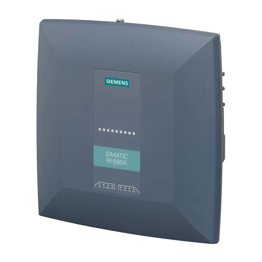
- Page 143 Readers 5.4 RF685R reader RF685R reader 5.4.1 Description 5.4.1.1 Overview The SIMATIC RF685R is a stationary reader in the UHF frequency band with an integrated antenna. An additional external UHF RFID antenna can be connected via an RP-TNC connector. The maximum RF power output is 2000°W at the external reader output. The interfaces (Ethernet, RS-422 to the power supply, M12 digital I/O interface) are located along the narrow lower front edge.
- Page 144 Readers 5.4 RF685R reader 5.4.1.2 Ordering data Table 5- 20 Ordering data RF685R Product Article number RF685R (ETSI) 6GT2811-6CA10-0AA0 RF685R (FCC) 6GT2811-6CA10-1AA0 RF685R (CMIIT) 6GT2811-6CA10-2AA0 RF685R (ARIB) 6GT2811-6CA10-4AA0 Table 5- 21 Ordering data accessories Product Article number Antenna mounting kit 6GT2890-0AA00 Holder set for securing the reader 6GT2890-0AB00...
- Page 145 Readers 5.4 RF685R reader Product Article number Set of protective caps 6GT2898-4AA10 Contains 3 protective caps for antenna output, one protec- tive cap for digital I/O interface and 2 protective caps for Ethernet/PROFINET (required for IP65 degree of protec- tion when some connectors are unused) DVD "Ident Systems Software &...
- Page 146 Readers 5.4 RF685R reader Wiring diagram M12 connector (cable end) You need to assemble your reader connecting cable (6GT2891-0CH50) with a suitable connector that fits the interface shown above. Keep to the following wiring diagram: Figure 5-19 M12 connector wiring diagram 5.4.1.4 Connection scheme for the digital I/O interface Connection possibilities...
- Page 147 Readers 5.4 RF685R reader The following diagrams illustrate various connection possibilities. Note Minimum time between changes Note that changes on the I/O interface that are not applied for at least 1.5 seconds are not detected by the reader. Voltage infeed from internal source (no electrical isolation) Figure 5-20 Circuit example 1: Digital inputs Alternative connection possibilities:...
- Page 148 Readers 5.4 RF685R reader Voltage infeed from external source Figure 5-21 Circuit example 2: Digital inputs Voltage infeed from external source with various voltages Figure 5-22 Circuit example 3: Digital inputs SIMATIC RF600 System Manual, 10/2016, J31069-D0171-U001-A19-7618...
- Page 149 Readers 5.4 RF685R reader Voltage infeed from internal source Figure 5-23 Circuit example 4: Digital outputs Alternative connection possibilities: ● Pin 1 GND to pin 3 DO common ● Pin 2 (VCC) to busbar outputs SIMATIC RF600 System Manual, 10/2016, J31069-D0171-U001-A19-7618...
- Page 150 Readers 5.4 RF685R reader Voltage infeed from external source Figure 5-24 Circuit example 5: Digital outputs Voltage infeed from an external source is shown here for 12°V as an example. Other voltages are also permissible. SIMATIC RF600 System Manual, 10/2016, J31069-D0171-U001-A19-7618...
- Page 151 Readers 5.4 RF685R reader Voltage infeed from external source with various voltages Figure 5-25 Circuit example 6: Digital outputs 5.4.1.5 Pin assignment 24 VDC (RS-422) Wire colors Assignment Device end 8-pin M12 White + 24 V Brown - Transmit Green Yellow + Transmit Gray...
- Page 152 Readers 5.4 RF685R reader Note Requirement for external power sources The reader must only be supplied with power by power supply units that meet the requirements of LPS (Limited Power Source) and NEC Class 2. Remark The cable with open cable ends (6GT2891-4EHx0) has an 8-pin M12 plug at one end, the other end of the cable id "open".
- Page 153 Readers 5.4 RF685R reader 5.4.1.7 Grounding connection On the top of the reader there is a blind drill hole (M4 x 8) for grounding. Tighten the screw with a torque of ≃ 1.5 Nm. WARNING Hazardous voltage due to lightning strikes Death or serious injury may occur as a result of lightning strikes to antennas mounted outside buildings.
- Page 154 5.4 RF685R reader Ground connection Hexagon-head screw Flat washer Cable lug Contact washer: To make ground contact, use contact wash- ers according to the Siemens standard: SN 70093-6-FStflNnnc- 480h, Siemens item no.: H70093-A60-Z3 Ground connection 5.4.2 Planning operation 5.4.2.1 Internal antenna Minimum mounting clearances of two readers The RF685R has an adjustable antenna (linear horizontal or linear vertical).
- Page 155 Readers 5.4 RF685R reader Antenna diagram for RF685R (ETSI) The following radiation diagrams show the directional characteristics of the internal antenna of the RF685R (ETSI) reader. For the spatial presentation of the directional characteristics, the vertical plane (azimuth section) as well as the horizontal plane (elevation section) must be considered.
- Page 156 Readers 5.4 RF685R reader Radiation diagram (Azimuth section) Figure 5-26 Azimuth section SIMATIC RF600 System Manual, 10/2016, J31069-D0171-U001-A19-7618...
- Page 157 Readers 5.4 RF685R reader Radiation diagram (elevation section) Figure 5-27 Elevation section SIMATIC RF600 System Manual, 10/2016, J31069-D0171-U001-A19-7618...
- Page 158 Readers 5.4 RF685R reader Radiation diagram circular Figure 5-28 Circular section Overview of the antenna parameters Table 5- 23 Maximum linear electrical aperture angle at 865 MHz: Polarization Circular polariza- tion Linear vertical Linear horizontal Azimuth section 64° 61° 65° Elevation section 64°...
- Page 159 Readers 5.4 RF685R reader Antenna diagram for RF685R (FCC) The following radiation diagrams show the directional characteristics of the internal antenna of the RF685R (FCC) reader. For the spatial presentation of the directional characteristics, the vertical plane (azimuth section) as well as the horizontal plane (elevation section) must be considered.
- Page 160 Readers 5.4 RF685R reader Radiation diagram (Azimuth section) Figure 5-29 Azimuth section SIMATIC RF600 System Manual, 10/2016, J31069-D0171-U001-A19-7618...
- Page 161 Readers 5.4 RF685R reader Radiation diagram (elevation section) Figure 5-30 Elevation section SIMATIC RF600 System Manual, 10/2016, J31069-D0171-U001-A19-7618...
- Page 162 Readers 5.4 RF685R reader Radiation diagram (circular) Figure 5-31 Circular section Overview of the antenna parameters Table 5- 24 Maximum linear electrical aperture angle at 915 MHz: Polarization Circular polariza- tion Linear vertical Linear horizontal Azimuth section 74° 64° 73° Elevation section 70°...
- Page 163 Readers 5.4 RF685R reader Interpretation of directional radiation patterns The following overview table will help you with the interpretation of directional radiation patterns. The table shows which dBi values correspond to which read/write ranges (in %): You can read the radiated power depending on the reference angle from the directional radiation patterns, and thus obtain information on the read/write range with this reference angle with regard to a transponder.
- Page 164 Readers 5.4 RF685R reader 5.4.3 Installation/mounting Requirement WARNING Checking the bearing load Make sure that the wall or ceiling can hold four times the total weight of the device. NOTICE Close unused connectors Note that the readers only have the specified degree of protection when all connectors are in use or when unused connectors are closed with the protective caps.
- Page 165 Readers 5.4 RF685R reader Mounting the reader on a DIN/standard rail Table 5- 25 DIN rail mounting Description 1. Place the spring in the groove. 2. Mount the holder using the supplied Torx screws. When mounting the holder, make sure that the angled tip is positioned above the spring in the groove.
- Page 166 Readers 5.4 RF685R reader Description 3. Fit the lower part of the locking mechanism of the reader into the DIN rail. To be able to mount the reader on or remove it from the DIN rail, pull down the holder mounted in step 2.
- Page 167 Readers 5.4 RF685R reader Table 5- 26 Installation on a standard rail Description 1. Mount the two adapter pieces using the supplied Torx screws. 2. Fit the upper part of the locking mechanism of the reader into the standard rail. 3.
- Page 168 Readers 5.4 RF685R reader 5.4.4 Configuration/integration An Ethernet interface is available for integrating the device into system environments/networks. The RF685R can be configured via the Ethernet interface and with direct connection to the PC. You can configure and program the reader using the following tools: ●...
- Page 169 Readers 5.4 RF685R reader 5.4.5 Technical specifications Table 5- 27 Technical specifications of the RF685R reader with RS-422 interface 6GT2811-6CA10-xAA0 Product type designation SIMATIC RF685R Radio frequencies Operating frequency ETSI 865 to 868 MHz • • 902 to 928 MHz •...
- Page 170 Readers 5.4 RF685R reader 6GT2811-6CA10-xAA0 Channel spacing ETSI 600 kHz • • 500 kHz • • CMIIT 250 kHz • • ARIB 200 kHz • • Modulation methods ASK: DSB modulation & PR-ASK modulation encoding, Manchester or Pulse Interval (PIE) Multitag capability Typical transmission time per byte Write access...
- Page 171 Readers 5.4 RF685R reader 6GT2811-6CA10-xAA0 Mechanical specifications Material Upper part of housing Pocan • • Lower part of housing Aluminum • • Color Upper part of housing TI-Grey • • Lower part of housing Silver • • Permitted ambient conditions Ambient temperature During operation -25 ℃...
- Page 172 Readers 5.4 RF685R reader 5.4.6 Dimension drawing Figure 5-33 Dimension drawing RF685R All dimensions in mm (± 0.5 mm tolerance) SIMATIC RF600 System Manual, 10/2016, J31069-D0171-U001-A19-7618...
- Page 173 Readers 5.4 RF685R reader 5.4.7 Certificates and approvals Note Marking on the readers according to specific approval The certificates and approvals listed here apply only if the corresponding mark is found on the readers. Table 5- 28 6GT2811-6CA10-0AA0 Labeling Description Conformity with the RED directive 2014/53/EU Conformity with the RoHS directive 2011/65/EU South Africa radio approval:...
- Page 174 Readers 5.4 RF685R reader Labeling Description Brazil radio approval Marking on the reader (6GT2811-6CA10-1AA0): Statement about approval: Este equipamento opera em caráter secundário, isto é, não tem direito à proteção contra interferência prejudicial, mesmo de es- tações do mesmo tipo e não pode causar interferência a sistemas operando em caráter primário.
- Page 175 Readers 5.4 RF685R reader 5.4.7.1 FCC information Siemens SIMATIC RF685R (FCC): 6GT2811-6CA10-1AA0 FCC ID: NXW-RF600R2 This device complies with part 15 of the FCC rules. Operation is subject to the following two conditions: (1) This device may not cause harmful interference, and (2) this device must accept any interference received, including interference that may cause undesired operation.
- Page 176 Readers 5.5 RF650M reader 5.4.7.2 IC-FCB information Siemens SIMATIC RF685R (FCC): 6GT2811-6CA10-1AA0 This device complies with Industry Canada licence-exempt RSS standard(s). Operation is subject to the following two conditions: (1) This device may not cause interference, and (2) this device must accept any interference, including interference that may cause undesired operation of the device.
- Page 177 Readers 5.5 RF650M reader RF650M reader 5.5.1 Description SIMATIC RF650M expands the RF600 identification system with a powerful mobile reader for applications in the areas of logistics, production and service. In addition, it is an indispensable aid for startup and testing. 5.5.2 Field of application and features Device variants for different frequency ranges...
- Page 178 ● Easy creation of your own RFID applications with the software "Application Interface" (API) You will find further information on the RF650M handheld terminal in the operating instructions "SIMATIC RF650M mobile handheld terminal (https://support.industry.siemens.com/cs/ww/en/view/109475735)". SIMATIC RF600 System Manual, 10/2016, J31069-D0171-U001-A19-7618...
- Page 179 Antennas Overview The following table shows the most important features of the RF600 antennas at a glance: Table 6- 1 Characteristics of the RF620A and RF660A antennas Features RF620A RF660A Material PA 12, silicon-free Frequency band 865-868 MHz 902-928 MHz 865-868 MHz 902-928 MHz Impedance...
- Page 180 Antennas 6.1 Overview Table 6- 2 Characteristics of the RF640A and RF642A antennas Features RF640A RF642A Material PA 12, silicon-free Frequency band 865-868 MHz 902-928 MHz 865-868 MHz 902-928 MHz Impedance 50 Ohm nominal Antenna gain 4 dBi (7 dBic) 4.3 dBi (7.3 dBic) 6 dBi 7 dBi...
- Page 181 Antennas 6.1 Overview Table 6- 3 Characteristics of the RF650A and RF680A antennas Characteristics RF650A RF680A Material Pocan DPCF2200, silicone free Frequency band 865-868 MHz 902-928 MHz 865-868 MHz 902-928 MHz Impedance 50 ohms nominal Antenna gain 4 dBi (7 dBic) 3.5 dBi (6.1 dBic) 3.5 dBi (6.1 dBic) 3.5 dBi (6.1 dBic)
- Page 182 Antennas 6.2 RF620A antenna RF620A antenna 6.2.1 Characteristics SIMATIC RF620A Characteristics Area of application The SIMATIC RF620A is an antenna with a compact design suitable for industry. It is suitable for UHF transponders with normal (far field) antenna char- acteristics, e.g. SIMATIC RF630L, SIMATIC RF620T.
- Page 183 Antennas 6.2 RF620A antenna 6.2.2 Ordering data Table 6- 4 Ordering data RF620A Product Article number SIMATIC RF620A (ETSI) 6GT2812-1EA00 SIMATIC RF620A (FCC) 6GT2812-1EA01 Table 6- 5 Ordering data accessories Product Article number Connecting cable between 1 m (cable loss 0.5 dB) 6GT2815-0BH10 reader and antenna 3 m (cable loss 1.0 dB)
- Page 184 Requirement Note Use of Siemens antenna cable To ensure optimum functioning of the antenna, it is recommended that a Siemens antenna cable is used in accordance with the list of accessories. Strain relief The antenna cable is provided with strain relief as shown in the following diagram: ①...
- Page 185 Antennas 6.2 RF620A antenna Cable designa- Article number Length [m] Cable loss Bending radi- Bending cycle tion [dB] us [mm] Antenna cable 6GT2815-0BN15 (suitable for drag chains) Antenna cable 6GT2815-0BN20 Antenna cable 6GT2815-0BN40 With cables capable of being used in drag chains, 100,000 bending cycles at a bending radius of 100 mm and a bend through ±...
- Page 186 Antennas 6.2 RF620A antenna Operation in the USA, Canada Note Limitation of the radiated power to 4000 mW EIRP (36 dBm EIRP) To meet the FCC and IC requirements, the radiated power may not exceed 4000 mW EIRP (36 dBm EIRP). Therefore the system must satisfy the following relation: •...
- Page 187 Antennas 6.2 RF620A antenna Alignment The following diagram shows the optimum alignment of the RF600 transponders to the RF620A antenna. Figure 6-3 Antenna/transponder alignment SIMATIC RF600 System Manual, 10/2016, J31069-D0171-U001-A19-7618...
- Page 188 Antennas 6.2 RF620A antenna Angle deviation diagram for alignment The following diagram shows the dependence of the following factors. ● Alignment angle of transponder to antenna ● Maximum range of antenna Figure 6-4 Angle deviation diagram for alignment SIMATIC RF600 System Manual, 10/2016, J31069-D0171-U001-A19-7618...
- Page 189 Antennas 6.2 RF620A antenna 6.2.6.2 Antenna pattern ETSI Directional radiation pattern Europe (ETSI) The directional radiation pattern is shown for nominal alignment and a center frequency of 866.3 MHz. The nominal antenna alignment is given when the antenna elevation is provided as shown in the following figure.
- Page 190 Antennas 6.2 RF620A antenna Directional radiation pattern ETSI on metallic mounting surface (15 cm x 15 cm) Pattern of the vertical plane of the antenna Pattern of the horizontal plane of the antenna Figure 6-6 Directional radiation pattern RF620A ETSI on metallic mounting surface SIMATIC RF600 System Manual, 10/2016, J31069-D0171-U001-A19-7618...
- Page 191 Antennas 6.2 RF620A antenna Directional radiation pattern ETSI on non-metallic mounting surface Pattern of the vertical plane of the antenna Pattern of the horizontal plane of the antenna Figure 6-7 Directional radiation pattern RF620A ETSI on non-metallic mounting surface SIMATIC RF600 System Manual, 10/2016, J31069-D0171-U001-A19-7618...
- Page 192 Antennas 6.2 RF620A antenna 6.2.6.3 Antenna pattern FCC Directional radiation pattern USA (FCC) The directional radiation pattern is shown for nominal alignment and a center frequency of 915 MHz. Figure 6-8 Reference system The half-power beamwidth of the antenna is defined by the angle between the two -3 dB points (corresponding to half the power referred to the maximum power).
- Page 193 Antennas 6.2 RF620A antenna Directional radiation pattern of the RF620A (FCC) on metallic mounting surface (15 cm x 15 cm) Pattern of the vertical plane of the antenna Pattern of the horizontal plane of the antenna Figure 6-9 Directional radiation pattern of the RF620A (FCC) on metallic mounting surface SIMATIC RF600 System Manual, 10/2016, J31069-D0171-U001-A19-7618...
- Page 194 Antennas 6.2 RF620A antenna Directional radiation pattern of the RF620A (FCC) on non-metallic mounting surface Pattern of the vertical plane of the antenna Pattern of the horizontal plane of the antenna Figure 6-10 Directional radiation pattern of the RF620A (FCC) on non-metallic mounting surface SIMATIC RF600 System Manual, 10/2016, J31069-D0171-U001-A19-7618...
- Page 195 Antennas 6.2 RF620A antenna 6.2.6.4 Interpretation of directional radiation patterns The following overview table will help you with the interpretation of directional radiation patterns. The table shows which dBi values correspond to which read/write ranges (in %): You can read the radiated power depending on the reference angle from the directional radiation patterns, and thus obtain information on the read/write range with this reference angle with regard to a transponder.
- Page 196 Antennas 6.2 RF620A antenna 6.2.7 Technical data Table 6- 7 Technical specifications for the RF620A antenna 6GT2812-1EA0x Product type designation SIMATIC RF620A Radio frequencies Operating frequency ETSI 865 to 868 MHz • • 902 to 928 MHz • • Maximum radiated power ETSI ≤...
- Page 197 Antennas 6.2 RF620A antenna 6GT2812-1EA0x Interfaces Plug connection 30 cm coaxial cable with RTNC coupling (for connection of the antenna cable) Mechanical specifications Material PA 12 Color Pastel turquoise Tightening torque (at room temperature) ≤ 2 Nm Permitted ambient conditions Ambient temperature During operation -20 to +70 ℃...
- Page 198 Antennas 6.2 RF620A antenna 6.2.8 Dimension drawing Figure 6-11 Dimension drawing RF620A All dimensions in mm SIMATIC RF600 System Manual, 10/2016, J31069-D0171-U001-A19-7618...
- Page 199 Antennas 6.2 RF620A antenna 6.2.9 Approvals & certificates Table 6- 8 6GT2812-1EA00 Labeling Designation Conformity with the RED directive 2014/53/EU Conformity with the RoHS directive 2011/65/EU Table 6- 9 6GT2812-1EA01 Labeling Description FCC CFR 47, Part 15 sections 15.247 Radio Frequency Interference Statement This equipment has been tested and found to comply with the limits Federal Communications for a Class B digital device, pursuant to Part 15 of the FCC Rules.
- Page 200 Antennas 6.3 Antenna RF640A Antenna RF640A 6.3.1 Characteristics SIMATIC RF640A Features Field of application The SIMATIC RF640A is a universal UHF antenna of compact, industry- standard design with medium range. Frequency range 865 to 928 MHz Polarization RH circular Suitable for RF600 transponders that can pass in parallel with the antenna regardless of their orienta- tion.
- Page 201 Antennas 6.3 Antenna RF640A 6.3.2 Ordering data Table 6- 10 Ordering data RF640A Product Article number SIMATIC RF640A 6GT2812-0GA08 Table 6- 11 Ordering data accessories Product Article number Connecting cable between 1 m (cable loss 0.5 dB) 6GT2815-0BH10 reader and antenna 3 m (cable loss 1.0 dB) 6GT2815-0BH30 5 m, suitable for drag chains...
- Page 202 Requirement Note Use of Siemens antenna cable To ensure optimum functioning of the antenna, it is recommended that a Siemens antenna cable is used in accordance with the list of accessories. Strain relief The antenna cable is provided with strain relief as shown in the following diagram: ①...
- Page 203 Antennas 6.3 Antenna RF640A Table 6- 12 Bending radii and bending cycles of the antenna cable Cable designa- Article number Length [m] Cable loss Bending radi- Bending cycle tion [dB] us [mm] RF640A con- Fixed connection necting cable to antenna Antenna cable 6GT2815-0BH10 Antenna cable...
- Page 204 Antennas 6.3 Antenna RF640A Operation in China By setting a max. radiated power of 1460 mW ERP (or 31.35 dBm ERP, 2400 mW EIRP, 33.8 dBm EIRP), an RF640A antenna gain of 4.3 dBi (7.3 dBic) and taking into account the cable loss associated with the antenna cable (see table (Page 202)), the radiated power of the reader is correctly configured.
- Page 205 Antennas 6.3 Antenna RF640A Operation in China By setting a max. radiated power of 2000 mW ERP (or 33 dBm ERP, 3250 mW EIRP, 35 dBm EIRP), an RF640A antenna gain of 4.3 dBi (7.3 dBic) and taking into account the cable loss associated with the antenna cable (see table (Page 202)), the radiated power of the reader is correctly configured.
- Page 206 Antennas 6.3 Antenna RF640A 6.3.6 Antenna patterns 6.3.6.1 Antenna radiation patterns in the ETSI frequency band Directional radiation pattern Europe (ETSI) The directional radiation pattern is shown for nominal alignment and a center frequency of 866.3 MHz. The nominal antenna alignment is given when the antenna elevation is provided as shown in the following figure.
- Page 207 Antennas 6.3 Antenna RF640A Directional radiation patterns in the ETSI frequency band Polarization axis and axis of symmetry are parallel In a configuration based on the following directional radiation pattern of the antenna, the axis of symmetry of the antenna and the polarization axis of the transponder are parallel. SIMATIC RF600 System Manual, 10/2016, J31069-D0171-U001-A19-7618...
- Page 208 Antennas 6.3 Antenna RF640A Pattern of the vertical plane of the antenna Pattern of the horizontal plane of the antenna Figure 6-14 The RF640A directional radiation pattern in the ETSI frequency band, polarization axis of the transponder, and axis of symmetry of the antenna are parallel to each other. SIMATIC RF600 System Manual, 10/2016, J31069-D0171-U001-A19-7618...
- Page 209 Antennas 6.3 Antenna RF640A Polarization axis and axis of symmetry are orthogonal to each other In a configuration based on the following directional radiation pattern of the antenna, the axis of symmetry of the antenna and the polarization axis of the transponder are orthogonal to each other.
- Page 210 Antennas 6.3 Antenna RF640A Pattern of the vertical plane of the antenna Pattern of the horizontal plane of the antenna Figure 6-15 The RF640A directional radiation pattern in the ETSI frequency band, axis of symmetry of the antenna, and polarization axis of the transponder are orthogonal to each other SIMATIC RF600 System Manual, 10/2016, J31069-D0171-U001-A19-7618...
- Page 211 Antennas 6.3 Antenna RF640A 6.3.6.2 Antenna radiation patterns in the FCC frequency band Directional radiation pattern USA (FCC) The directional radiation pattern is shown for nominal alignment and a center frequency of 915 MHz. Figure 6-16 Reference system The half-power beam width of the antenna is defined by the angle between the two -3 dB points (corresponding to half the power referred to the maximum power).
- Page 212 Antennas 6.3 Antenna RF640A Directional radiation pattern in the FCC frequency band Polarization axis and axis of symmetry are parallel In the following directional radiation pattern of the antenna, the axis of symmetry of the antenna and the polarization axis of the transponder are parallel. SIMATIC RF600 System Manual, 10/2016, J31069-D0171-U001-A19-7618...
- Page 213 Antennas 6.3 Antenna RF640A Pattern of the vertical plane of the antenna Pattern of the horizontal plane of the antenna Figure 6-17 The RF640A directional radiation pattern in the FCC frequency band, polarization axis of the transponder, and axis of symmetry of the antenna are parallel to each other SIMATIC RF600 System Manual, 10/2016, J31069-D0171-U001-A19-7618...
- Page 214 Antennas 6.3 Antenna RF640A Polarization axis and axis of symmetry are orthogonal to each other In the following directional radiation pattern of the antenna, the axis of symmetry of the antenna and the polarization axis of the transponder are orthogonal to each other. SIMATIC RF600 System Manual, 10/2016, J31069-D0171-U001-A19-7618...
- Page 215 Antennas 6.3 Antenna RF640A Pattern of the vertical plane of the antenna Pattern of the horizontal plane of the antenna Figure 6-18 The RF640A directional radiation pattern in the FCC frequency band, axis of symmetry of the antenna, and polarization axis of the transponder are orthogonal to each other SIMATIC RF600 System Manual, 10/2016, J31069-D0171-U001-A19-7618...
- Page 216 Antennas 6.3 Antenna RF640A 6.3.6.3 Interpretation of directional radiation patterns The following overview table will help you with the interpretation of directional radiation patterns. The table shows which dBi values correspond to which read/write ranges (in %): You can read the radiated power depending on the reference angle from the directional radiation patterns, and thus obtain information on the read/write range with this reference angle with regard to a transponder.
- Page 217 Antennas 6.3 Antenna RF640A 6.3.7 Technical data Table 6- 13 Technical specifications for the RF640A antenna 6GT2812-0GA08 Product type designation SIMATIC RF640A Radio frequencies Operating frequency 865 to 928 MHz Maximum radiated power ETSI RF650R: ≤ 1300 mW ERP • •...
- Page 218 Antennas 6.3 Antenna RF640A 6GT2812-0GA08 Electrical data Range See section "Maximum read/write ranges of transponders (Page 297)" Impedance 50 Ω Polarization Circular VSWR (standing wave ratio) ETSI ≤ 1.25 • • ≤ 1.6 • • Power Interfaces Plug connection 30 cm coaxial cable with RTNC coupling (for connection of the antenna cable) Mechanical specifications Material...
- Page 219 Antennas 6.3 Antenna RF640A 6.3.8 Dimension drawing Figure 6-19 Dimension drawing RF640A All dimensions in mm SIMATIC RF600 System Manual, 10/2016, J31069-D0171-U001-A19-7618...
- Page 220 Antennas 6.3 Antenna RF640A 6.3.9 Approvals & certificates Table 6- 14 6GT2812-0GA08 Labeling Description Conformity with the RED directive 2014/53/EU Conformity with the RoHS directive 2011/65/EU Table 6- 15 6GT2812-0GA08 Labeling Description FCC CFR 47, Part 15 sections 15.247 Radio Frequency Interference Statement This equipment has been tested and found to comply with the limits Federal Communications for a Class B digital device, pursuant to Part 15 of the FCC Rules.
- Page 221 Antennas 6.4 Antenna RF642A Antenna RF642A 6.4.1 Characteristics SIMATIC RF642A Features Field of application The SIMATIC RF642A is a universal UHF antenna of compact, industry- standard design with medium range. Frequency range 865 to 928 MHz Polarization Linear polarization Suitable for RF600 transponders that are uniformly aligned while directed past the antenna.
- Page 222 Antennas 6.4 Antenna RF642A 6.4.2 Ordering data Table 6- 16 Ordering data RF642A Product Article number SIMATIC RF642A 6GT2812-1GA08 Table 6- 17 Ordering data accessories Product Article number Connecting cable between 1 m (cable loss 0.5 dB) 6GT2815-0BH10 reader and antenna 3 m (cable loss 1.0 dB) 6GT2815-0BH30 5 m, suitable for drag chains...
- Page 223 Requirement Note Use of Siemens antenna cable To ensure optimum functioning of the antenna, it is recommended that a Siemens antenna cable is used in accordance with the list of accessories. Strain relief The antenna cable is provided with strain relief as shown in the following diagram: ①...
- Page 224 Antennas 6.4 Antenna RF642A Table 6- 18 Bending radii and bending cycles of the antenna cable Cable designa- Article number Length [m] Cable loss Bending radi- Bending cycle tion [dB] us [mm] RF642A con- Fixed connection necting cable to antenna Antenna cable 6GT2815-0BH10 Antenna cable...
- Page 225 Antennas 6.4 Antenna RF642A 6.4.5 Antenna parameter assignment 6.4.5.1 Alignment of transponders to the antenna Polarization axis Since the RF642A antenna has linear polarization, it is necessary to consider the alignment of the transponders with regard to the polarization axis of the antenna. The polarization axes of antenna and transponder must always be parallel.
- Page 226 Antennas 6.4 Antenna RF642A Alignment The following diagram shows the optimum alignment of the RF600 transponders to the RF642A antenna. Figure 6-22 Antenna/transponder alignment SIMATIC RF600 System Manual, 10/2016, J31069-D0171-U001-A19-7618...
- Page 227 Antennas 6.4 Antenna RF642A Angle deviation diagram for alignment The following diagram shows the dependence of the following factors. ● Alignment angle of transponder to antenna ● Maximum range of antenna Figure 6-23 Angle deviation diagram for alignment SIMATIC RF600 System Manual, 10/2016, J31069-D0171-U001-A19-7618...
- Page 228 Antennas 6.4 Antenna RF642A 6.4.5.2 Setting RF642A parameters for RF650R Operation within the EU according to DIN EN 302208 V1.4.1 Note Limitation of the radiated power according to DIN EN 302208 V1.4.1 RF600 systems that are put into operation within the EU, EFTA, or Turkey (ETSI) can be operated with an RF642A antenna with a maximum radiated power of 2000 mW ERP (or 33 dBm ERP, 3250 mW EIRP, 35 dBm EIRP).
- Page 229 Antennas 6.4 Antenna RF642A 6.4.5.3 Setting RF642A parameters for RF680R/RF685R Operation within the EU according to DIN EN 302208 V1.4.1 Note Limitation of the radiated power according to DIN EN 302208 V1.4.1 RF600 systems that are put into operation within the EU, EFTA, or Turkey (ETSI) can be operated with an RF642A antenna with a maximum radiated power of 2000 mW ERP (or 33 dBm ERP, 3250 mW EIRP, 35 dBm EIRP).
- Page 230 Antennas 6.4 Antenna RF642A By selecting the correct country profile/frequency range and setting the radiated power (see technical specifications of the reader being used) and setting the parameters for antenna gain and cable loss, the maximum radiated power will not be exceeded. 6.4.6 Antenna patterns 6.4.6.1...
- Page 231 Antennas 6.4 Antenna RF642A Directional radiation pattern in the ETSI frequency band Pattern of the vertical plane of the antenna Pattern of the horizontal plane of the antenna Figure 6-25 Directional radiation pattern of RF642A in the ETSI frequency band SIMATIC RF600 System Manual, 10/2016, J31069-D0171-U001-A19-7618...
- Page 232 Antennas 6.4 Antenna RF642A 6.4.6.2 Antenna radiation patterns in the FCC frequency band Directional radiation pattern USA (FCC) The directional radiation pattern is shown for nominal alignment and a center frequency of 915 MHz. Figure 6-26 Reference system The half-power beam width of the antenna is defined by the angle between the two -3 dB points (corresponding to half the power referred to the maximum power).
- Page 233 Antennas 6.4 Antenna RF642A Directional radiation pattern of the RF642A in the FCC frequency band Pattern of the vertical plane of the antenna Pattern of the horizontal plane of the antenna Figure 6-27 Directional radiation pattern of the RF642A in the FCC frequency band SIMATIC RF600 System Manual, 10/2016, J31069-D0171-U001-A19-7618...
- Page 234 Antennas 6.4 Antenna RF642A 6.4.6.3 Interpretation of directional radiation patterns The following overview table will help you with the interpretation of directional radiation patterns. The table shows which dBi values correspond to which read/write ranges (in %): You can read the radiated power depending on the reference angle from the directional radiation patterns, and thus obtain information on the read/write range with this reference angle with regard to a transponder.
- Page 235 Antennas 6.4 Antenna RF642A 6.4.7 Technical data Table 6- 19 Technical specifications for the RF642A antenna 6GT2812-1GA08 Product type designation SIMATIC RF642A Radio frequencies Operating frequency 865 to 928 MHz Maximum radiated power ETSI RF650R: ≤ 1900 mW ERP • •...
- Page 236 Antennas 6.4 Antenna RF642A 6GT2812-1GA08 Interfaces Plug connection 30 cm coaxial cable with RTNC coupling (for connection of the antenna cable) Mechanical specifications Material PA 12 Color Pastel turquoise Tightening torque (at room temperature) ≤ 2 Nm Permitted ambient conditions Ambient temperature During operation -25 to +75 °C...
- Page 237 Antennas 6.4 Antenna RF642A 6.4.8 Dimension drawing Figure 6-28 Dimensional drawing of RF642A All dimensions in mm SIMATIC RF600 System Manual, 10/2016, J31069-D0171-U001-A19-7618...
- Page 238 Antennas 6.4 Antenna RF642A 6.4.9 Approvals & certificates Table 6- 20 6GT2812-1GA08 Labeling Description Conformity with the RED directive 2014/53/EU Conformity with the RoHS directive 2011/65/EU Table 6- 21 6GT2812-1GA08 Labeling Description FCC CFR 47, Part 15 sections 15.247 Radio Frequency Interference Statement This equipment has been tested and found to comply with the limits Federal Communications for a Class B digital device, pursuant to Part 15 of the FCC Rules.
- Page 239 Antennas 6.5 RF650A antenna RF650A antenna 6.5.1 Characteristics SIMATIC RF650A Features Field of application SIMATIC RF650A is a circular an- tenna of medium size for universal use in industrial applications in pro- duction and logistics. Frequency band 865 to 928 MHz Polarization RH circular Suitable for RF600 transponders...
- Page 240 Antennas 6.5 RF650A antenna 6.5.2 Ordering data Table 6- 22 Ordering data RF650A Product Article number SIMATIC RF650A 6GT2812-0GB08 Table 6- 23 Ordering data accessories Product Article number Connecting cable between 1 m (cable loss 0.5 dB) 6GT2815-0BH10 reader and antenna 3 m (cable loss 1.0 dB) 6GT2815-0BH30 5 m, suitable for drag chains...
- Page 241 6GT2815-0BH10 (length 1m), since this cable has the lowest cable loss. Requirement Note Use of Siemens antenna cables To ensure optimum functioning of the antenna, it is recommended that a Siemens antenna cable be used in accordance with the list of accessories. SIMATIC RF600 System Manual, 10/2016, J31069-D0171-U001-A19-7618...
- Page 242 Antennas 6.5 RF650A antenna Strain relief The antenna cable is provided with strain relief as shown in the following diagram: ① RF600 antenna cable ② Strain relief (should take place at this position) Figure 6-29 RF 650A strain relief Table 6- 24 Bending radii and bending cycles of the antenna cable Cable designa- Article number...
- Page 243 Antennas 6.5 RF650A antenna 6.5.5 Antenna parameter assignment 6.5.5.1 Setting RF650A parameters for RF650R, RF680R and RF685R Operation within the EU, EFTA, or Turkey Note Limitation of the radiated power according to EN 302 208 V1.4.1 RF600 systems that are put into operation within the EU, EFTA, or Turkey (ETSI) can be operated with an RF650A antenna with a maximum radiated power of 2000 mW ERP (or 33 dBm ERP, 3250 mW EIRP, 35 dBm EIRP).
- Page 244 Antennas 6.5 RF650A antenna 6.5.6 Antenna patterns Transponder alignment The RF650A antenna has a circular antenna. With a circular antenna the alignment of the antenna axis of symmetry changes between horizontal and vertical each time it transmits. For this reason the alignment of the transponder polarization axis (horizontal/vertical) is unimportant.
- Page 245 Antennas 6.5 RF650A antenna 6.5.6.1 Antenna patterns in the ETSI frequency band Directional radiation pattern The directional radiation pattern is shown for nominal alignment and a center frequency of 866.3 MHz. The nominal antenna alignment is given when the antenna elevation is provided as shown in the following figure.
- Page 246 Antennas 6.5 RF650A antenna Directional radiation patterns in the ETSI frequency band Radiation diagram (circular) in the ETSI frequency band Pattern of the vertical plane of the antenna Pattern of the horizontal plane of the antenna Figure 6-32 Directional radiation pattern of RF650A in the ETSI frequency band SIMATIC RF600 System Manual, 10/2016, J31069-D0171-U001-A19-7618...
- Page 247 Antennas 6.5 RF650A antenna 6.5.6.2 Antenna patterns in the FCC frequency band Antenna pattern FCC The directional radiation pattern is shown for nominal alignment and a center frequency of 915 MHz. Figure 6-33 Reference system The half-power beam width of the antenna is defined by the angle between the two -3 dB points (corresponding to half the power referred to the maximum power).
- Page 248 Antennas 6.5 RF650A antenna Directional radiation pattern in the FCC frequency band Radiation diagram (circular) in the FCC frequency band Pattern of the vertical plane of the antenna Pattern of the horizontal plane of the antenna Figure 6-34 Directional radiation pattern of the RF650A in the FCC frequency band SIMATIC RF600 System Manual, 10/2016, J31069-D0171-U001-A19-7618...
- Page 249 Antennas 6.5 RF650A antenna 6.5.6.3 Interpretation of directional radiation patterns The following overview table will help you with the interpretation of directional radiation patterns. The table shows which dBi values correspond to which read/write ranges (in %): You can read the radiated power depending on the reference angle from the directional radiation patterns, and thus obtain information on the read/write range with this reference angle with regard to a transponder.
- Page 250 Antennas 6.5 RF650A antenna 6.5.7 Technical data Table 6- 26 Technical specifications for the RF650A antenna 6GT2812-0GB08 Product type designation SIMATIC RF650A Radio frequencies Operating frequency 865 to 928 MHz Maximum radiated power ETSI RF650R: ≤ 1365 mW ERP • •...
- Page 251 Antennas 6.5 RF650A antenna 6GT2812-0GB08 Interfaces Plug connection RTNC coupling (for connection of the anten- na cable) Mechanical specifications Material Pocan Color Pastel turquoise Tightening torque (at room temperature) ≤ 2 Nm Permitted ambient conditions Ambient temperature During operation -25 to +75 °C •...
- Page 252 Antennas 6.5 RF650A antenna 6.5.8 Dimension drawing Figure 6-35 Dimension drawing RF650A All dimensions in mm SIMATIC RF600 System Manual, 10/2016, J31069-D0171-U001-A19-7618...
- Page 253 Antennas 6.5 RF650A antenna 6.5.9 Approvals & certificates Table 6- 27 6GT2812-0GB08 Labeling Description Conformity with the RED directive 2014/53/EU Conformity with the RoHS directive 2011/65/EU Table 6- 28 6GT2812-0GB08 Labeling Description FCC CFR 47, Part 15 sections 15.247 Radio Frequency Interference Statement This equipment has been tested and found to comply with the limits Federal Communications for a Class B digital device, pursuant to Part 15 of the FCC Rules.
- Page 254 Antennas 6.6 RF660A antenna RF660A antenna 6.6.1 Characteristics SIMATIC RF660A Features Field of application The SIMATIC RF660A is a universal medium range UHF antenna with a compact design suitable for use in industry. Frequency ranges 865 to 928 MHz (ETSI) •...
- Page 255 Antennas 6.6 RF660A antenna Ordering data Table 6- 29 Ordering data RF660A Product Article number SIMATIC RF660A (ETSI) 6GT2812-0AA00 SIMATIC RF660A (FCC) 6GT2812-0AA01 Table 6- 30 Ordering data accessories Product Article number Connecting cable between 1 m (cable loss 0.5 dB) 6GT2815-0BH10 reader and antenna 3 m (cable loss 1.0 dB)
- Page 256 6GT2815-0BH10 (length 1m), since this cable has the lowest cable loss. Requirement Note Use of Siemens antenna cable To ensure optimum functioning of the antenna, it is recommended that a Siemens antenna cable is used in accordance with the list of accessories. Figure 6-36 Rear of antenna with RTNC connection...
- Page 257 Antennas 6.6 RF660A antenna Cable designa- Article number Length [m] Cable loss Bending radi- Bending cycle tion [dB] us [mm] Antenna cable 6GT2815-0BN20 Antenna cable 6GT2815-0BN40 With cables capable of being used in drag chains, 100,000 bending cycles at a bending radius of 100 mm and a bend through ±...
- Page 258 Antennas 6.6 RF660A antenna Operation in the USA, Canada Note Limitation of the transmit power to 4000 mW EIRP (36 dBm EIRP) To meet the FCC and IC requirements, the radiated power may not exceed 4000 mW EIRP (36 dBm EIRP). Therefore the system must satisfy the following relation: •...
- Page 259 Antennas 6.6 RF660A antenna Operation in the USA, Canada Note Limitation of the transmit power to 4000 mW EIRP (36 dBm EIRP) To meet the FCC and IC requirements, the radiated power may not exceed 4000 mW EIRP (36 dBm EIRP). Therefore the system must satisfy the following relation: •...
- Page 260 Antennas 6.6 RF660A antenna 6.6.5 Antenna patterns Spatial directional radiation pattern The following schematic diagram shows the main and auxiliary fields of the RF660A antenna in free space in the absence of reflecting/absorbing materials. Please note that the diagram is not to scale. The recommended working range lies within the main field that is shown in green.
- Page 261 Antennas 6.6 RF660A antenna Radiation diagram (horizontal) Europe (ETSI) The radiation diagram is shown for horizontal alignment and for a center frequency of 865 MHz. Horizontal antenna alignment is provided when the TNC connection on the antenna points vertically up or down. The radiating/receiving angle of the antenna is defined by the angle between the two -3 dB points (corresponding to half the power referred to the maximum performance at a 0°...
- Page 262 Antennas 6.6 RF660A antenna Figure 6-39 Directional radiation pattern of the antenna (at 915 MHz, horizontal alignment) 6.6.6 Technical data Table 6- 32 Technical specifications for the RF660A antenna 6GT2812-0AA0x Product type designation SIMATIC RF660A Radio frequencies Operating frequency ETSI 865 to 868 MHz •...
- Page 263 Antennas 6.6 RF660A antenna 6GT2812-0AA0x Antenna gain ETSI 7 dB (5 to 7 dBic) • • 6 dB (> 6 dBic) • • Opening angle for sending/receiving when mounted on a metal surface of 15 cm x 15 cm ETSI Horizontal plane: 55°...
- Page 264 Antennas 6.6 RF660A antenna 6GT2812-0AA0x Design, dimensions and weight Dimensions (H x W x D) 313 x 313 x 80 mm Weight 1.6 kg Standards, specifications, approvals Proof of suitability CE (ETSI EN 302208), FCC (Title 47, Part 15.247), cULus MTBF 228310 years The values differ for different dimensions/materials of the mounting surface.
- Page 265 Antennas 6.6 RF660A antenna 6.6.8 Approvals & certificates Table 6- 33 6GT2812-0AA00 Labeling Description Conformity with the RED directive 2014/53/EU Conformity with the RoHS directive 2011/65/EU Table 6- 34 6GT2812-0AA01 Labeling Description FCC CFR 47, Part 15 sections 15.247 Radio Frequency Interference Statement This equipment has been tested and found to comply with the limits Federal Communications for a Class B digital device, pursuant to Part 15 of the FCC Rules.
- Page 266 Antennas 6.7 RF680A antenna RF680A antenna NOTICE Note on release The use of the adaptive antenna SIMATIC RF680A with the readers RF650R, RF680R and RF685R as of version V2.2.0 (supplied as of 03/2016) is possible. You will find the version on the type plate of the device. 6.7.1 Characteristics SIMATIC RF680A...
- Page 267 Antennas 6.7 RF680A antenna LED status display The operating statuses of the antenna are displayed by an LED status display. The LED can adopt the colors green, red or yellow and the statuses off , on , flashing : Table 6- 35 Display of operating statuses of the antenna Meaning LED static for 1 second when the reader starts up:...
- Page 268 6GT2815-0BH10 (length 1 m) since this has the lowest cable loss. Requirement Note Use of Siemens antenna cables To ensure optimum functioning of the antenna, it is recommended that a Siemens antenna cable be used in accordance with the list of accessories. SIMATIC RF600 System Manual, 10/2016, J31069-D0171-U001-A19-7618...
- Page 269 Antennas 6.7 RF680A antenna Strain relief The antenna cable is provided with strain relief as shown in the following diagram: ① RF600 antenna cable ② Strain relief (should take place at this position) Figure 6-41 Strain relief Table 6- 38 Bending radii and bending cycles of the antenna cable Cable designa- Article number...
- Page 270 Antennas 6.7 RF680A antenna 6.7.5 Antenna parameter assignment 6.7.5.1 Parameter assignment of the RF680A for RF650R, RF680R and RF685R Operation within the EU, EFTA, or Turkey Note Limitation of the radiated power according to EN 302 208 V1.4.1 RF600 systems that are put into operation within the EU, EFTA, or Turkey (ETSI) can be operated with an RF680A antenna with a maximum radiated power of 2000 mW ERP (or 33 dBm ERP, 3250 mW EIRP, 35 dBm EIRP).
- Page 271 Antennas 6.7 RF680A antenna 6.7.6 Antenna patterns Transponder alignment The antenna RF680A has an adjustable antenna (circular or linear horizontal or linear vertical). With a circular antenna the alignment of the antenna axis of symmetry changes between horizontal and vertical each time it transmits. For this reason, with a circular antenna the alignment of the transponder polarization axis (horizontal/vertical) is unimportant.
- Page 272 Antennas 6.7 RF680A antenna 6.7.6.1 Antenna patterns in the ETSI frequency band Directional radiation pattern The directional radiation pattern is shown for nominal alignment and a center frequency of 866.3 MHz. The nominal antenna alignment is given when the antenna elevation is provided as shown in the following figure.
- Page 273 Antennas 6.7 RF680A antenna Directional radiation patterns in the ETSI frequency band Radiation diagram circular in the ETSI frequency band Pattern of the vertical plane of the antenna Pattern of the horizontal plane of the antenna Figure 6-45 Directional radiation pattern of RF680A in the ETSI frequency band SIMATIC RF600 System Manual, 10/2016, J31069-D0171-U001-A19-7618...
- Page 274 Antennas 6.7 RF680A antenna Radiation diagram (linear horizontal) in the ETSI frequency band Pattern of the vertical plane of the antenna Pattern of the horizontal plane of the antenna Figure 6-46 The RF680A directional radiation pattern in the ETSI frequency band, axis of symmetry of the antenna, and polarization axis of the transponder are aligned horizontally SIMATIC RF600 System Manual, 10/2016, J31069-D0171-U001-A19-7618...
- Page 275 Antennas 6.7 RF680A antenna Radiation diagram (linear vertical) in the ETSI frequency band Pattern of the vertical plane of the antenna Pattern of the horizontal plane of the antenna Figure 6-47 The RF680A directional radiation pattern in the ETSI frequency band, axis of symmetry of the antenna, and polarization axis of the transponder are aligned vertically SIMATIC RF600 System Manual, 10/2016, J31069-D0171-U001-A19-7618...
- Page 276 Antennas 6.7 RF680A antenna 6.7.6.2 Antenna patterns in the FCC frequency band Antenna pattern FCC The directional radiation pattern is shown for nominal alignment and a center frequency of 915 MHz. Figure 6-48 Reference system The half-power beam width of the antenna is defined by the angle between the two -3 dB points (corresponding to half the power referred to the maximum power).
- Page 277 Antennas 6.7 RF680A antenna Directional radiation pattern in the FCC frequency band Radiation diagram circular in the FCC frequency band Pattern of the vertical plane of the antenna Pattern of the horizontal plane of the antenna Figure 6-49 Directional radiation pattern of the RF680A in the FCC frequency band SIMATIC RF600 System Manual, 10/2016, J31069-D0171-U001-A19-7618...
- Page 278 Antennas 6.7 RF680A antenna Radiation diagram (linear horizontal) in the FCC frequency band Pattern of the vertical plane of the antenna Pattern of the horizontal plane of the antenna Figure 6-50 The RF680A directional radiation pattern in the FCC frequency band, axis of symmetry of the antenna, and polarization axis of the transponder are aligned horizontally SIMATIC RF600 System Manual, 10/2016, J31069-D0171-U001-A19-7618...
- Page 279 Antennas 6.7 RF680A antenna Radiation diagram (linear vertical) in the FCC frequency band Pattern of the vertical plane of the antenna Pattern of the horizontal plane of the antenna Figure 6-51 The RF680A directional radiation pattern in the FCC frequency band, axis of symmetry of the antenna, and polarization axis of the transponder are aligned vertically SIMATIC RF600 System Manual, 10/2016, J31069-D0171-U001-A19-7618...
- Page 280 Antennas 6.7 RF680A antenna 6.7.6.3 Interpretation of directional radiation patterns The following overview table will help you with the interpretation of directional radiation patterns. The table shows which dBi values correspond to which read/write ranges (in %): You can read the radiated power depending on the reference angle from the directional radiation patterns, and thus obtain information on the read/write range with this reference angle with regard to a transponder.
- Page 281 Antennas 6.7 RF680A antenna 6.7.7 Technical data Table 6- 40 Technical specifications for the RF680A antenna 6GT2812-2GB08 Product type designation SIMATIC RF680A Radio frequencies Operating frequency 865 to 928 MHz Maximum radiated power ETSI RF650R: ≤ 1220 mW ERP • •...
- Page 282 Antennas 6.7 RF680A antenna 6GT2812-2GB08 Interfaces Plug connection RTNC coupling (for connection of the anten- na cable) Mechanical specifications Material Pocan Color Pastel turquoise Tightening torque (at room temperature) ≤ 2 Nm Permitted ambient conditions Ambient temperature During operation -25 to +75 °C •...
- Page 283 Antennas 6.7 RF680A antenna 6.7.8 Dimension drawing Figure 6-52 Dimension drawing RF680A All dimensions in mm SIMATIC RF600 System Manual, 10/2016, J31069-D0171-U001-A19-7618...
- Page 284 Antennas 6.7 RF680A antenna 6.7.9 Approvals & certificates Table 6- 41 6GT2812-2GB08 Labeling Description Conformity with the RED directive 2014/53/EU Conformity with the RoHS directive 2011/65/EU Table 6- 42 6GT2812-2GB08 Labeling Description FCC CFR 47, Part 15 sections 15.247 Radio Frequency Interference Statement This equipment has been tested and found to comply with the limits Federal Communications for a Class B digital device, pursuant to Part 15 of the FCC Rules.
- Page 285 Antennas 6.8 Mounting types Mounting types 6.8.1 Overview The following read points have a standardized VESA 100 mounting system (4 x M4) and can be secured with an antenna mounting kit: ● SIMATIC RF650R ● SIMATIC RF680R ● SIMATIC RF685R ●...
- Page 286 Antennas 6.8 Mounting types 6.8.3 Mounting with antenna mounting kit Flexible mounting is possible using the antenna mounting kit. An antenna can then be rotated in any direction in space. Antenna mounting kit Description Swivel range of wall mounting (1) Wall side (2) Antenna side Distances for wall mounting SIMATIC RF600...
- Page 287 Antennas 6.8 Mounting types Antenna mounting kit Description VESA adapter plate from VESA 75 x 75 to VESA 100 x 100 The VESA adapter plate is required to fix the antenna to the antenna mounting kit. Hole drilling template for fixing the antenna mounting kit to the wall SIMATIC RF600 System Manual, 10/2016, J31069-D0171-U001-A19-7618...
- Page 288 Antennas 6.8 Mounting types SIMATIC RF600 System Manual, 10/2016, J31069-D0171-U001-A19-7618...
- Page 289 Transponder Overview 7.1.1 Mode of operation of transponders The transponder mainly comprises a microchip with an integrated memory and a dipole antenna. The principle of operation of a passive RFID transponder is as follows: ● Diversion of some of the high-frequency energy emitted by the reader to supply power to the integrated chip ●...
- Page 290 ● Object class: Corresponds to the article number ● Serial Number: consecutive number of the article The Siemens UHF transponders are all suitable for working with EPC and other number schemes. Before a transponder can work with a number scheme, the relevant numbers must first be written to the transponder.
- Page 291 Transponder 7.1 Overview Presetting of the EPC memory of industrial Siemens transponders The first 12 bytes of the EPC memory ("0x00 - 0x0B") are preset. As of byte 13 ("0x0C") the EPC memory is not preset. Table 7- 1 Presetting of the EPC memory...
- Page 292 Transponder 7.1 Overview 7.1.4 SIMATIC memory configuration of the RF600 transponders and labels Special memory configuration of the RF600 transponders and smartlabels Address spaces of the transponder variants for RF650R/RF680R/RF685R With the new readers RF650R/RF680R/RF685R, the user data, TID, EPC and passwords are read out via the relevant memory banks.
- Page 293 Transponder 7.1 Overview 7.1.5 Minimum distances and maximum ranges The following section describes the configuration of the antenna and transponder relative to each other. The aim of the section is to help you achieve the maximum ranges listed here in a typical electromagnetic environment.
- Page 294 Transponder 7.1 Overview With the antenna types with linear polarization (RF620A and RF642A), the polarization axes of the antenna and of the transponder must be aligned parallel to each other to achieve a maximum range. NOTICE Reduction of the maximum read/write range when using linear antennas If the alignment of the polarization axes of linear antennas (RF620A or RF642A) and transponders is not parallel, this reduces the read/write range.
- Page 295 Transponder 7.1 Overview Linear antennas To achieve the maximum range with linear antennas, make sure that the polarization axes of the antenna and transponder are parallel to each other. Changing the transponder angle within the x-y plane leads to a reduction of the range. ①...
- Page 296 Transponder 7.1 Overview Transponder alignment not allowed for all antenna types If the angle is changed within the y-z plane, this causes a reduction in range for all antenna types. ① Antenna RF620A, RF640A, RF642A or RF650A or RF680A ② Transponder Figure 7-5 Transponder alignment not allowed...
- Page 297 Transponder 7.1 Overview Effects due to transponder mounting The maximum read/write range of the transponders depends on the material of the mounting surface. The specified ranges apply when mounted on non-metallic surfaces, such as paper or card, with the RF625T, RF630T and RF640T when mounted on metal. Mounting on plastic can reduce the maximum read/write range considerably depending on the type of plastic (up to 70%).
- Page 298 Transponder 7.1 Overview Table 7- 3 Read range of the transponders I (all ranges in meters [m]) SIMATIC RF622L SIMATIC RF630L SIMATIC RF630L SIMATIC RF640L 6GT2810-2AB00, 6GT2810-2AB03 6GT2810-2AB02- 0AX0 SIMATIC RF650R with RF620A 0.95 0.35 with RF640A with RF642A with RF650A with RF660A with RF680A SIMATIC RF680R...
- Page 299 Transponder 7.1 Overview SIMATIC RF680L SIMATIC RF690L SIMATIC RF610T SIMATIC RF680R with RF620A 0.85 0.85 with RF640A with RF642A with RF650A with RF660A with RF680A SIMATIC RF685R with internal antenna with RF620A 0.85 0.85 with RF640A with RF642A with RF650A with RF660A with RF680A Table 7- 5...
- Page 300 Transponder 7.1 Overview SIMATIC RF620T SIMATIC RF622T SIMATIC RF625T 2) 3) SIMATIC RF685R with internal antenna with RF620A 0.85 with RF640A with RF642A with RF650A with RF660A with RF680A Mounting on a non-metallic surface. Mounting surface with a minimum diameter of 300 mm. Mounting on metal is not possible.
- Page 301 Transponder 7.1 Overview Maximum write ranges Depending on the transponder type, the reader antenna requires more power for writing than for reading data. When writing, the maximum range reduces by approximately 30% compared with the read range. This does not apply to the transponders RF622L, RF622T. 7.1.5.4 Minimum distances between antennas and transponders The antennas listed here are all far field antennas.
- Page 302 Transponder 7.1 Overview 7.1.7 Storage and transportation roll goods NOTICE Notes on storage and transportation of rolls Note the following information on the storage and transportation of rolls: • Protect the transponders from direct sunlight and heat (e.g. heating appliances). •...
- Page 303 Transponder 7.2 SIMATIC RF622L SIMATIC RF622L 7.2.1 Features The SIMATIC RF622L Smartlabel is a passive and maintenance-free data carrier. It operates based on the UHF Class 1 Gen 2 technology and has a fast FRAM user memory of 3,424 bytes. The SIMATIC RF622L achieves a read range of up to 3 m on a non-metallic base and provides numerous options for use in a wide range of applications such as in logistics.
- Page 304 Transponder 7.2 SIMATIC RF622L 7.2.3 Technical specifications Table 7- 9 Technical specifications of the transponder SIMATIC RF622L 6GT2810-4AC80 Product type designation SIMATIC RF622L Radio frequencies Operating frequency 860 to 960 MHz Memory Chip (manufacturer/type) Fujitsu MB97R803 Memory type FRAM Memory configuration 62 bytes / 496 bits •...
- Page 305 Transponder 7.2 SIMATIC RF622L 6GT2810-4AC80 Permitted ambient conditions Ambient temperature In operation during write/read access -20 to +85 °C • • In operation, outside write/read access -40 to +85 °C • • During transportation and storage +13 ... +23 °C •...
- Page 306 Transponder 7.2 SIMATIC RF622L 7.2.5 Certificates and approvals Certificate Description Conformity with the RED directive 2014/53/EU Conformity with the RoHS directive 2011/65/EU Passive labels and transponders comply with the valid regulations; certification is not required. Federal Communications Commission SIMATIC RF600 System Manual, 10/2016, J31069-D0171-U001-A19-7618...
- Page 307 Transponder 7.3 SIMATIC RF630L Smartlabel SIMATIC RF630L Smartlabel 7.3.1 Features SIMATIC RF630L smart labels are passive, maintenance-free data carriers based on UHF Class 1 Gen2 technology that are used to store the "Electronic Product Code" (EPC). Smart labels offer numerous possible uses for a wide range of applications and support efficient logistics throughout the process chain.
- Page 308 Transponder 7.3 SIMATIC RF630L Smartlabel 7.3.2 Ordering data Table 7- 10 Ordering data RF630L Product Article number RF630L transponder, 6GT2810-2AB00 SmartLabel 101.6 mm x 152.4 mm (4" x 6") RF630L transponder, 6GT2810-2AB02-0AX0 SmartLabel 97 mm x 27 mm RF630L transponder, 6GT2810-2AB03 SmartLabel 54 mm x 34 mm Delivery options:...
- Page 309 Transponder 7.3 SIMATIC RF630L Smartlabel 6GT2810-2AB00 Electrical data Range ≤ 8 m Protocol EPCglobal Class 1 Gen 2 / ISO 18000-63 Transmission speed ≤ 320 kbps Polarization Linear Mechanical specifications Material Paper Silicone-free Color White Antenna material Aluminum Type of antenna Shortened dipole Printing Can be printed using heat transfer technique...
- Page 310 Transponder 7.3 SIMATIC RF630L Smartlabel Table 7- 12 Technical specifications of the transponder SIMATIC RF630L 6GT2810-2AB02-0AX0 6GT2810-2AB03 Product type designation SIMATIC RF630L Radio frequencies Operating frequency 860 to 960 MHz Memory Chip (manufacturer/type) IMPINJ MONZA 4QT NXP G2XM Memory type EEPROM Memory configuration 12 ...
- Page 311 Transponder 7.3 SIMATIC RF630L Smartlabel 6GT2810-2AB02-0AX0 6GT2810-2AB03 Permitted ambient conditions Ambient temperature In operation, during write/read access -40 to +65 °C • • In operation, outside write/read access -40 to +80 °C • • During transportation and storage +15 ... +25 °C •...
- Page 312 Transponder 7.3 SIMATIC RF630L Smartlabel 7.3.4 Dimension drawings Figure 7-8 SIMATIC RF630L 6GT2810-2AB00 dimension drawing Figure 7-9 Dimension drawing SIMATIC RF630L 6GT2810-2AB02-0AX0 Figure 7-10 SIMATIC RF630L 6GT2810-2AB03 dimension drawing SIMATIC RF600 System Manual, 10/2016, J31069-D0171-U001-A19-7618...
- Page 313 Transponder 7.3 SIMATIC RF630L Smartlabel 7.3.5 Certificates and approvals Certificate Description Conformity with the RED directive 2014/53/EU Conformity with the RoHS directive 2011/65/EU Passive labels and transponders comply with the valid regulations; certification is not required. Federal Communications Commission SIMATIC RF600 System Manual, 10/2016, J31069-D0171-U001-A19-7618...
- Page 314 Transponder 7.4 SIMATIC RF640L Smartlabel SIMATIC RF640L Smartlabel 7.4.1 Features The SIMATIC RF640L Smartlabel is a passive and maintenance-free data carrier. It operates based on the UHF Class 1 Gen 2 technology and is used to store the "Electronic Product Code"...
- Page 315 Transponder 7.4 SIMATIC RF640L Smartlabel 7.4.3 Memory organization Transponders with an "Alien Higgs 3" chip have an EPC memory with a standard size of 96 Bits (12 bytes). When necessary, the EPC memory size can be expanded to 480 bits (60 bytes) in steps of 16 bits at the cost of the user memory.
- Page 316 Transponder 7.4 SIMATIC RF640L Smartlabel 6GT2810-2ACx0 Data retention time (< 40 °C) 50 years Electrical data Range ≤ 3.5 m Protocol EPCglobal Class 1 Gen 2 / ISO 18000-63 Transmission speed ≤ 320 kbps Polarization Linear Mechanical specifications Material Silicone-free Color White Antenna material...
- Page 317 Transponder 7.4 SIMATIC RF640L Smartlabel For more information, refer to the section "Storage and transportation roll goods (Page 302)". 7.4.5 Dimension drawing Figure 7-11 RF640L dimension drawing All dimensions in mm 7.4.6 Certificates and approvals Certificate Description Conformity with the RED directive 2014/53/EU Conformity with the RoHS directive 2011/65/EU Passive labels and transponders comply with the valid regulations;...
- Page 318 Transponder 7.5 SIMATIC RF680L Smartlabel SIMATIC RF680L Smartlabel 7.5.1 Features The SIMATIC RF680L Smartlabel is passive and maintenance-free. It functions based on the UHF Class 1 Gen 2 technology and is used for saving the electronic product code (EPC) of 96 bits/240 bits.
- Page 319 Transponder 7.5 SIMATIC RF680L Smartlabel 7.5.3 Mounting on metal Figure 7-12 Metal mounting surface Figure 7-13 Mounting on metal SIMATIC RF600 System Manual, 10/2016, J31069-D0171-U001-A19-7618...
- Page 320 Transponder 7.5 SIMATIC RF680L Smartlabel 7.5.4 Technical specifications Table 7- 17 Technical specifications of the transponder SIMATIC RF680L 6GT2810-2AG80 Product type designation SIMATIC RF680L Radio frequencies Operating frequency ETSI 865 to 868 MHz • • 902 to 928 MHz • •...
- Page 321 Transponder 7.5 SIMATIC RF680L Smartlabel 6GT2810-2AG80 Permitted ambient conditions Ambient temperature In operation, during write/read access -25 to +85 °C • • In operation, outside write/read access -40 ... +85 °C, permanent • • Special features: 6 hours up to +200 °C, 1 hour up to +220 °C, briefly up to +230 °C, During transportation and storage...
- Page 322 Transponder 7.5 SIMATIC RF680L Smartlabel 7.5.6 Certificates and approvals Certificate Description Conformity with the RED directive 2014/53/EU Conformity with the RoHS directive 2011/65/EU Passive labels and transponders comply with the valid regulations; certification is not required. Federal Communications Commission SIMATIC RF600 System Manual, 10/2016, J31069-D0171-U001-A19-7618...
- Page 323 Transponder 7.6 SIMATIC RF690L Smartlabel SIMATIC RF690L Smartlabel 7.6.1 Characteristics The SIMATIC RF690L High Temp Smartlabel is a passive and maintenance-free data carrier. It operates based on the UHF Class 1 Gen 2 technology and is used to store the "Electronic Product Code"...
- Page 324 Transponder 7.6 SIMATIC RF690L Smartlabel 7.6.3 Memory organization Transponders with an "Alien Higgs 3" chip have an EPC memory with a standard size of 96 Bits (12 bytes). When necessary, the EPC memory size can be expanded to 480 bits (60 bytes) in steps of 16 bits at the cost of the user memory.
- Page 325 Transponder 7.6 SIMATIC RF690L Smartlabel 6GT2810-2AGx0 Number of write cycles (< 40 °C) > 500 Number of read cycles (< 40 °C) > 10 Data retention time (< 40 °C) 50 years Electrical data Range ≤ 5 m Protocol EPCglobal Class 1 Gen 2 / ISO 18000-63 Transmission speed ≤...
- Page 326 Transponder 7.6 SIMATIC RF690L Smartlabel 6GT2810-2AGx0 Design, dimensions and weight Dimensions (L x W x D) ETSI 88 × 25 × 1.6 mm • • 75 × 25 × 1.6 mm • • Weight The EPC memory has a default size of 96 bits. When necessary, the EPC memory size can be expanded to 480 bits in steps of 16 bits at the cost of the user memory.
- Page 327 Transponder 7.6 SIMATIC RF690L Smartlabel Figure 7-16 Dimension drawing RF690L (USA/Canada, article number: 6GT2810-2AG10) All dimensions in mm 7.6.6 Certificates and approvals Certificate Description Conformity with the RED directive 2014/53/EU Conformity with the RoHS directive 2011/65/EU Passive labels and transponders comply with the valid regulations; certification is not required.
- Page 328 Transponder 7.7 SIMATIC RF610T SIMATIC RF610T 7.7.1 Features The SIMATIC RF610T is passive and maintenance-free. It operates based on the UHF Class 1 Gen 2 technology and is used for saving the electronic product code (EPC) of 96 bits / 240 bits. The label also has a 512 bit user memory. The SIMATIC RF610T offers a host of possible uses for a wide range of applications and supports efficient logistics throughout the entire process chain.
- Page 329 Transponder 7.7 SIMATIC RF610T 7.7.3 Technical specifications Table 7- 22 Technical specifications of the transponder SIMATIC RF610T 6GT2810-2BB80 Product type designation SIMATIC RF610T Radio frequencies Operating frequency ETSI 865 to 868 MHz • • 902 to 928 MHz • • Memory Chip (manufacturer/type) NXP G2XM...
- Page 330 Transponder 7.7 SIMATIC RF610T 6GT2810-2BB80 Permitted ambient conditions Ambient temperature In operation, during write/read access -25 to +85 °C • • In operation, outside write/read access -40 to +85 °C • • During transportation and storage -40…+85 ℃ • • Distance from metal Not suitable for mounting directly on metal Degree of protection...
- Page 331 Transponder 7.7 SIMATIC RF610T 7.7.4 Dimension drawing Figure 7-17 Dimensional drawing of SIMATIC RF610T All dimensions in mm 7.7.5 Certificates and approvals Certificate Description Conformity with the RED directive 2014/53/EU Conformity with the RoHS directive 2011/65/EU Passive labels and transponders comply with the valid regulations; certification is not required.
- Page 332 Transponder 7.8 SIMATIC RF610T ATEX SIMATIC RF610T ATEX 7.8.1 Features The SIMATIC RF610T special variant ATEX is passive and maintenance-free. It operates based on the UHF Class 1 Gen 2 technology and is used for saving the electronic product code (EPC) of 96 bits / 240 bits. The label also has a 512 bit user memory. The SIMATIC RF610T special variant ATEX provides numerous possible uses for a wide range of applications and allows efficient logistics throughout the entire process chain.
- Page 333 This device/system may only be used for the applications described in the catalog and the technical documentation "System manual MOBY D, RF200, RF300, RF600 (https://support.industry.siemens.com/cs/ww/en/ps/14971/man) and only in combination with third-party devices and components recommended and/or approved by Siemens. 7.8.3 Use of the transponder in hazardous areas In a conformity declaration, TÜV NORD CERT GmbH has confirmed compliance with the...
- Page 334 Transponder 7.8 SIMATIC RF610T ATEX 7.8.3.1 Use of the transponder in hazardous areas for gases Note The labeling of the front of the transponder shown above is an example and can vary between batches produced at different times. This does not affect the haradous area marking. Temperature class delineation for gases The temperature class of the transponder for hazardous areas depends on the ambient temperature range:...
- Page 335 Transponder 7.8 SIMATIC RF610T ATEX WARNING Ignitions of gas-air mixtures The maximum radiated power of the transmitter used to operate the transponder must not exceed 2000 mW ERP. Non-compliance with the permitted radiated power can lead to ignitions of gas-air mixtures. 7.8.3.2 Use of the transponder in hazardous areas for dusts The equipment is suitable for dusts whose ignition temperatures for a dust layer of 5 mm are...
- Page 336 Transponder 7.8 SIMATIC RF610T ATEX 6GT2810-2BB80-0AX1 Memory Chip (manufacturer/type) NXP G2XM Memory type EEPROM Memory configuration 12 ... 30 bytes / 96 ... 240 bits • • User memory 64 bytes / 512 bits • • 8 bytes / 64 bits •...
- Page 337 Transponder 7.8 SIMATIC RF610T ATEX 6GT2810-2BB80-0AX1 Design, dimensions and weight Dimensions (L x W x D) 86 × 54 × 0.4 mm Weight Standards, specifications, approvals Proof of suitability Ex: II 3 G Ex ic IIB T6 to T4, II 3 D Ex ic IIIB T120°C, -25 °C < Ta < +85 °C MTBF 1712 years The information relates to the maximum read range.
- Page 338 DEKRA EXAM GmbH with notice number BVS 11 ATEX ZQS/E111. Manufacturer's address - distributor Manufacturer's address - factory Siemens Aktiengesellschaft (PD PA CI) Siemens Aktiengesellschaft (PD PA CI) Process Industries and Drives Division Process Industries and Drives Division...
- Page 339 Transponder 7.9 SIMATIC RF620T SIMATIC RF620T 7.9.1 Characteristics The SIMATIC RF620T Transponder is passive and maintenance-free, based on the UHF Class 1 Gen2 technology for storing 96-bit/128-bit electronic product codes (EPC). The transponder also has a 64-byte user memory. The container tag for industrial applications is rugged and highly resistant to detergents. It is designed for easy attachment onto plastic, wood, glass, e.g.
- Page 340 Transponder 7.9 SIMATIC RF620T 7.9.2 Ordering data Table 7- 25 Ordering data RF620T Product Article number SIMATIC RF620T 6GT2810-2HC81 Spacer for SIMATIC RF620T 6GT2898-2AA00 for attaching to metal surfaces Delivery package: Minimum order quantity: 20 7.9.3 Planning the use 7.9.3.1 Range when mounted on flat metallic carrier plates The transponder generally has linear polarization.
- Page 341 Transponder 7.9 SIMATIC RF620T Table 7- 27 Range with flat metallic carriers with spacers Carrier material Range Metal plate at least 300 x 300 mm typically 87% The use of spacers on metallic surfaces is recommended. On rectangular carrier plates, the range depends on the mounting orientation of the transponder A 90°...
- Page 342 Transponder 7.9 SIMATIC RF620T 6GT2810-2HC81 Memory Chip (manufacturer/type) IMPINJ MONZA 4QT Memory type EEPROM Memory configuration 12 ... 16 bytes / 96 ... 128 bits • • User memory 64 bytes / 512 bits • • 4 bytes / 32 bits •...
- Page 343 Transponder 7.9 SIMATIC RF620T 6GT2810-2HC81 Design, dimensions and weight Dimensions (L x W x D) Transponder 127 × 38 × 6 mm • • Spacer 157 × 39 × 12 mm • • Weight Transponder 18 g • • Spacer 22 g •...
- Page 344 Transponder 7.9 SIMATIC RF620T 7.9.5 Dimension drawing Figure 7-20 SIMATIC RF620T UHF container tag Units of measurement: All dimensions in mm Tolerances, unless indicated otherwise, are +-0.5 mm. ① Labeling area, see Section Characteristics (Page 339) SIMATIC RF600 System Manual, 10/2016, J31069-D0171-U001-A19-7618...
- Page 345 Transponder 7.9 SIMATIC RF620T 7.9.6 Certificates and approvals Table 7- 30 6GT2810-2HC00 - RF620T Certificate Description Conformity with the RED directive 2014/53/EU Conformity with the RoHS directive 2011/65/EU Table 7- 31 6GT2810-2HC80 - RF620T Certificate Description Passive labels or transponders comply with the valid regulations; certification is not required.
- Page 346 Transponder 7.10 SIMATIC RF622T 7.10 SIMATIC RF622T 7.10.1 Features The SIMATIC RF622T is a passive and maintenance-free data carrier. It operates on the basis of the UHF Class 1 Gen 2 technology and has a fast FRAM user memory of 3,424 bytes.
- Page 347 Transponder 7.10 SIMATIC RF622T 7.10.3 Technical specifications Table 7- 33 Technical specifications of the transponder SIMATIC RF622T 6GT2810-4HC80 Product type designation SIMATIC RF622T Radio frequencies Operating frequency ETSI 865 to 868 MHz • • 902 to 928 MHz • • Memory Chip (manufacturer/type) Fujitsu MB97R803...
- Page 348 Transponder 7.10 SIMATIC RF622T 6GT2810-4HC80 Permitted ambient conditions Ambient temperature In operation, during write/read access -25 to +85 °C • • In operation, outside write/read access -40 to +85 °C • • During transportation and storage -40 to +80 °C •...
- Page 349 Transponder 7.10 SIMATIC RF622T 7.10.4 Dimension drawing Figure 7-21 Dimension drawing RF622T Figure 7-22 Dimension drawing spacer RF622T Figure 7-23 Dimension drawing RF622T mounted All dimensions in mm; tolerances unless indicated otherwise ±0.5 mm. SIMATIC RF600 System Manual, 10/2016, J31069-D0171-U001-A19-7618...
- Page 350 Transponder 7.10 SIMATIC RF622T 7.10.5 Certificates and approvals Certificate Description Conformity with the RED directive 2014/53/EU Conformity with the RoHS directive 2011/65/EU Passive labels and transponders comply with the valid regulations; certification is not required. Federal Communications Commission SIMATIC RF600 System Manual, 10/2016, J31069-D0171-U001-A19-7618...
- Page 351 Transponder 7.11 SIMATIC RF625T 7.11 SIMATIC RF625T 7.11.1 Characteristics The SIMATIC RF625T transponder is a passive, maintenance-free data carrier with a round design. It operates based on UHF Class 1 Gen 2 technology and is used to save the "Electronic Product Code" (EPC) of 96 bits/128 bits. The transponder also has a 512-bit user memory.
- Page 352 Transponder 7.11 SIMATIC RF625T 7.11.3 Planning the use 7.11.3.1 Optimum antenna/transponder positioning with planar mounting of the transponder on metal Figure 7-24 Example of optimum reader/antenna transponder positioning The graphic shows an example of optimum positioning of the transponder relative to the reader or the antenna.
- Page 353 Transponder 7.11 SIMATIC RF625T 7.11.3.2 Range when mounted on flat metallic carrier plates The transponder generally has linear polarization. The polarization axis runs as shown in the diagram below. If the tag is mounted in the center of a flat metal plate, which is either approximately square or circular, it can be aligned in any direction since the transmitting and receiving RF660A antennas operate with circular polarization.
- Page 354 Transponder 7.11 SIMATIC RF625T 7.11.3.3 Range when mounted on non-metallic carrier materials The transponder is generally designed for mounting on metallic objects which provide the conditions for the maximum reading ranges Table 7- 36 Range with non-metallic carriers Carrier material Range Transponder on wooden carrier approx.
- Page 355 Transponder 7.11 SIMATIC RF625T 7.11.4 Technical specifications Table 7- 37 Technical specifications of the transponder SIMATIC RF625T 6GT2810-2EE0x Product type designation SIMATIC RF625T Radio frequencies Operating frequency ETSI 865 to 868 MHz • • 902 ... 928 MHz • • Memory Chip (manufacturer/type) IMPINJ MONZA 4QT...
- Page 356 Transponder 7.11 SIMATIC RF625T 6GT2810-2EE0x Permitted ambient conditions Ambient temperature In operation, during write/read access -25 to +85 °C • • In operation, outside write/read access -40 to +125 °C • • During transportation and storage -40…+125 ℃ • • Distance from metal Suitable for direct attachment to metal Degree of protection...
- Page 357 Transponder 7.11 SIMATIC RF625T 7.11.5 Dimension drawing Figure 7-27 SIMATIC RF625T UHF Disk Tag Units of measurement: All dimensions in mm 7.11.6 Certificates and approvals Table 7- 38 6GT2810-2EE00 - RF625T Certificate Description Conformity with the RED directive 2014/53/EU Conformity with the RoHS directive 2011/65/EU Table 7- 39 6GT2810-2EE01 - RF625T Certificate...
- Page 358 Transponder 7.12 SIMATIC RF630T 7.12 SIMATIC RF630T 7.12.1 Characteristics The SIMATIC RF630T transponder is a passive (i.e. battery-free) and maintenance-free, cylindrical data carrier. It operates based on UHF Class 1 Gen 2 technology and is used to save the "Electronic Product Code" (EPC) of 96 bits/240 bits. The transponder also has a 512-bit user memory.
- Page 359 Transponder 7.12 SIMATIC RF630T 7.12.3 Planning application 7.12.3.1 Optimum antenna/transponder positioning with plane mounting of the transponder on metal The maximum reading range is achieved when the reader antenna is positioned at right angles to the mounting surface. In the case of parallel mounting directly above the transponder, detection is not possible.
- Page 360 Transponder 7.12 SIMATIC RF630T RF630T application example Positioning of the RF660A antenna in combination with the RF680R reader The RF680R reader can operate with an RF660A antenna which can be positioned as shown. Positioning of the RF685R reader The RF685R reader with an integrated switchable antenna (circular or linear polarization) can be positioned relative to the RF630T transponder just as the RF660A antennas.
- Page 361 Transponder 7.12 SIMATIC RF630T 7.12.3.2 Range when mounted on flat metallic carrier plates The transponder generally has linear polarization. The polarization axis runs as shown in the diagram below. If the tag is mounted in the center of a flat metal plate, which is either approximately square or circular, it can be aligned in any direction since the transmitting and receiving RF660A antennas operate with circular polarization.
- Page 362 Transponder 7.12 SIMATIC RF630T 7.12.4 Technical specifications Table 7- 42 Technical specifications of the transponder SIMATIC RF630T 6GT2810-2EC0x Product type designation SIMATIC RF630T Radio frequencies Operating frequency ETSI 865 to 868 MHz • • 902 ... 928 MHz • • Memory Chip (manufacturer/type) NXP G2XM...
- Page 363 Transponder 7.12 SIMATIC RF630T 6GT2810-2EC0x Permitted ambient conditions Ambient temperature In operation, during write/read access -25 to +85 °C • • In operation, outside write/read access -40 to +125 °C • • During transportation and storage -40…+125 ℃ • • Distance from metal Suitable for direct attachment to metal Degree of protection...
- Page 364 Transponder 7.12 SIMATIC RF630T 7.12.5 Dimension drawing Figure 7-29 SIMATIC RF630T Units of measurement: All dimensions in mm General tolerances in accordance with DIN ISO 2768f. 7.12.6 Certificates and approvals Table 7- 43 6GT2810-2EC00 - RF630T Certificate Description Conformity with the RED directive 2014/53/EU Conformity with the RoHS directive 2011/65/EU SIMATIC RF600 System Manual, 10/2016, J31069-D0171-U001-A19-7618...
- Page 365 Transponder 7.12 SIMATIC RF630T Table 7- 44 6GT2810-2EC10 - RF630T Standard Passive labels and transponders comply with the valid regulations; certification is not required. Federal Communications Commission This product is UL-certified for the USA and Canada. It meets the following safety standard(s): UL508 - Industrial Control Equipment •...
- Page 366 Transponder 7.13 SIMATIC RF640T Gen 2 7.13 SIMATIC RF640T Gen 2 7.13.1 Characteristics The SIMATIC RF640T Gen 2 transponder is a passive (i.e. battery-free) and maintenance- free, round-shaped data carrier. It operates based on UHF Class 1 Gen 2 technology and is used to save the "Electronic Product Code"...
- Page 367 Transponder 7.13 SIMATIC RF640T Gen 2 7.13.3 Planning the use 7.13.3.1 Optimum antenna/transponder positioning with plane mounting of the transponder on metal Example of optimum antenna/transponder positioning Figure 7-30 Example of optimum antenna/transponder positioning with RF600 readers and an RF600 antenna SIMATIC RF600 System Manual, 10/2016, J31069-D0171-U001-A19-7618...
- Page 368 Transponder 7.13 SIMATIC RF640T Gen 2 7.13.3.2 Range when mounted on flat metallic carrier plates The transponder generally has linear polarization. The polarization axis runs as shown in the diagram below. If the tag is mounted in the center of a flat metal plate, which is either approximately square or circular, it can be aligned in any direction since the transmitting and receiving RF660A antennas operate with circular polarization.
- Page 369 Transponder 7.13 SIMATIC RF640T Gen 2 7.13.3.3 Range when mounted on non-metallic carrier materials The transponder is generally designed for mounting on metallic objects which provide the conditions for the maximum reading ranges Table 7- 47 Range with non-metallic carriers Carrier material Range Transponder on wooden carrier...
- Page 370 Transponder 7.13 SIMATIC RF640T Gen 2 7.13.3.5 Use of the transponder in hazardous areas for gases Note Transponder labeling The labeling of the front of the transponder shown above is an example and can vary between batches produced at different times. This does not affect the hazardous area marking.
- Page 371 Transponder 7.13 SIMATIC RF640T Gen 2 Temperature class assignment for gases and a radiated power less than 100 mW ERP If the radiated power of an antenna radiating into the hazardous area or located in the hazardous area and operating in the 865 - 868 MHz frequency band cannot exceed the value 100 mW, the temperature class assignment is as follows: Ambient temperature range Temperature class...
- Page 372 Transponder 7.13 SIMATIC RF640T Gen 2 Figure 7-32 Maximum permitted ambient temperature depending on the radiated power 7.13.3.6 Use of the transponder in hazardous areas for dusts The equipment is suitable for dusts whose ignition temperatures for a dust layer of 5 mm are higher than 210 °C (smoldering temperature).
- Page 373 Transponder 7.13 SIMATIC RF640T Gen 2 Temperature class assignment for dusts and a radiated power less than 500 mW ERP If the radiated power of an antenna radiating into the hazardous area or located in the hazardous area and operating in the 865 - 868 MHz frequency band cannot exceed the value 500 mW, the temperature class assignment is as follows: Ambient temperature range Temperature value...
- Page 374 Transponder 7.13 SIMATIC RF640T Gen 2 WARNING Ignitions of dust-air mixtures Using the RF640T transponder with radiant power greater than 1280 mW ERP, requires compliance with the reduced maximum ambient temperature (see diagram) for maintaining the temperature value to a maximum of 135 °C. Non-compliance with the permitted temperature ranges while using the transponder can lead to ignitions of dust-air mixtures.
- Page 375 Transponder 7.13 SIMATIC RF640T Gen 2 7.13.4 Technical specifications Table 7- 48 Technical specifications of the transponder SIMATIC RF640T Gen 2 6GT2810-2DC0x Product type designation SIMATIC RF640T Gen 2 Radio frequencies Operating frequency ETSI 865 to 868 MHz • • 902 ...
- Page 376 Transponder 7.13 SIMATIC RF640T Gen 2 6GT2810-2DC0x Permitted ambient conditions Ambient temperature In operation, during write/read access -25 ... +85 °C • • In operation, outside write/read access -40 to +125 °C • • During transportation and storage -40 to +125 °C •...
- Page 377 Transponder 7.13 SIMATIC RF640T Gen 2 WARNING Ignitions of gas-air or dust-air mixtures When using the RF640T transponder, check to ensure that the temperature values are observed in respect of the requirements of the hazardous area of application. Non-compliance with the permitted temperature ranges while using the transponder can lead to ignitions of gas-air or dust-air mixtures.
- Page 378 Transponder 7.13 SIMATIC RF640T Gen 2 7.13.5 Dimension drawing Figure 7-34 SIMATIC RF640T Gen 2 UHF Tool Tag Version 1 Units of measurement: All dimensions in mm SIMATIC RF600 System Manual, 10/2016, J31069-D0171-U001-A19-7618...
- Page 379 DEKRA EXAM GmbH with certificate number BVS 11 ATEX ZQS/E111. Manufacturer's address - distributor Manufacturer's address - factory Siemens Aktiengesellschaft (PD PA CI) Siemens Aktiengesellschaft (DF FA CE) Process Industries and Drives Division Digital Factory...
- Page 380 Transponder 7.14 SIMATIC RF680T 7.14 SIMATIC RF680T 7.14.1 Characteristics The heat-resistant SIMATIC RF680T transponder is a passive, maintenance-free data carrier. It operates based on UHF Class 1 Gen 2 technology and is used to save the "Electronic Product Code" (EPC) of 96 bits/240 bits. The transponder also has a 512-bit user memory.
- Page 381 Transponder 7.14 SIMATIC RF680T 7.14.2 Ordering data Table 7- 51 Ordering data RF680T Product Article number SIMATIC RF680T 6GT2810-2HG80 Delivery package: Minimum order quantity: 10 7.14.3 Planning the use 7.14.3.1 Optimum antenna/transponder positioning with plane mounting of the transponder on metal Figure 7-35 Example of optimum antenna/transponder positioning...
- Page 382 Transponder 7.14 SIMATIC RF680T 7.14.3.2 Range when mounted on flat metallic carrier plates The transponder generally has linear polarization. The polarization axis runs as shown in the diagram below. If the transponder is centrally mounted on a plane metal plate, which may either be almost square or circular, it can be aligned in any direction if the transmitting and receiving antennas operate with circular polarization (such as the RF660A).
- Page 383 Transponder 7.14 SIMATIC RF680T 7.14.3.3 Range when mounted on non-metallic carrier materials The RF680T transponder is a universal transponder for mounting on many different types of carrier materials. Table 7- 53 Range with non-metallic carriers Carrier material Range Transponder on wooden carrier typically 50 % (dry, degree of moisture <...
- Page 384 Transponder 7.14 SIMATIC RF680T 7.14.3.5 Use of the transponder in hazardous areas for gases Note Transponder labeling The labeling of the front of the transponder shown above is an example and can vary between batches produced at different times. This does not affect the hazardous area marking. Temperature class delineation for gases The temperature class of the transponder for hazardous atmospheres (gases) depends on the ambient temperature and the radiated power of an antenna in the 865 - 868 MHz...
- Page 385 Transponder 7.14 SIMATIC RF680T Temperature class assignment for gases and a radiated power less than 100 mW ERP If the radiated power of an antenna radiating into the hazardous area or located in the hazardous area and operating in the 865 - 868 MHz frequency band cannot exceed the value 100 mW, the temperature class assignment is as follows: Ambient temperature range Temperature class...
- Page 386 Transponder 7.14 SIMATIC RF680T Temperature class assignment for gases and radiated power for 2000 mW ERP If the radiated power of an antenna radiating into the hazardous area or located in the hazardous area and operating in the 865 - 868 MHz frequency band cannot exceed the value 2000 mW, the temperature class assignment is as follows: Ambient temperature range Temperature class...
- Page 387 Transponder 7.14 SIMATIC RF680T Figure 7-37 Maximum permitted ambient temperature depending on the radiated power 7.14.3.6 Use of the transponder in hazardous areas for dusts The equipment is suitable for dusts whose ignition temperatures for a dust layer of 5 mm are higher than 210 °C (smoldering temperature).
- Page 388 Transponder 7.14 SIMATIC RF680T Temperature class assignment for dusts and a radiated power less than 100 mW ERP If the radiated power of an antenna radiating into the hazardous area or located in the hazardous area and operating in the 865 - 868 MHz frequency band cannot exceed the value 100 mW, the temperature class assignment is as follows: Ambient temperature range Temperature value...
- Page 389 Transponder 7.14 SIMATIC RF680T WARNING Ignitions of dust-air mixtures Using the RF680T transponder with radiant power greater than 1280 mW ERP, requires compliance with the reduced maximum ambient temperature (see diagram) for maintaining the temperature value to a maximum of 135 °C. Non-compliance with the permitted temperature ranges while using the transponder can lead to ignitions of dust-air mixtures.
- Page 390 Transponder 7.14 SIMATIC RF680T 7.14.4 Technical specifications Table 7- 54 Technical specifications of the transponder SIMATIC RF680T 6GT2810-2HG80 Product type designation SIMATIC RF680T Radio frequencies Operating frequency ETSI 865 to 868 MHz • • 902 ... 928 MHz • • Memory Chip (manufacturer/type) NXP G2XM...
- Page 391 Transponder 7.14 SIMATIC RF680T 6GT2810-2HG80 Permitted ambient conditions Ambient temperature In operation, during write/read access -25 … +100 °C, permanent • • Special features: +100 ... +140 °C, 20 % reduction of the limit distance As of +140 °C, no processing possible Up to +200 °C, tested up to 5000 hours or 3000 cycles Up to +220 °C, tested up to 2000 hours or...
- Page 392 Transponder 7.14 SIMATIC RF680T 7.14.5 Dimension drawing Figure 7-39 Dimension drawing of SIMATIC RF680T Units of measurement: All dimensions in mm Tolerances, unless indicated otherwise, are +-0.5 mm. 7.14.6 Certificates and approvals Table 7- 55 6GT2810-2HG80 - RF680T Certificate Description Conformity with the RED directive 2014/53/EU Conformity with the RoHS directive 2011/65/EU Conformity with the ATEX directive 2014/34/EU...
- Page 393 The producing factory of the RF680T Version 1 has an ATEX quality assurance system recognized by the DEKRA EXAM GmbH with certificate number BVS 11 ATEX ZQS/E111. Manufacturer's address - distributor Manufacturer's address - factory Siemens Aktiengesellschaft (PD PA CI) Siemens Aktiengesellschaft (DF FA CE) Process Industries and Drives Division Digital Factory...
- Page 394 Transponder 7.14 SIMATIC RF680T SIMATIC RF600 System Manual, 10/2016, J31069-D0171-U001-A19-7618...
- Page 395 Integration into networks Overview of parameterization of RF600 reader The parameter assignment possibilities that are available to you for each reader of the RF600 family are outlined below. You will find detailed information on parameter assignment in the specified chapters of the documentation: Table 8- 1 Reader parameter assignment options RF650R...
- Page 396 Integration into networks 8.2 Integration in IT networks via the user application Integration in IT networks via the user application Connecting the readers RF650R/RF680R/RF685R using XML If you want to create your own applications for the RF650R/RF680R/RF685R reader, you can do this using the XML-based demo application of the reader. You will find information on the XML commands in the configuration manual "SIMATIC RF650R/RF680R/RF685R".
- Page 397 Example configurations Figure 8-1 Configuration with ASM 456 You will find further information on the ASM 456 in the operating instructions "ASM 456 (https://support.industry.siemens.com/cs/ww/en/view/32629442)". Figure 8-2 Configuration graphic with SIMATIC RF680R and PROFINET connection Figure 8-3 Configuration graphic with SIMATIC RF680R and PROFINET connection via an...
- Page 398 Integration into networks 8.3 Integration in control networks Figure 8-4 Configuration graphic with SIMATIC RF680R and PROFIBUS connection SIMATIC RF600 System Manual, 10/2016, J31069-D0171-U001-A19-7618...
- Page 399 System diagnostics LED displays RF650R/RF680R/RF685R Note that the RF650R reader does not provide an LED status display. With the help of the LED displays, you can read out the status and the error messages of the RF680R/RF685R readers. The LED status display is in the middle on the front of the reader. The LED operating display is at the bottom on the front of the reader.
- Page 400 System diagnostics 9.1 LED displays RF650R/RF680R/RF685R Indicates that data is being sent and/or received via Ethernet RECEIVE/TRANSMIT 2 • interface "2". (R/T2) - RF680R/RF685R only Figure 9-1 LED displays of the reader Functions of the LED status bar (RF680R/RF685R) With the LED operating display, you can read out the various operating statuses of the readers.
- Page 401 System diagnostics 9.1 LED displays RF650R/RF680R/RF685R 9.1.1 How the LED status display works Note that the RF650R reader does not provide an LED status display. The LED status display displays the error messages of the RF680R/RF685R readers. The LED status display is in the middle on the front of the reader. The LED operating display is at the bottom on the front of the reader.
- Page 402 System diagnostics 9.1 LED displays RF650R/RF680R/RF685R 9.1.2 LED operating display The operating statuses of the reader are displayed by the "RUN/STOP", "ERROR", and "PRESENCE" LEDs. The LEDs can adopt the colors green, red or yellow and the statuses off , on , flashing : Table 9- 1 Display of operating statuses...
- Page 403 System diagnostics 9.2 RF650R/RF680R/RF685R error messages RF650R/RF680R/RF685R error messages Note that if there are error messages, the error LED ("ER") of the reader flashes. You can read out the error using the XML or STEP 7 block error codes. As an alternative, you can also recognize the error using the LED status display of the RF680R and RF685R readers as described in the section "How the LED status display works (Page 401)".
- Page 404 System diagnostics 9.2 RF650R/RF680R/RF685R error messages "ER" XML/ S7 block Error description (hex) (hex) 2 Hz 0xA6 0xE2FE86 The carrier signal is not activated. 2 Hz 0xA7 0xE2FE87 There is more than one transponder is in the transmission window. 2 Hz 0xA8 0xE2FE88 General radio protocol error...
- Page 405 System diagnostics 9.2 RF650R/RF680R/RF685R error messages "ER" XML/ S7 block Error description (hex) (hex) 0xCC 0xE4FE8C Communication error between Ident profile and communications module. Handshake • error. – UDT of this communications module is overwritten by other program sections – Check parameter settings of communications module in the UDT –...
- Page 406 System diagnostics 9.2 RF650R/RF680R/RF685R error messages "ER" XML/ S7 block Error description (hex) (hex) 2 Hz 0x58 0xE5FE08 The previous command is still active or the buffer is full. A new command was sent to the reader or communications module although the last com- mand is still active.
- Page 407 System diagnostics 9.2 RF650R/RF680R/RF685R error messages "ER" XML/ S7 block Error description (hex) (hex) 2 Hz 0x63 0xE6FE03 A parameter of an XML command has an invalid value or the parameter assignment of • the communications module or the reader was incorrect. Possible causes / action to be taken: –...
- Page 408 System diagnostics 9.2 RF650R/RF680R/RF685R error messages "ER" XML/ S7 block Error description (hex) (hex) 0x66 0xE6FE06 The reset timer has expired. 2 Hz 0xE1 0xE6FE81 A parameter is missing. 2 Hz 0xE2 0xE6FE82 The parameter has an invalid format. 2 Hz 0xE3 0xE6FE83 The parameter type is invalid.
- Page 409 EU standards for CE conformity. Furthermore, the US version has been UL-certified for the US and Canada. Wide-range power supply unit for SIMATIC RF systems Characteristics Application Supplying power to Siemens Ident devices Degree of protection IP67 Design features Mechanically and electrically rug- •...
- Page 410 Accessories 10.1 Wide-range power supply unit for SIMATIC RF systems 10.1.3 Ordering data Table 10- 1 Ordering data for the wide-range power supply unit for SIMATIC RF systems Article number Wide-range power supply unit for SIMATIC RFsystems EU: 6GT2898-0AC00 (100 - 240 VAC / 24 VDC / 3 A) UK: 6GT2898-0AC10 with 2 m connecting cable with country-specific power cable/plug, US: 6GT2898-0AC20...
- Page 411 Accessories 10.1 Wide-range power supply unit for SIMATIC RF systems 10.1.4 Safety Information WARNING Danger to life It is not permitted to open the device or to modify the device. The following must also be taken into account: • Failure to observe this requirement shall constitute a revocation of the CE approval, UL certification for the US and Canada as well as the manufacturer's warranty.
- Page 412 Safety notes for the US and Canada The readers of the SIMATIC RF600 series may only be operated with the wide range power supply unit for SIMATIC RF systems - as an optional component – or with power supply units that are UL-listed in combination with the safety standards specified below: ●...
- Page 413 Accessories 10.1 Wide-range power supply unit for SIMATIC RF systems NOTICE Restriction for maximum load If the readers are operated permanently at full load and the digital inputs/outputs are loaded with the maximum total current of 1.1 A, the maximum current consumption of a reader can reach 2 A.
- Page 414 Accessories 10.1 Wide-range power supply unit for SIMATIC RF systems 10.1.6 Pin assignment of DC outputs and mains connection Table 10- 3 Pin assignment of the DC outputs Assignment Ground (0 V) +24 VDC +24 VDC Ground (0 V) Table 10- 4 Pin assignment of the mains connector Assignment L (100 …...
- Page 415 Accessories 10.1 Wide-range power supply unit for SIMATIC RF systems 6GT2898-0ACx0 Mechanical specifications Housing Polyamide, glass-fiber reinforced Material • Casting compound: Polyurethane Black Color • Housing classification UL94-V0 MTBF in years Permitted ambient conditions Ambient temperature During operation -25 … +70 °C •...
- Page 416 Accessories 10.1 Wide-range power supply unit for SIMATIC RF systems 6GT2898-0ACx0 Design, dimensions and weights Dimensions (L × W × H) 140 × 85 × 35 mm Without plug • 172.7 × 85 × 35 mm With plug • Weight 720 g Technical specifications of the input Rated input voltage U...
- Page 417 Accessories 10.1 Wide-range power supply unit for SIMATIC RF systems Table 10- 6 Output configurations Input Outputs ILoad = I1 + I2 Efficiency (%) Remarks U1 = U2 110 VAC 24 VDC No-load protection 110 VAC 24 VDC ≥ 88 220 VAC 24 VDC No-load protection...
- Page 418 Accessories 10.1 Wide-range power supply unit for SIMATIC RF systems 10.1.9 Certificates and approvals Table 10- 7 Approvals for wide-range power supply unit for SIMATIC RF systems (Europe, UK): 6GT2898-0AC00, 6GT2898-0AC10 Marking Description CE approval acc. to 2004/108/EG - EMC •...
- Page 419 Accessories 10.1 Wide-range power supply unit for SIMATIC RF systems Engineering Conditions of Acceptability For use only in or with complete equipment where the acceptability of the combination is determined by ULLLC. When installed in an end-product, consideration must be given to the following: ●...
- Page 420 Accessories 10.2 Power splitter for RF600 systems 10.2 Power splitter for RF600 systems 10.2.1 Characteristics Using the power splitter, two antennas can be connected to one antenna connector of a reader. The power fed in at the input (S) is split over two outputs (1, 2). Power splitter Characteristics Application...
- Page 421 Accessories 10.2 Power splitter for RF600 systems 10.2.3 Example of a configuration The following example of a configuration shows a setup with one RF680R reader, one power splitter and two RF640A antennas. Figure 10-2 Example of a configuration with an RF600 system with a power splitter The link between the reader and the power splitter (3.2 dB attenuation) is via a cable 1 m in length (0.5 dB cable attenuation).
- Page 422 Accessories 10.2 Power splitter for RF600 systems 10.2.4 Technical specifications Table 10- 11 Technical specifications 6GT2890-0BC00 Product type designation Power splitter Electrical data Transmission frequency 500 ... 1000 MHz Max. input power 10 W Impedance 50 Ω Attenuation between 3.2 dB input and outputs Connector RTNC plug...
- Page 423 Accessories 10.2 Power splitter for RF600 systems 10.2.5 Dimension drawing Figure 10-3 Power splitter dimension drawing All dimensions in mm SIMATIC RF600 System Manual, 10/2016, J31069-D0171-U001-A19-7618...
- Page 424 Accessories 10.2 Power splitter for RF600 systems SIMATIC RF600 System Manual, 10/2016, J31069-D0171-U001-A19-7618...
- Page 425 DIN ISO 9001 certificate The quality assurance system for the entire production process (development, production, and marketing) at Siemens fulfills the requirements of ISO 9001 (corresponds to EN29001: 1987). This has been certified by DQS (the German society for the certification of quality management systems).
- Page 426 Appendix A.1 Certificates and approvals Country-specific approvals Safety If the device has one of the following markings the corresponding approval has been obtained: Labeling Description Underwriters Laboratories (UL) to UL 60950 Standard (I.T.E), or to UL508 (IND.CONT.EQ) Underwriters Laboratories (UL) according to Canadian standard C22.2 No.
- Page 427 Appendix A.1 Certificates and approvals Labeling Description South Africa (ICASA) Russia, Belarus and Kazakhstan Federal Communications This equipment has been tested and found to comply with the limits Commission for a Class A digital device, pursuant to Part 15 of the FCC Rules. These limits are designed to provide reasonable protection against Radio Frequency Interference harmful interference when the equipment is operated in a commercial...
- Page 428 Service & support Industry Online Support In addition to the product documentation, the comprehensive online information platform of Siemens Industry Online Support at the following Internet address: Link 1: (https://support.industry.siemens.com/cs/de/en/) Apart from news, there you will also find: ● Project information: Manuals, FAQs, downloads, application examples etc.
- Page 429 Index Antenna cable Electromagnetic interference, 86 Connector type, 55 Electromagnetic waves Antenna cables, 55 UHF range, 56 Bending radius, 55 EMC directives Antenna configuration, 40 Definition, 84 Antenna mounting kit, 286 Equipotential bonding, 88 RF685R, 164 EMC Directives, 427 Appearance of resonance, 54 Propagation of electromagnetic interference, 86 EMC Guidelines Basic Rules, 84...
- Page 430 Index RF685R mounting Antenna mounting kit, 164 Ordering data RF650R, 94 RF685R reader Accessories, 94 CE approval, 173 Ordering data RF680R, 119 Design, 143 Accessories, 119 Digital I/O interface, 145 Ordering data RF685R, 144 FCC information, 175 Accessories, 144 IC-FCB information, 176 Interfaces, 145 Types of mounting, 164 Parameter, 52...