Table of Contents
Advertisement
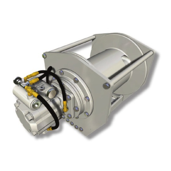
Hydraulic Hoist Series
INSTALLATION, MAINTENANCE,
Visit our Web site at www.paccarwinch.com for the most comprehensive collection of winch, hoist, and drive
information on the Internet. Most publications and specification sheets are available for downloading.
LIT2103 R6
July 2017
Printe d in USA
PD12C, PD15B, PD17A
AND SERVICE MANUAL
WRITE HOIST SERIAL NUMBER BELOW
First 2 numbers indicate
year manufactured
For serial number location see page 3
PD15B, PD17A
1
PD12C,
©2017 PACCAR Inc.
All rights reserved
Advertisement
Table of Contents

Related Manuals for Paccar Braden PD12C


Summary of Contents for Paccar Braden PD12C
- Page 1 Visit our Web site at www.paccarwinch.com for the most comprehensive collection of winch, hoist, and drive information on the Internet. Most publications and specification sheets are available for downloading. LIT2103 R6 July 2017 ©2017 PACCAR Inc. Printe d in USA All rights reserved...
-
Page 2: Table Of Contents
Table of Contents Foreword ..............................3 Explanation of Model Number .......................3 General Safety Recommendations ......................4 eory of Operation ..........................5 Hoist Installation ............................7 Recommended Fastener Torque ......................9 Wire and Braided Rope Installation ......................9 Two-speed Motor Case Drain Plumbing ....................10 Preventive Maintenance ........................10 Recommended Oil Change Information.....................11 Troubleshooting ............................12 Hoist Disassembly ..........................16... -
Page 3: Foreword
FOREWORD Read this entire publication and retain it for future reference. For inquiries regarding your BRADEN Planetary Hoist or this publication, please contact BRADEN Service Department at 918- 251-8511, Monday through Friday, 8:00 a.m. to 4:30 p.m. (CST). e minimum service intervals speci ed are for operating hours of the prime mover. e following service instructions have been prepared to provide assembly, disassembly and maintenance information for the BRADEN Model PD12C, PD15B and PD17A series hoist. -
Page 4: General Safety Recommendations
GENERAL SAFETY RECOMMENDATIONS Safety and informational callouts used in this manual include: CAUTION WARNING CAUTION – is emblem is used to warn against poten- WARNING – is emblem is used to warn against hazards tial or unsafe practices which COULD result in personal and unsafe practice which COULD result in severe per- injury and product or property damage if proper proce- sonal injury or death if proper procedures are not followed. -
Page 5: Eory Of Operation
THEORY OF OPERATION DESCRIPTION OF HOIST e hoist has four basic component parts: e static brake system has three operating compo- 1. Hoist base nents: 2. Hydraulic motor and brake valve 1. Spring Applied, Multiple Friction Disc Static Brake 3. Brake cylinder and motor support 2. - Page 6 Figure 3 the pressure to rise and the opening in the brake valve to en- large, speeding up the descent of the load. Decreasing this LOWERING 2 ow causes the pressure to lower and the opening in the brake Static Brake valve to decrease thus slowing the descent of the load.
-
Page 7: Hoist Installation
HOIST INSTALLATION e hoist should be mounted with the centerline of the VENT PLUG drum in a horizontal position. e mounting plane of the ABOVE CENTERLINE base may be rotated in any position around this center- line. CenterLine e vent plug must always be located above the horizontal centerline. - Page 8 HOIST ASSEMBLY WINCH ASSEMBLY W/BRAKE VALVE W/BRAKE VALVE & STATIC BRAKE & STATIC BRAKE BRAKE VALVE HOIST BRAKE BRAKE VALVE WINCH BRAKE CONTROL VALVE 2-SPEED SELECTOR VALVE CONTROL VALVE PUMP PUMP DO NOT use a control valve with any detents or latch- Oil having 150 to 330 SUS (30-60 cSt) viscosity at 104°F ing mechanism that would hold the control valve in an (40°C) and viscosity index of 100 or greater will give good...
-
Page 9: Recommended Fastener Torque
RECOMMENDED FASTENER TORQUE Higher or lower torques for special applications will be speci ed such as the use of spanner nuts, nuts on sha ends, jam nuts and where distortion of parts or gaskets is critical. Lubricated torque values based on use of SAE 30wt engine oil applied to threads and face of bolt or nut. Avoid using thread lubricants (such as anti-seize compound) as the applied torque may vary by 10 - 40%, depending upon the product used. -
Page 10: Two-Speed Motor Case Drain Plumbing
TWO-SPEED MOTOR CASE DRAIN PLUMBING Some hoists with two speed gear motors may have been in- stalled with the motor case drain connected to the drain port of the brake valve. is system may result in accelerated mo- tor sha seal wear and leakage. e following modi cation should be made to the motor hydraulic piping to prevent this type of seal damage. -
Page 11: Recommended Oil Change Information
Failure to properly warm up the hoist, particularly under low ambient temperature conditions, may result in tempo- rary brake slippage due to high back pressures attempting to release the brake, which could result in property dam- age, severe personal injury or death. 7. -
Page 12: Troubleshooting
RECOMMENDED GEAR OIL PREVAILING AMBIENT TEMPERATURE PREVAILING AMBIENT TEMPERATURE F -40 F -40 Use gear oil detailed in Range A Use gear oil detailed in Range B Use gear oil detailed in Range C C -40 C -40 SHADED TEMPERATURE RANGE IN THE CHART ABOVE NOT RECOMMENDED FOR SEVERE APPLICATIONS SUCH AS SUSTAINED SHADED TEMPERATURE RANGE IN THE CHART ABOVE NOT RECOMMENDED FOR SEVERE APPLICATIONS SUCH AS FAST DUTY CYCLES OR FREQUENT WINCHING. - Page 13 TROUBLE PROBABLE CAUSE REMEDY 3. Friction brake will not release as a 3. Disassemble brake to inspect brake e hoist will not lower the load or not result of damaged brake discs. discs. Check stack-up height as de- lower the load smoothly. scribed in “Motor Support-Brake Cylin- der Service”.
- Page 14 TROUBLE PROBABLE CAUSE REMEDY e hoist will not hoist the rated load. e hoist may be mounted on an un- 1. Mounting Surface: even or exible surface which causes a. If necessary, use shim stock to level distortion of the hoist base and binding hoist.
- Page 15 TROUBLE PROBABLE CAUSE REMEDY d. Hydraulic pump not operating ef- d. HYDRAULIC Pump: e hoist runs hot. ciently. d1. Same as REMEDY D2. d2. Prime mover low on horsepower or R.P.M. Tune/adjust prime mover. d3. Check suction line for damage. d4.
-
Page 16: Hoist Disassembly
HOIST DISASSEMBLY SERVICE PRECAUTIONS • Before any part is removed from the hoist, all service instructions should be read and understood. • Work in a clean, dust free area as cleanliness is of utmost importance when servicing hydraulic equipment. • Inspect all replacement parts, prior to installation, to detect any damage which might have occurred in shipment. - Page 17 10. Remove the seal and bearing from inside of closure. 11. Remove the primary sun gear and thrust washer from the primary planet carrier. 8. Remove the brake cylinder capscrews and install two (2) capscrews and a short piece of chain into the motor sup- port mounting bolt holes.
-
Page 18: List Of Components
16. Slide drum out of base onto a work bench and remove ring gear (machined into inside surface of drum) teeth seal and bearing from support end. for nicks, spalling or excessive wear. Replace if wear is greater than 0.015 in. (0.4 mm) when compared to un- oroughly clean and inspect drum and base. -
Page 19: Exploded-View Drawing
PD17A hoists use an internal retaining ring (item 16, not shown) to hold item 38 into the output planet carrier PD17A hoists use only 1 each of items 52 and 53 due to the shoulder on item 50. (shoulder is toward motor) Retaining ring (item 30) is... -
Page 20: Planet Carrier Service
PLANET CARRIER SERVICE OUTPUT PLANET CARRIER DISASSEMBLY 3. Now you can remove the planet sha s, bearings, spacer, thrust washers and gears. oroughly clean all parts and inspect for damage and wear. e bearing rollers should not exhibit any irregularities. If the rollers show any sign of spalling, corrosion, discoloration, material displace- ment or abnormal wear, the bearing should be replaced. - Page 21 PRIMARY PLANET CARRIER 1. To service the primary planet carrier, the steps are the same as for the output carrier except there is only one bearing for each gear and no bearing spacer. 2. Insert two (2) bearings and a bearing spacer into a gear with the spacer between the bearings.
-
Page 22: Motor Support - Brake Cylinder Service
MOTOR SUPPORT — BRAKE CYLINDER SERVICE NOTE: Starting mid-year 1996, BRADEN changed the steel brake separator discs from a splined tooth design to a lobed design. is required a change to the motor support and brake cylinder and the addition of a spring spacer. A hoist with the lobed discs can be identi ed by a machined groove on the outside diameter of the motor support. - Page 23 NOTE: It is a good practice to pre-lubricate the discs CAUTION in hydraulic oil prior to assembly. Failure to replace brake springs as a set may result in un- even brake application pressure and repeated brake spring failure. 4. Install the remaining brake spacer on top of the last steel brake disc.
- Page 24 6. Lubricate the brake piston seal and motor support sealing surface with petroleum jelly or hydraulic oil. Install new 8. Install pressure plate into brake cylinder followed by the piston seal to motor support, seal lip down. piston backup ring. e close- tting piston backup ring may be depressed slightly to one side to lodge the backup ring in the brake cylinder bore and temporarily hold the...
- Page 25 2. WHILE PRESSURE IS APPLIED AND THE BRAKE RE- LEASED, install the brake clutch assembly in the brake pack, short end of the inner race toward motor. Turn the clutch back and forth as you align the outer race splines with the brake disc splines.
-
Page 26: Brake Clutch Service
BRAKE CLUTCH SERVICE DISASSEMBLY 1. Remove the snap ring and sprag bushing retainer from 4. Next, slide the sprag clutch out, inspect the sprag clutch one end only. closely for abnormal wear, cracks, pitting or corrosion. Check small clips for breakage or bright spots; the signs NOTE: The brake clutch on PD17A hoists use a of excessive wear. - Page 27 6. Turn the assembly over with the snap ring down. Install the second retainer and snap ring. Make certain the snap ring is seated in the groove properly. 2. Turn the assembly over and install the sprag clutch in the bore of the outer race.
-
Page 28: Hoist Assembly
HOIST ASSEMBLY NOTE: PD15B HOISTS ONLY e drum closure will not t through the opening in the base. For hoists with a three piece base, rst assemble the bearing sup- port side plate (91) to the base plate (90). Go to step 1 and follow the assembly procedure. Install the motor end side plate and tie bar(s) a er installing the drum closure in step 10. - Page 29 CAUTION Be sure the vent plug is located above the horizontal cen- terline for the intended application. Oil leakage may occur if vent is positioned incorrectly. 4. Tighten the bearing support capscrews to the recom- mended torque. 8. Install the primary planet carrier, meshing the planet gears with the ring gear and the planet housing with the output sun gear.
- Page 30 11. Lubricate the pilot, oil seal and bearing surfaces of the brake cylinder and carefully install brake cylinder into base and drum. Locate the brake release port toward the lower rear corner of the base. Tighten brake cylinder capscrews to recommended torque. 14.
- Page 31 Measure the distance from the motor mounting surface to the inner brake race. With all components properly installed, this distance should be 11/16 in. (17.5 mm) to 3/4 in. (19.1 mm). If this distance is less than 9/16 in. (14.3 mm), the pri- mary spacer may be positioned as shown below and should be checked.
-
Page 32: Brake Valve Service
BRAKE VALVE SERVICE ITEM DESCRIPTION BRAKE VALVE HOUSING VALVE SPRING RETAINER SPRING RETAINER PLUG SPOOL SEC. A-A DAMPER PISTON O-RING DRAIN PORT CHECK VALVE POPPET PILOT ORIFICE CHECK VALVE SPRING SPOOL SPRING O-RING O-RING “BR” O-RING PORT BACK-UP RING BACK-UP RING STEEL BALL COMPRESSION SPRING ELBOW FITTING... - Page 33 5. Remove the damper piston from the spool. e piston ASSEMBLY will come out slowly, because of a partial vacuum formed as it is removed. Use extreme care to avoid damaging the 1. Install new O-rings on the plug and spring retainers. polished surfaces of the piston or spool.
-
Page 34: Reversing Direction Of Drum Rotation
REVERSING DIRECTION OF DRUM ROTATION Motor Case Drain Motor Case Drain Brake Brake Lowering Lowering Motor Motor Valve Valve Port Port Hoisting Hoisting Port Port Brake Release Brake Release Circuit Circuit M = Manifold Block In order to change the direction of rotation and brake operation, 2 components must be changed on the hoist. First, the motor must be made to rotate in the opposite direction. - Page 35 7. Before installing the brake clutch, be sure the inner race turns free in the opposite direction the drum will turn to haul-in wire rope. An easy way to check the rotation is to hold the outer race in one hand and rotate the inner race. Install the brake clutch with the short end of the inner race toward the motor.
-
Page 36: Pd17A Rotation Indication Proximity Sensor
PD17A ROTATION INDICATION PROXIMITY SENSOR Early PD17A models have a rotation indicator proximity sensor and hub between the motor and the hoist. If the sensor is removed or replaced, use the following procedure for adjustment and testing. Refer to the drawing below for item numbers. CAUTION If sensor hub is not correctly positioned with a lobe directly under the sensor port, proper adjustment may not be possible and severe damage to the sensor and internal hoist components may result. - Page 38 THIS PAGE INTENTIONALLY LEFT BLANK...
-
Page 39: Metric Conversion Table
METRIC CONVERSION TABLE English to Metric Metric to English LINEAR inches (in.) X 25.4 = millimeters (mm) millimeters (mm) X 0. 03937 = inches (in.) feet (ft.) X 0.3048 = meters (m) meters (m) X 3.281 = feet (ft.) miles (mi.) X 1.6093 = kilometers (km) kilometers (km) - Page 40 LIT2103 R6 ©2017 PACCAR Inc. July 2017 All rights reserved Printe d in USA...
Need help?
Do you have a question about the Braden PD12C and is the answer not in the manual?
Questions and answers