Table of Contents
Advertisement
Quick Links
English version of original German operating
instructions
EN
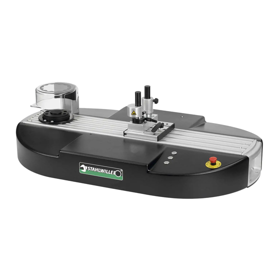
STAHLWILLE perfectControl
Motor-operated calibration and adjustment facility 7794-2
Read through these operating instructions carefully to ensure safe operation. Store these
instructions for further use.
Code number 91979873
Status: 06/2016
Advertisement
Table of Contents

Related Manuals for Stahlwille perfectControl 7794-2


Summary of Contents for Stahlwille perfectControl 7794-2
- Page 1 English version of original German operating instructions STAHLWILLE perfectControl Motor-operated calibration and adjustment facility 7794-2 Read through these operating instructions carefully to ensure safe operation. Store these instructions for further use. Code number 91979873 Status: 06/2016...
-
Page 2: Preface
If you do not understand any of the information in these operating instructions or information is missing, please contact STAHLWILLE Eduard Wille GmbH & Co. KG. -
Page 3: Table Of Contents
Contents Preface ................................ 2 Target group of these operating instructions ...................... 2 Introduction to the operating instructions ....................6 Availability ................................6 Supplements ............................... 6 Structural features .............................. 6 Explanation of the warning notices ........................6 Safety ................................7 Proper use, operating area ..........................7 Basic safety instructions ............................. - Page 4 Transportation ..............................14 Unpacking ................................. 15 Delivery ................................16 Scope of delivery ............................ 16 Check on acceptance by the recipient ....................16 Reporting and documenting transport damage ..................16 Packaging ............................... 17 Storage ................................17 Erection and mounting ..........................18 Installing extension 7791-1 ........................
- Page 5 Disposal ..............................39 Information on extension lengths ......................39 The correct tightening torque with unchanged extension lengths ..............39 The correct tightening torque with changed extension lengths ................ 39 Example 1: corrected setting value (one plug-in tool) ................40 Example 2: corrected setting value (plug-in tool and adapter) ............... 41 General information on calibration ......................
-
Page 6: Introduction To The Operating Instructions
If these operating instructions become lost or Explanation of the warning notices unusable, a new copy can be requested from STAHLWILLE Eduard Wille GmbH & Co. KG. The following categories of notices are contained in these operating instructions: If you have not yet registered the device, the... -
Page 7: Safety
Any other use is regarded as improper, particularly bending objects. • Never use the calibration and adjustment facility STAHLWILLE Eduard Wille GMBH & CO. KG with a damaged mains power cable, following a accepts no liability for damage arising as a result of malfunction or when the calibration and this. -
Page 8: Risk Of Injury Due To Crushing
Safety Warranty and liability Risk of injury due to crushing When operating the calibration and adjustment Warranty and liability claims in the event of personal facility, there is a risk of crushing the fingers at the injury and material damage are inadmissible if they following points: are attributable to one or more of the following causes:... -
Page 9: Duties When Handling This Calibration And Adjustment Facility
Safety Duties when handling this calibration Personnel training and adjustment facility • Only trained and familiarised personnel may work on the calibration and adjustment facility. Obligations on the part of the owner • The user's qualification requirements must be The owner is obliged only to allow the following defined by the customer. -
Page 10: Protective Facilities
Safety Protective facilities The calibration and adjustment facility is equipped with various protective facilities. Regularly check all available protective facilities as per the maintenance schedule. • In the event of an emergency, the calibration and adjustment facility is shut-down using an The position of the protective hood is polled using a emergency stop button. -
Page 11: Limitation Of The Movement Range
Safety Limitation of the movement range serves as a reference, for overloading. The transducer may be overloaded by a maximum of Limit switches are located in the calibration and 25 % of the maximum measuring range value. The adjustment facility's drive system. The limit switches software reports possible overloading via a warning limit the movement range. -
Page 12: Technical Description
Technical description Technical description Overview Explanation Explanation Protective cover Handle Bridge anti-trapping guard Emergency stop button Vertically adjustable rest for the Buttons calibration object Transducer flange Longitudinally adjustable carriage... -
Page 13: Technical Data
Technical description Technical data Max. permissible relative humidity 70 % (non-condensing) Ambient temperature in the laboratory From 18 °C to 28 °C (in accordance with EN ISO 6789:2003) IP system of protection IP 20 Operating temperature range From 10 °C to 40 °C Connection voltage 100 to 240 V AC Frequency... -
Page 14: Electrical Protection
Transportation, delivery, storage Electrical protection Identification The calibration and adjustment facility is equipped The calibration and adjustment facilities can be with one IEC power connector socket. This is fused identified via a serial number. The type plate is with two thermal glass fuses 6.3 A. If these fuses mounted next to the electrical connections on the trip due to overload, the control circuit for the entire calibration and adjustment facility. -
Page 15: Unpacking
Transportation, delivery, storage Unpacking WARNING Risk of injury when lifting the calibration and adjustment facility due to slipping out of the hand. Only lift the calibration and adjustment facility with the aid of a second person. To do this, use only the carrying handles which are provided on the calibration and adjustment facility. -
Page 16: Delivery
These are not contained in the scope of delivery. In the event of incorrect deliveries, notify us or the representative responsible for you. The following STAHLWILLE transducers can be used: Reporting and documenting transport damage • 7728-1 In the event of transportation damage, notify us or •... -
Page 17: Packaging
Transportation, delivery, storage Packaging Remove the existing packaging material. Remove the enclosed accessories. Make sure that the calibration and adjustment facility is not damaged. Storage Store the calibration and adjustment facility in packaged condition. Ensure the following storage conditions: • Relative humidity: 20-60 %, non-condensing •... -
Page 18: Erection And Mounting
Erection and mounting Erection and mounting Installing extension 7791-1 The calibration and adjustment facility must be CAUTION installed on a level surface with sufficient load- bearing capacity. It can be secured using the Risk of injury on assembly of the mounting holes in the handles at the sides. - Page 19 Installing extension 7791-1 Proceed as follows to mount extension 7791-1: Remove the two cheese head screws with hexagon socket, to which the handle on the right- hand side of the calibration and adjustment facility is secured. Insert one bolt into the intended opening on the left- and right-hand side of the extension.
- Page 20 Installing extension 7791-1 To secure the extension to the work surface, the mounting brackets (5) first have to be adjusted. Release the bolts for adjusting the mounting brackets. Lower the mounting brackets onto the work surface. Insert the extension with the two centring pins into the intended mountings on the calibration and adjustment facility.
-
Page 21: Connecting
PC connection Connect the PC here. Use only the 3.5 mm jack plug cable and the USB adapter from STAHLWILLE for this purpose. Calibration object connection Connect the electronic calibration objects of the... -
Page 22: Establishing Connections
Reference connection (transducer) (Laterally on the protective cover bracket): Connect the transducer here (1). Use only the intended STAHLWILLE connecting cable for transducers (helical cable) for this purpose. This cable must not transfer any forces to the transducer. Lateral forces can negatively influence the calibration results. -
Page 23: Operating The Calibration And Adjustment Facility
Operating the calibration and adjustment facility Operating the calibration and adjustment facility Alternatively, the optionally available manual operating terminal can be connected. This Controls enables you to carry out the same functions as with the controls available on the calibration and adjustment facility. -
Page 24: Control Functions
Operating the calibration and adjustment facility Control functions "Emergency stop" Press the emergency stop button to shut the calibration and adjustment facility button down in an emergency. The calibration and adjustment facility relieves itself automatically up to a torque of approx. 100-150 N m. Before continuing to operate the calibration and adjustment facility, the emergency stop button must be released and the fault acknowledged. -
Page 25: Using The Torkmaster 4 Programme
Using the TORKMASTER 4 programme Using the TORKMASTER 4 To start installation, confirm the query with programme "Execute". The language selection is displayed on the monitor. Installing the software Installing the TORKMASTER 4 programme The following system requirements must be met to install the TORKMASTER programme on your computer: •... - Page 26 Using the TORKMASTER 4 programme Read the licence agreement. Select the option "I accept the agreement". To continue installation, click onto "Continue". The "Select target folder" window is displayed. Enter the desired name for the start menu. To confirm the input, click onto "Continue". A summarisation of the settings which have been made is displayed.
-
Page 27: Manually Installing The Driver
• The message "No USB adapter found" is displayed in the programme user interface's status bar. Open the "www.stahlwille.de" site in the Internet. If you are already a registered customer, log in under "My account". If you are not yet a registered customer, you can create an account under "My account". -
Page 28: The Main Menu Controls
Using the TORKMASTER 4 programme The main menu controls The main menu contains the following displays and controls:... - Page 29 Using the TORKMASTER 4 programme Number Designation Serial number of the calibration facility and selection field for manual selection of the calibration facility Input or selection of the calibration object ("Calibration object") Selection of the calibration method Result of the current measurement Numerical display of the current measured value Bar display of the measured value in the permissible measuring range Graphical portrayal of the current measured value...
- Page 30 Using the TORKMASTER 4 programme Selection of the calibration method One of the following test methods can be selected: • Quick test: The tool is tested without creating a standard- conforming log. • Test and adjustment: A tool can be tested and adjusted in the case of deviating values.
-
Page 31: Operating The Torkmaster 4 Programme
Using the TORKMASTER 4 programme Buttons for functions These buttons can be used to execute the following functions: Number Function Completely repeat the last calibration. Delete the result of the last measurement. To delete several results, this step can be repeated. Calibration is then continued and all deleted measurements are repeated. -
Page 32: Preparing For Operation
Preparing for operation Preparing for operation Preparing the PC ATTENTION CAUTION Malfunctions due to non-installed Crushing of the fingers due to the software. carriage tilting as a result of soiled guide rails. Only connect the USB adapter to the PC once the TORKMASTER has Make sure that the guide rails are been installed. -
Page 33: Calibrating And Adjusting Torque Wrenches
Calibrating and adjusting torque wrenches Calibrating and adjusting Set-up mode torque wrenches After switching on or after pressing the stop button at the end of a calibration process, the calibration and adjustment facility is in set-up mode. CAUTION The yellow LED in the start button lights up. Risk of injury due to the torque wrench To turn the transducer counter-clockwise, press breaking. -
Page 34: Testing And Adjusting
The calibration data are automatically read-in from Observe the function lengths in the Annex for the database. STAHLWILLE torque wrenches. Set the desired calibration value on the calibration Lock the longitudinal carriage using the lever on object. -
Page 35: Measuring Calibration
Observe the function lengths in the Annex for dimension of less than 4 mm. STAHLWILLE torque wrenches. Tighten the clamp screw hand-tight. Lock the longitudinal carriage using the lever on Close the protective cover. -
Page 36: Maintenance
Maintenance Maintenance • Prevent the ingress of soap solution into bearings, seals and electrical systems. Maintenance work is exclusively performed on the • Clean corroded areas and, if permissible, coat outside of the calibration and adjustment facility. with paint, grease or oil. Proceed as follows before carrying out maintenance •... -
Page 37: Lubricating
Maintenance Check whether a glass tube fuse is defective. Replace a defective glass tube fuse with a functioning fuse of the same type. Insert the fuse holder together with the glass tube fuses. Lubricating The calibration and adjustment facility is equipped with a central lubrication system. -
Page 38: Maintenance Schedule For The Mechanical System
Lubricate the lubricating system adjustment facility must nipple with two pumps of be lubricated every three the grease gun. months. Further service and maintenance work on the calibration and adjustment facility may only be carried out by specialist personnel from STAHLWILLE. -
Page 39: Disposal
Disposal Disposal Information on extension lengths Dispose of the calibration and adjustment facility via a certified specialist disposal company. Observe and comply with the applicable regulations. If in The correct tightening torque with unchanged extension lengths doubt, contact your municipal or local administration. -
Page 40: Example 1: Corrected Setting Value (One Plug-In Tool)
Function length (see torque wrench dimension tables) =corrected function length L – +S (or ∑S) Extension length of the STAHLWILLE plug-in tools or special tools (see plug- in tool dimension tables) Standard extension length (see torque wrench dimension tables) ∑S... -
Page 41: Example 2: Corrected Setting Value (Plug-In Tool And Adapter)
Information on extension lengths How to find the data in the catalogue: Example 2: corrected setting value (plug-in tool and adapter) Torque wrench No. 730N/10 combined with square plug-in tool No. 734/5 and adapter No. 447 AF 10 mm. Desired bolt tightening torque M =25 N‧m Torque wrench =336 mm,... -
Page 42: General Information On Calibration
General information on calibration General information on The dimension SF is the standard extension length calibration of the plug-in tools which are used. The dimension LF is the lever arm to be used If no internal test equipment monitoring procedures during calibration, measured from the centre of the are available, the calibration interval defined in the bolt head (centre of the transducer). -
Page 43: Torque Wrench Dimension Tables
Torque wrench dimension tables Torque wrench dimension tables Type 71 Type 714 Model SF [mm] LF [mm] Model SF [mm] LF [mm] 17.5 1050 17.5 aR/80 – 1060 17.5 17.5 Types 712/713 17.5 1158 1343 17.5 Model SF [mm] LF [mm] 17.5 17.5 712/6... - Page 44 Torque wrench dimension tables Type 720NF Type 730 Model SF [mm] LF [mm] Model SF [mm] LF [mm] – – Type 721 Type 730 D Model SF [mm] LF [mm] Model SF [mm] LF [mm] – 17.5 426.5 – – –...
- Page 45 Torque wrench dimension tables Type 730 Type 730N Model SF [mm] LF [mm] Model SF [mm] LF [mm] 17.5 17.5 17.5 17.5 280.5 a/2-1 17.5 17.5 17.5 a/40 17.5 425.5 17.5 564.5 17.5 1167 1352 17.5 II/65 17.5 280.5 17.5 a/10 17.5 a/10...
- Page 46 Torque wrench dimension tables Type 730 NR Model SF [mm] LF [mm] – 280.5 10FK – 336.5 20FK – 40FK – 564.5 65FK-HD – 5QR FK – 100QR FK – 346.5 200QR FK – 438.5 Type 755 Model SF [mm] LF [mm] 17.5 17.5...
-
Page 47: Subsequent Additions To The Operating Instructions
Subsequent additions to the operating instructions Subsequent additions to the destroyed. The additions supplied for the manual operating instructions must be confirmed at this point to be able to check that they are completely up to date and that all It sometimes occurs that manuals have to be additions have been carried out: supplemented, modified or updated. -
Page 48: Eu Declaration Of Conformity
EU declaration of conformity EU declaration of conformity... - Page 49 Manufacturer: STAHLWILLE Eduard Wille GmbH & Co. KG (P.O. Box) Postfach 12 01 03 — 42331 Wuppertal Lindenallee 27 — 42349 Wuppertal Germany Tel.: + 49 202 4791-0 Fax: + 49 202 4791-200 E-mail: info@stahlwille.de Internet: www.stahlwille.de...
Need help?
Do you have a question about the perfectControl 7794-2 and is the answer not in the manual?
Questions and answers