
Related Manuals for Matt:e SP-EVCP-T


Summary of Contents for Matt:e SP-EVCP-T
- Page 1 Single Phase Electric Vehicle Charger Protection Units SP-EVCP-T(C) SP-EVCP-R(C) SP-EVCP-M(C) SP-EVCP-B(C) IP-EVCP-T(C) IP-EVCP-R(C) IP-EVCP-M(C) Installation Manual V1.5 Aug 2020...
-
Page 2: Table Of Contents
Single Phase EV Charger Protection unit Contents Product Description Warning Notice Safety Advice Introduction Dimensions & Mounting the unit Electrical Connections Operating Instructions Status Indicator Specifications Warranty Declaration of Conformity PRODUCT ADVISORY NOTICE This product must be installed by a competent person in accordance with the IET Wiring Regulations, BS7671 (18 Edition or later) and current Building Regulations. -
Page 3: Product Description
PME supplies are feeding Electric Vehicle Chargers. They should NOT be used on premises with 3 phase supplies This manual covers the SP-EVCP-T(C), SP-EVCP-R(C), SP-EVCP-M(C), SP-EVCP-B(C), IP-EVCP-T(C), IP-EVCP-R(C), & IP-EVCP-M(C) models manufactured after April 2020 The units are not intended for any purpose other than that defined within this document. -
Page 4: Introduction
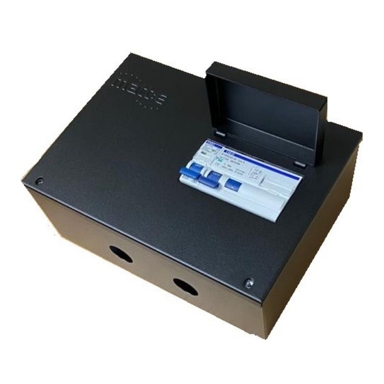
Single Phase EV Charger Protection unit Introduction matt:e range of Single Phase Electric Vehicle Charger Protection units are designed to protect Electric Vehicle Charging equipment when installed onto single-phase PME infrastructures . All units incorporate an electronic detection circuit and 3 pole contactor. The T version has three terminals on the incoming side of the unit. -
Page 5: Dimensions & Mounting The Unit
Single Phase EV Charger Protection unit P a g e... - Page 6 Single Phase EV Charger Protection unit P a g e...
- Page 7 Single Phase EV Charger Protection unit P a g e...
-
Page 8: Electrical Connections
Single Phase EV Charger Protection unit Electrical Connections The user wiring connections are indicated in the diagrams below. Connect the supply cable from the distribution board directly to the ‘Incoming Supply’ terminals. Connect the outgoing cable to the contactor L, E & N terminals. If required, connect the CT to the 3 pin connector on the PCB Check ALL power and earth connections before switching on. - Page 9 Single Phase EV Charger Protection unit Connect the supply cable from the distribution board directly to the MCB ‘Incoming Supply’ terminals. Connect the outgoing cable to the contactor L, E & N terminals. If required, connect the CT to the 3 pin connector on the PCB Check ALL power and earth connections before switching on.
- Page 10 Single Phase EV Charger Protection unit Connect the supply cable from the distribution board (or meter tails) directly to the RCBO ‘Incoming Supply’ terminals. Connect the outgoing cable to the contactor L, E & N terminals. If required, connect the CT to the 3 pin connector on the PCB Check ALL power and earth connections before switching on.
- Page 11 Single Phase EV Charger Protection unit Connect the supply cable from the distribution board (or meter tails) directly to the MCB/RCCD ‘Incoming Supply’ terminals. Connect the outgoing cable to the contactor L, E & N terminals. If required, connect the CT to the 3 pin connector on the PCB Check ALL power and earth connections before switching on.
- Page 12 Single Phase EV Charger Protection unit Connect the supply cable from the distribution board (or meter tails) directly to the RCBO ‘Incoming Supply’ terminals. Connect the outgoing cable to the contactor L, E & N terminals. If required, connect the CT to the 3 pin connector on the PCB Check ALL power and earth connections before switching on.
- Page 13 Single Phase EV Charger Protection unit Connection details for CT versions 13 | P a g e...
-
Page 14: Operating Instructions
Single Phase EV Charger Protection unit Operating Instructions With the supply switched on the electronic control circuit in unit will continuously monitor the incoming supply voltage. If the incoming supply is within limits, approximately 5 seconds after switching on the contactor will energise and connect the load to the incoming supply and the CPC. -
Page 15: Status Indicator
Single Phase EV Charger Protection unit Status Indicator A dual colour (Red / Green) LED gives a visual indication of the real time status of the unit. LED flash codes 1 red flash (major) followed by 2 green flashes (minor), this Version info Software Ver. -
Page 16: Specifications
The SP-EVCP units are guaranteed for a period of 3 years from the date of manufacture. This warranty is limited to the replacement of faulty components only. t: 01543 227290 e: info@matt-e.co.uk w: www.matt-e.co.uk matt:e Ltd, Unit 5, Common Barn Farm, Tamworth Road, Lichfield WS14 9PX 16 | P a g e... -
Page 17: Declaration Of Conformity
EN61008-1 Residual current operated circuit-breakers without integral overcurrent EN 60898-1:2019 Electrical accessories - Circuit-breakers for overcurrent protection for household and similar installations - Part 1: Circuit-breakers for a.c. operation Signed for and on behalf of: matt:e Ltd Place of issue Date...
Need help?
Do you have a question about the SP-EVCP-T and is the answer not in the manual?
Questions and answers