REMIS REMItop Vario II Replacement Instruction
Multifunction roof window for motor homes and caravans
Hide thumbs
Also See for REMItop Vario II:
- Replacing instructions (8 pages) ,
- Assembly instructions manual (32 pages) ,
- Assembly instructions manual (11 pages)
Advertisement
Available languages
Available languages
Quick Links
D
REMItop Vario II
Multifunktionales Dachfenster
für Motorcaravans und Caravans
US/GB
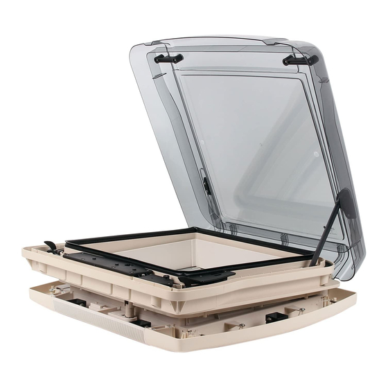
Multifunction roof window
for motor homes and caravans
F
Lanterneau multifonctionnel
pour camping-cars et caravanes
Anleitung zum Austausch der Aufstellmechanik, der Niederhalter und der
Ratschkurbel
Instruction for replacing the lifting mechanism, the holding-down clamp and the
ratchet crank
Instruction de remplacement du mécanisme d'ouverture, du serre-fl an et de la
manivelle débrayable
1/28
Advertisement

Related Manuals for REMIS REMItop Vario II


Summary of Contents for REMIS REMItop Vario II
- Page 1 REMItop Vario II Multifunktionales Dachfenster für Motorcaravans und Caravans US/GB Multifunction roof window for motor homes and caravans Lanterneau multifonctionnel pour camping-cars et caravanes Anleitung zum Austausch der Aufstellmechanik, der Niederhalter und der Ratschkurbel Instruction for replacing the lifting mechanism, the holding-down clamp and the ratchet crank Instruction de remplacement du mécanisme d’ouverture, du serre-fl...
- Page 2 Angaben zur Montage Schritt 1: (Lieferumfang prüfen) Lieferumfang: Im Lieferumfang fi nden Sie folgendes Zubehör: - Für die Haube in 400x400 (B1+B3+B4): 1x Haubenbolzen 1x Aufsteller rechts vomontiert 1x Welle Schneckenzahnrad 1x Zahnrad Schneckenwelle 1x Gegendrucklager 3x Halter Schutzschlauch 1x Doppelclip 1x Sicherungsscheibe 3,2x0,7 18x Schraube 3,5x16 1x Niederhalter rechts...
- Page 3 Schritt 2: (Demontage des vorhandenen Aufstellers) B5-B7: Den Innenrahmen nacheinander an den gezeigten Ecken vorsichtig abziehen (Die Abbildung zeigt die Demontage an einem Rahmen der Größe 400x400. Die Demontage des Rahmens bei den Größen 700x500 und 900x600 ist ähnlich, diese verfügen lediglich über mehr Fixierungspunkte).
- Page 4 B10-B12: Lösen Sie alle Schrauben vom Getriebedeckel und den Befestigungsstellen der Schläuche (Darstellung der Gr. 700x500, Gr. 400x400 ist leicht abweichend). Getriebedeckel B13: Entfernen Sie anschließend alle Befestigungsschrauben der Aufsteller. Bei der Größe 400x400 ist dieser nur auf der rechten Seite vorhanden. 4/28...
- Page 5 Schritt 3: (Montage des neuen Aufstellers) B14: Setzen Sie den Aufsteller (400 x 400) bzw. beide Aufsteller in die entsprechende Aufnahme der zuvor entfernten Aufsteller. Achten Sie darauf, dass der Aufstellerhebel bei den beiden großen Größen vollständig nach hinten geschoben ist, damit diese später synchron laufen. B15: Montieren Sie die neuen Haubenbolzen, indem Sie die harpunenartige Spitze von Innen durch die Aufnahme der...
- Page 6 B19: Drücken Sie den Getriebedeckel vorsichtig in die gezeigte Position. Achten Sie darauf, dass die Welle durch die markierte Bohrung geschoben wird. B20: Drücken Sie die Schläuche vorsichtig in die im Bild gezeigte Nut (Darstellung der Gr. 400x400). Achten Sie darauf, dass sich die Schlauchbefestigungen an den vorgesehenen Verschraubungspunkten positionieren.
- Page 7 B22 (Wiederanbringen des Sicherungsrings (befi ndet sich am Getriebe)): Drücken Sie zuletzt den Sicherungsring beispielsweise mit einem Schraubendreher an die Welle. B23: Zur Montage des Niederhalters tauschen Sie die weiße Unterlegscheibe gegen die im Lieferumfang enthaltene Di- stanzhülse Ø8x6mm aus. Achten Sie darauf, dass die Zug- feder vorhanden bleiben.
- Page 8 B31: Der Innenrahmen muß sich im ausgebauten Zustand befi n- den. Legen sie den Rahmen so ab, dass Sie an den Siche- rungsring kommen. Entfernen Sie als nächstes den Sicherungsring mit der See- gerringzange von der Handkurbel. Drücken Sie jetzt die Kurbel nach unten durch die Öffnung heraus.
- Page 9 This requirement applies particular- ly to safety instructions, which are specially marked in these operating instructions. The copyright to the operating instructions is reserved by REMIS GmbH. These ope- rating instructions are only intended for the operator and the operator’s personnel.
- Page 10 Installation instructions Step 1: (Check delivery scope) US/GB Delivery scope: The scope of delivery includes the following accessories: - For the roofl ight in 400x400 (B1+B3+B4): 1x Hood bolt 1x Put-up hinge right preassembled 1x Worm toothed wheel 1x Worm toothed gearwheel 1x Counterpressure bearing 3x Protective tube holder 1x Double clip...
- Page 11 Step 2: (Disassembly of the existing put-up hinges) B5-B7: Remove the inside frame by pulling it carefully in the sequence shown on the left (the picture shows the US/GB removal of a frame in the dimension 400x400. The only difference in the removal of frames in dimension 700x500 or 900x600 is that they have more fi...
- Page 12 B10-B12: Release all of the screws from the gearbox cover and the fi tting positions on the hoses (representation of sizes 700x500, 400x400 deviates slightly). US/GB Gearbox B13: Remove all of the fi xing screws from the put-up hinges. For the dimension 400x400 this put-up hinge is only on one side.
- Page 13 Step 3: (Assembly of the new put-up hinges) B14: Place the put-up hinge(s) into the NOTICE!!! holding fi xture that the existing put- US/GB up hinge was removed from. For the dimensions 700x500 and 900x600 make sure that the arms of the put-up hinges are pushed right back so that these will later move in a synchronised manner.
- Page 14 US/GB B19: Push the gearbox cover carefully into the position shown. Ensure that the shaft is pushed through the marked drill hole. B20: Push the hoses carefully into the groove shown in the image (400x400 size represented). Ensure that the hose fi...
- Page 15 B22 (Replacement of the safety ring (to be found on the mecanism box)): Finally, push the safety ring onto the shaft, for example using a screwdriver. US/GB B23: For the assembly of the holding-down clamp exchange the white washers against the distance sleeves Ø8x6mm pro- vided in the delivery scope.
- Page 16 US/GB B31: The inside frame must be removed fi rst. Put the frame down so that you can access the retaining ring. Now remove the retaining ring from the hand crank with the Seeger circlip ring pliers. Now press the crank down- wards through the opening.
- Page 17 Indications de montage Étape 1: (Vérifi er le contenu) Contenu de livraison: Les accessoires suivants font partie de la livraison: - Pour lanterneau dimension 400x400 (B1+B3+B4): 1x Cheville de lanterneau 1x Bras de compas droit prémontée 1x Arbres roue de vis sans fi n 1x Roue dentée arbre à...
- Page 18 Étape 2: (Demontage bras de compas existants) B5-B7: Tirer avec precaution et successivement les points du cadre intérieur dans l´ordre indiqué à gauche (L´image montre le démontage d´un cadre intérieur de dimension 400x400. Le démontage du cadre intérieur des dimensions 700x500 ou 900x600 est identique, sauf qu´il y a plus de points de fi...
- Page 19 B10-B12: Dévissez toutes les vis du couvercle du mécanisme et des points de fi xation des tuyaux (représentation des dim. 700x500, dim. 400x400 est légèrement divergente). Couvercle du mécanisme B13: Retirer toutes les vis de fi xation des bras de compas. Pour la dimension 400x400 il n´y a qu´un seul bras de compas à...
- Page 20 Étape 3: (Montage des nouveaux bras de compas) B14: Positionner les nouveaux bras de compas dans l´emplacement duquel vous avez ôté les pièces existantes. Faites attention de repousser les bras de compas au fond jusqu´ en fi n de course afi n d´assurer leur fonctionnement synchronisé...
- Page 21 B19: Enfoncez le couvercle du mécanisme avec précaution dans la position indiquée. Veillez à ce que l’arbre soit poussé à travers la perforation marquée. B20: Enfoncez les tuyaux dans l’encoche indiquée sur la photo avec précaution (représentation de la dim. 400x400). Veil- lez à...
- Page 22 B22 (Repositionnement du circlips (accessible sur le véhicule au niveau du mécanisme d’ouverture)): Puis enfoncez enfi n l’anneau de fi xation, par exemple à l’aide d’un tournevis, dans l’arbre. B23: Pour installer les serre-fl ans noirs, échangez les rondelles blanches contre les douilles de distance Ø8x6mm qui sont fournies ci-jointes.
- Page 23 B31: Le cadre intérieur doit toujours être démonté. Posez le cadre de facon à accéder à la bague d´arrêt. Puis enle- vez cette bague à l´aide d´une pince à couronne. Retirez maintenant la manivelle par l´ouverture. Installez la nou- velle manivelle fournie dans l´ordre inverse du démontage de l´ancienne.
- Page 24 Cette documentation, y compris tous ses éléments, est protégée par les droits d’auteur. Toute utilisation ou modifi cation situées en dehors des limites strictes de la loi sur les droits d’auteur sont interdites sans l’autorisation de REMIS et constituent un acte délictueux.
Need help?
Do you have a question about the REMItop Vario II and is the answer not in the manual?
Questions and answers