Advertisement
®
This publication contains the installation, operation and
maintenance instructions for standard units of the CA, CF,
and CP: Centrifugal Blowers.
• CA/CF SWSI
• CA-4 SWSI
• CA DWDI
• CA-4 DWDI
• CPFD
Carefully read this publication and any
supplemental documents prior to any
installation or maintenance procedure.
Loren Cook catalogs, CA/CF and CP, provide additional
information describing the equipment, fan performance,
available accessories and specification data.
For additional safety information, refer to AMCA Publi-
cation 410-96, Safety Practices for Users and Installers of
Industrial and Commercial Fans.
All of the publications listed above can be obtained from:
• lorencook.com
• info@lorencook.com
• 417-869-6474 ext. 166
For information and instructions on special equipment,
contact Loren Cook Company at 417-869-6474.
Receiving and Inspection
Carefully inspect the fan and accessories for any dam-
age and shortage immediately upon receipt of the fan.
• Turn wheel by hand to ensure it turns freely and does not
bind
• Inspect dampers (if supplied) for free operation of all mov-
ing parts
• Record on the Delivery Receipt any visible sign of damage
Handling
Lift the fan by the base or lifting eyes.
NOTICE! Never lift by the shaft, motor or housing.
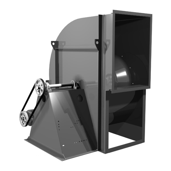
CA SWSI Shown
CA/CF/CP IO&M
INSTALLATION, OPERATION AND MAINTENANCE MANUAL
• CPFB
• CAF-DW
• CPA/CPA-A/CPS/
CPS-A/CPV
Rotating Parts & Electrical Shock Hazard:
Fans should be installed and serviced by qualified person-
nel only.
Disconnect electric power before working on unit (prior to
removal of guards or entry into access doors).
Follow proper lockout/tagout procedures to ensure the unit
cannot be energized while being installed or serviced.
A disconnect switch should be placed near the fan in order
that the power can be swiftly cut off, in case of an emer-
gency and in order that maintenance personnel are pro-
vided complete control of the power source.
Grounding is required. All field-installed wiring must be
completed by qualified personnel. All field installed wiring
must comply with National Electric Code (NFPA 70) and all
applicable local codes. Ensure the power supply (voltage,
frequency and current carrying capacity of wires) is in ac-
cordance with the motor nameplate.
Fans and blowers create pressure at the discharge and
vacuum at the inlet. This may cause objects to get pulled
into the unit and objects to be propelled rapidly from the
discharge. The discharge should always be directed in a
safe direction and inlets should not be left unguarded. Any
object pulled into the inlet will become a projectile capable
of causing serious injury or death.
When air is allowed to move through a non-powered fan,
the impeller can rotate, which is referred to as windmill-
ing. Windmilling will cause hazardous conditions due to
unexpected rotation of components. Impellers should be
blocked in position or air passages blocked to prevent draft
when working on fans.
Friction and power loss inside rotating components will
cause them to be a potential burn hazard. All components
should be approached with caution and/or allowed to cool
before contacting them for maintenance.
Under certain lighting conditions, rotating components
may appear stationary. Components should be verified to
be stationary in a safe manner, before they come into con-
tact with personnel, tools or clothing.
Failure to follow these instructions could result in death or
serious injury.
The attachment of roof mounted fans to the roof curb as
well as the attachment of roof curbs to the building struc-
ture must exceed the structural requirements based on the
environmental loading derived from the applicable build-
ing code for the site. The local code official may require
variations from the recognized code based on local data.
The licensed engineer of record will be responsible for pre-
scribing the correct attachment based on construction ma-
terials, code requirements and environmental effects spe-
cific to the installation.
1
CA/CF/CP
Centrifugal Blower
B51181-002
Advertisement
Table of Contents

Related Manuals for COOK CA Series


Summary of Contents for COOK CA Series
- Page 1 A disconnect switch should be placed near the fan in order that the power can be swiftly cut off, in case of an emer- Loren Cook catalogs, CA/CF and CP, provide additional gency and in order that maintenance personnel are pro- information describing the equipment, fan performance, vided complete control of the power source.
- Page 2 Storage Ceiling Mounted Spring and Rubber-in-Shear (RIS) Isolators If the fan is stored for any length of time prior to installa- tion, completely fill the bearings with grease or moisture- NOTICE! Under no circumstance is the fan to be inhibiting oil (refer to Lubrication, pages 6–7). Rotate the mounted inverted and hung by its base angles.
- Page 3 3. Position isolators under fan (or isolation base/rails) Discharge Duct Turns and secure bolts. Make sure that duct turns located near the fan discharge 4. Remove blocks and allow fan to rest on floor. Isolators curve in the direction of the fan’s rotation. must be installed on a level surface (leveling should Correct Incorrect...
-
Page 4: Wiring Installation
Belt and Pulley Installation CAF-DW WHEEL SHROUD Size Overlap Belt tension is determined by the sound the belts make when INLET INLET 1/8” the fan is first started. Belts will produce a loud squeal which 135–165 5/32” dissipates after the fan is operating at full capacity. If the belt 1/4”... - Page 5 Recommended Torque for Setscrews/Bolts (IN-LB) Single Speed, Single Phase, Dual Voltage Setscrews Hold Down Bolts Ground A Ground A Recommended Key Hex Recommended Torque Size Across Size Torque Flats Min. Max. Link A Link A 5/64” 3/8”-16 and B Link B Line Line 3/32”...
-
Page 6: Maintenance
Frequency Drive (VFD) must be VFD compatible. Motors • Inspect for cleanliness. Clean exterior surfaces only. Removing that are not supplied by Loren Cook Company should have dust and grease on motor housing assures proper motor cool- the recommendation of the motor manufacturer for use ing. - Page 7 Should the motor prove defective within a one-year pe- 0.87 not available above 300°. 0.81 riod, contact your local Loren Cook representative or your 0.75 nearest authorized electric motor service representative. For elevated airstream temperatures, the maximum fan speed limits must be derated by the factors above.
-
Page 8: Troubleshooting
Place the bearings into position making sure they are not 17. Adjust the belt tension. on a worn section of the shaft. Tapping the inner ring face 18. Test run and retighten all setscrews and bolts; trim bal- with a soft driver may be required. ance as necessary (.0785 in/sec max.). -
Page 9: Parts List
Parts List CA,CF SWSI Arrangement 1 Drive Side View Discharge Side View Inlet Side View CA, CF SWSI Arrangement 3 Discharge Side View CA, CF SWSI Arrangement 9 Part No. Arr. 1 Arr. 3 Arr. 9 Motor Slide Base Motor Motor Sheave Belt Set Fan Sheave... - Page 10 CA DWDI Drive Side View Free Side View Discharge Side View CA-4 DWDI Drive Side View Free Side View Discharge Side View CAF-DWDI Drive Side View Free Side View Discharge Side View Part No. CA DWDI CAF-DW CA-4 DWDI Motor Slide Base Motor Motor Sheave Belt Set...
- Page 11 CPFB 10 15 CPFB, CPA, CPA-A, CPS, Part No. CPS-A, CPV Arr. 4 Motor Plate Motor Motor Sheave Belt Set Fan Sheave Drive Side View Discharge Side View Inlet Side View Housing Shaft CPA, CPA-A, CPS, CPS-A CPV Outboard Bearing Inboard Bearing 10 15 Wheel...
-
Page 12: Limited Warranty
Cook Company, General Offices, 2015 East Dale Street, Springfield, Missouri 65803-4637, explaining in writing, in detail, your complaint and referring to the specific model and serial numbers of your fan. Upon receipt by Loren Cook Company of your written complaint, you will be notified, within thirty (30) days of our receipt of your complaint, in writing, as to the manner in which your claim will be handled.
Need help?
Do you have a question about the CA Series and is the answer not in the manual?
Questions and answers