Canon imageRUNNER ADVANCE C5051 Series Service Manual
Hide thumbs
Also See for imageRUNNER ADVANCE C5051 Series:
- Getting started (252 pages) ,
- Maintenance manual (160 pages) ,
- User manual (152 pages)
Advertisement
Quick Links
September 13, 2017
Revision 15
imageRUNNER ADVANCE
C5051/C5045/C5035/C5030 Series
Service Manual
Product Overvew
Technology
Periodical Service
Parts Replacement and Cleaning
Adjustment
Troubleshooting
Error Code
Service Mode
Installation
Appendix
1
2
3
4
5
6
7
8
9
Advertisement

Related Manuals for Canon imageRUNNER ADVANCE C5051 Series


Summary of Contents for Canon imageRUNNER ADVANCE C5051 Series
- Page 1 September 13, 2017 Revision 15 imageRUNNER ADVANCE C5051/C5045/C5035/C5030 Series Service Manual Product Overvew Technology Periodical Service Parts Replacement and Cleaning Adjustment Troubleshooting Error Code Service Mode Installation Appendix...
- Page 2 This manual is copyrighted with all rights reserved. Under the copyright laws, this manual may changes in the contents of this manual over a long or short period, Canon will issue a new not be copied, reproduced or translated into another language, in whole or in part, without the edition of this manual.
- Page 3 Explanation of Symbols The following rules apply throughout this Service Manual: The following symbols are used throughout this Service Manual. Each chapter contains sections explaining the purpose of specific functions and the Symbols Explanation Symbols Explanation relationship between electrical and mechanical systems with reference to the timing of operation.
- Page 4 Contents Safety Precautions Technology Laser Safety --------------------------------------------------------------------0-2 Basic Configuration -----------------------------------------------------------2-2 Handling of Laser System --------------------------------------------------0-2 Functional Configuration --------------------------------------------------------- 2-2 Turn power switch ON -------------------------------------------------------0-3 Controller System ------------------------------------------------------------2-5 Safety of Toner -----------------------------------------------------------------0-3 Overview ----------------------------------------------------------------------------- 2-5 About Toner ------------------------------------------------------------------------- 0-3 Controls ----------------------------------------------------------------------------- 2-11 Toner on Clothing or Skin -------------------------------------------------------- 0-3 Service Operations ---------------------------------------------------------------2-29 Notes When Handling a Lithium Battery --------------------------------0-3...
- Page 5 Setting the method to login to SMS ---------------------------------------- 2-126 Limitations and Cautions ------------------------------------------------------ 2-203 Checking MEAP Application Management Page ----------------------- 2-129 Preparation ----------------------------------------------------------------------- 2-204 Starting and Stopping a MEAP Application ------------------------------- 2-130 System Management Operations ------------------------------------------- 2-212 Checking the Platform Information ----------------------------------------- 2-130 Maintenance --------------------------------------------------------------------- 2-219 MEAP Specifications ----------------------------------------------------------- 2-131 FAQ --------------------------------------------------------------------------------- 2-220...
- Page 6 Removing the Toner Filter ------------------------------------------------------4-86 Removing the Pressure Roller and Pressure Roller Bearing -------- 4-146 Removing the ITB Unit ----------------------------------------------------------4-86 Pickup Feed System ----------------------------------------------------- 4-148 Cleaning the Patch Sensor -----------------------------------------------------4-89 Cleaning the Secondary Transfer Guide ---------------------------------- 4-148 Remove the Patch Sensor (front,center,rear)------------------------------4-89 Cleaning the Feed Contact Point Guide ---------------------------------- 4-148 Removing the ITB Cleaning Unit ----------------------------------------------4-91 Cleaning the Registration Roller -------------------------------------------- 4-149...
- Page 7 Adjustment Flow C: Main Controller Analysis Flow --------------------------------------6-25 Flow D: All-night Power Supply (3.3V) System Flow---------------------6-27 Main Controller ----------------------------------------------------------------5-2 Flow E: 12V Power Supply System Flow -----------------------------------6-30 HDD ----------------------------------------------------------------------------------- 5-2 Flow F: Connector Disconnection Flow -------------------------------------6-33 Main controller PCB 1 ------------------------------------------------------------ 5-2 Reference: Activation conditions of the Control Panel Backlight -----6-34 Main controller PCB 2 ------------------------------------------------------------ 5-3 Flow G: Execution Flow of Startup System Failure Diagnosis --------6-35...
- Page 8 Installation Color Image Reader Unit-B2 ------------------------------------------------- 7-118 Staple Finisher-C1 / Booklet Finisher-C1 --------------------------------- 7-119 How to Check this Installation Procedure -------------------------------9-2 Inner Finisher-A1 ---------------------------------------------------------------- 7-121 When Using the Parts Included in the Package---------------------------- 9-2 Alarm Code ----------------------------------------------------------------- 7-122 Symbols in the Illustration ------------------------------------------------------- 9-2 Alarm Code ----------------------------------------------------------------------- 7-122 Things to do Before Installation -------------------------------------------9-2 Selecting an Installing Location ------------------------------------------------ 9-2...
- Page 9 Card Reader-C1/Copy Card Reader-F1 ------------------------------ 9-94 Checking after the installation -------------------------------------------------9-51 Cassette Heater Unit ------------------------------------------------------- 9-52 Points to Note at Installation ---------------------------------------------------9-94 Checking the Contents (ASIA only) ------------------------------------------9-52 Checking the Contents ----------------------------------------------------------9-94 Checking the Parts to be Installed (EUR only) ----------------------------9-52 Turning OFF the Host Machine------------------------------------------------9-97 Turning OFF the Main Power Switch ----------------------------------------9-53 Installation Procedure ------------------------------------------------------------9-97...
- Page 10 HDD Data Encryption & Mirroring Kit -------------------------------- 9-208 Installation Procedure ---------------------------------------------------------- 9-143 Installing the System Software Using the SST -------------------------- 9-146 Points to Note when HDD Data Encryption & Mirroring Kit Execution of Auto Adjust Gradation ---------------------------------------- 9-146 has been Installed -------------------------------------------------------------- 9-208 [TYPE-2] Standard HDD + Removable HDD Kit ------------------ 9-147 Checking the Contents -------------------------------------------------------- 9-208 Checking the Contents -------------------------------------------------------- 9-147...
- Page 11 has been Installed -------------------------------------------------------------- 9-252 Points to Note when HDD Data Encryption & Mirroring Kit Checking the Contents -------------------------------------------------------- 9-252 has been Installed -------------------------------------------------------------- 9-307 Points to Note Regarding Data Backup/Export-------------------------- 9-255 Checking the Contents -------------------------------------------------------- 9-307 Making a Backup of the Data (Reference only) ------------------------- 9-256 Points to Note Regarding Data Backup/Export-------------------------- 9-312 Check Items when Turning OFF the Main Power----------------------- 9-259 Making a Backup of the Data (Reference only) ------------------------- 9-313...
- Page 12 Points to Note at Installation ------------------------------------------- 9-419 Points to Note when HDD Data Encryption & Mirroring Kit has been Installed -------------------------------------------------------------- 9-367 Checking the Contents -------------------------------------------------- 9-419 Checking the Contents -------------------------------------------------------- 9-367 Serial Intreface KIT-K2 -------------------------------------------------------- 9-419 Points to Note Regarding Data Backup/Export-------------------------- 9-372 Check Items when Turning OFF the Main Power ----------------- 9-420 Making a Backup of the Data (Reference only) ------------------------- 9-373 Installation Outline Drawing -------------------------------------------- 9-420...
- Page 13 Adjustment/Maintenance ------------------------------------------------------ 10-38 Function Settings --------------------------------------------------------------- 10-39 Set Destination ------------------------------------------------------------------ 10-50 Management Settings --------------------------------------------------------- 10-51 Backup Data ---------------------------------------------------------------- 10-55 Detail of HDD partition --------------------------------------------------- 10-58 Soft counter specifications ---------------------------------------------- 10-59 Soft counter specifications ---------------------------------------------------- 10-59...
- Page 14 Safety Precautions ■ Laser Safety ■ Handling of Laser System ■ Turn power switch ON ■ Safety of Toner ■ Notes When Handling a imageRUNNER ADVANCE Lithium Battery ■ Notes Before it Works C5051/C5045/C5035/C5030 Serving Series ■ Points to Note at Cleaning...
- Page 15 Laser Safety Since radiation emitted inside the machine is completely confined within protective housings, external covers and interlock switches, the laser beam cannot escape from the machine during any phase of user operation. Therefore this machine is classified in Class 1 laser products that are regarded as safe during normal use according to International Standard IEC60825-1.
- Page 16 Turn power switch ON Notes When Handling a Lithium Battery The machine is equipped with 2 power switches: main power switch and control panel power switch. CAUTION: The machine goes on when the main power switch is turned on (i.e., other than in low power RISK OF EXPLOSION IF BATTERY IS REPLACED BY AN INCORRECT TYPE.
- Page 17 Product Overvew ■ Product Lineup ■ Feature ■ Specification ■ Name of Parts ■ Operation Product Overvew...
- Page 18 Product Overvew > Product Lineup > Host machine > Model type Product Lineup ■ Host machine configuration Host machine configuration Printer only Host machine T-1-1 ■ Model type C5051 C5045 C5035 C5030 Print Speed (BW / 51 / 51ppm 45 / 45ppm 35 / 35ppm 30 / 30ppm Color)
- Page 19 Product Overvew > Product Lineup > Option > Pickup delivery / image reading options Option Brand name Remarks and condition Inner Finisher Additional Tray-A1 ■ Pickup delivery / image reading options Inner Finisher-A1 Built-in finisher Duplex Color Image Reader Unit-B1 ADF-XD (1 Path Duplex Type DADF) + Reader Reader Heater Kit-G1 For USA,CCI,CLA, this is provided as a service...
- Page 20 Product Overvew > Product Lineup > Option > Function expanding option ■ Function expanding option Brand name Remarks and condition 14 Additional Memory Type B (512MB) 15 Image Data Analyzer Board-A1 Document Scan Lock Kit-A1 is required 【6】 16 Super G3 FAX Board-AE1 17 Super G3 2nd Line Fax Board-AE1 1-line FAX board is required 【5】...
- Page 21 Product Overvew > Feature > Features at servicing > New type connector is adopted Feature Features at servicing ■ Improvement on upgrade operation Product feature It is possible to upgrade options through the host machine. ■ Product feature Same as conventional way, use SST (service support tool) to upgrade. ■...
- Page 22 Product Overvew > Specification > Specification Specification Paper size (upper cassette) B4,A4,A4R,B5,B5R,A5R,LGL,LTRR,LTR,EXEC,Custom size (Min 139.7mm x 182mm to Max 304.8mm x 390mm),K8,K16,K16R Paper size (lower cassette) A3, B4, A4, A4R, B5, B5R, A5R, 12”×18”(305mm×457mm), 11” x Specification 17”, LGL, LTR, LTRR, STMTR, EXEC, Custom size (Min 139.7mm x 182mm to Max 304.8mm x 457.2mm), K8, K16, K16R, Envelope (COM10, Monarch, DL, ISO-B5, ISO-C5) Host machine installation...
- Page 23 Product Overvew > Specification > Productivity (Print speed) Weight / Size ImageRUNNER ADVANCE Paper C5051 C5045 Width Depth Height WeightApprox. basis Multi- Multi- Product name Size Mode Paper type (mm) (mm) (mm) (Kg) weight(g/ Cassette purpose Cassette purpose iR ADVANCE C5051/C5045 tray tray iR ADVANCE C5035/C5030...
- Page 24 Product Overvew > Specification > Paper type Paper type Usable paper types are shown on the next page and later. For irregular-sized paper, refer to the table below. Type Feeding direction (mm) Width direction (mm) Irregular size 1-1 182.0 to 209.9 139.7 to 181.9 Irregular size 1-2 210.0 to 279.2...
- Page 25 Product Overvew > Specification > Paper type > Pickup position ■ Pickup position Paper type(g/m Size Feeding Width Pickup position Auto 2-Side Setting Multi- Cassette Cassette direction direction Duplex Cassette Cassette Paper (mm) (mm) purpose Feeding Feeding Deck tray Unit 1 Unit 2 Recycled paper (64 to 81g/m2) 420.0...
- Page 26 Product Overvew > Specification > Paper type > Pickup position 1-10 Paper type(g/m Size Feeding Width Pickup position Auto 2-Side Setting Multi- Cassette Cassette direction direction Duplex Cassette Cassette Paper purpose Feeding Feeding (mm) (mm) Deck tray Unit 1 Unit 2 Heavy 1 (106 to 163g/m2) 420.0 297.0...
- Page 27 Product Overvew > Specification > Paper type > Pickup position 1-11 Paper type(g/m Size Feeding Width Pickup position Auto 2-Side Setting Multi- Cassette Cassette direction direction Duplex Cassette Cassette Paper purpose Feeding Feeding (mm) (mm) Deck tray Unit 1 Unit 2 1-Side Coated Paper 1 (106 to 163g/ 420.0 297.0...
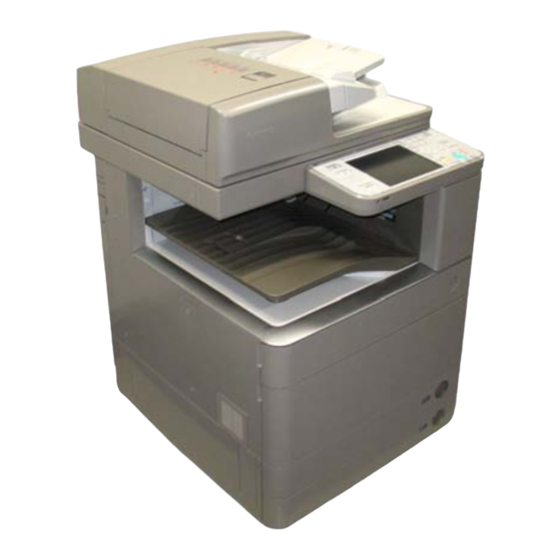
- Page 28 Product Overvew > Name of Parts > External View 1-12 Name of Parts External View F-1-6 DADF Front Cover Main Power Switch Front Upper Cover Stack Bypass Tray [10] Output Tray Paper Drawer4 [11] Control Panel Paper Drawer3 [12] Rear Cover Paper Drawer2 [13] Rear Rower Cover Paper Drawer1...
- Page 29 Product Overvew > Name of Parts > Cross Sectional View 1-13 Cross Sectional View [1] Reversal roller [16] Fixing separration guide [31] Cassette 2 feeding roller [2] 2-side delivery / delivery [17] Pressure roller [32] Cassette 2 separation unit roller [3] Secondary delivery roller [18] Film unit [33] Casset 2 pick-up roller [4] Second delivery entrance...
- Page 30 Product Overvew > Operation > Power Switch > How to turn ON / OFF the power and points to note 1-14 Operation ■ How to turn ON / OFF the power and points to note • While progress bar is kept displayed at power-on, HDD access is processing; thus, never Power Switch turn OFF the Main Power Switch.
- Page 31 Product Overvew > Operation > Description of Control Panel > Main Menu 1-15 Description of Control Panel ■ Main Menu iR ADVANCE C5051 / 5045 / 5035 / 5030 Series ■ Control Panel iR ADVANCE C5051 / 5045 / 5035 / 5030 Series Scan and Send Fax / I-Fax Inbox...
- Page 32 Product Overvew > Operation > Description of Control Panel > Difference of Settings / Registration menu 1-16 ■ Difference of main menu ■ Settings / Registration menu iR ADVANCE iR ADVANCE C5051 / 5045 / 5035 / 5030 Series iRC 3380 / 2880 Series C5151/5045/5035/5030 Series Copy Copy...
- Page 33 Product Overvew > Operation > Service Mode > Description display of service mode item 1-17 Service Mode ■ Description display of service mode item Enables to display the description of initial screen, large category, middle category and small It is possible to browse the usage method of service mode items in service mode. category.
- Page 34 Product Overvew > Operation > Service Mode > Enhancement of I/O information 1-18 ■ Enhancement of I/O information Device classification This mode is to check the signal input / output status of used electrical parts (sensor / motor / fan etc.). Searchability for target electrical parts has been improved in COPIER >...
- Page 35 Product Overvew > Operation > Service Mode > Screen display switch (level1 <-> level2) 1-19 ■ Subdivide COPIER > OPTION > BODY items Middle Middle category classification Details category name Feeding (pickup / delivery) FEED-SW Stack performance, motor speed fine-adjustment, COPIER DISPLAY COPIER...
- Page 36 Product Overvew > Operation > Service Mode > Screen display switch (level1 <-> level2) 1-20 Display Adjust Function Option Test Counter <VERSION > < 1/ 8 > < READY > <LEVEL 1 > DC-CON 43.44 R-CON 00.52 PANEL 4C.50 FEEDER 44.46 SORTER 54.53 42.4E DECK...
- Page 37 Technology ■ Basic■Configuration ■ ■ Controller■System■ ■ ■ Laser■Exposure■System ■ ■ Image■Formation■System ■ ■ Fixing■System ■ ■ Pickup■Feed■System ■ ■ MEAP ■ ■ Embedded■RDS ■ ■ Updater ■ Technology...
- Page 38 Technology■>■Basic■Configuration■>■Functional■Configuration■>■Basic■sequence■ Basic■Configuration ■ Basic■sequence■ ■ ● Sequence■at■Power-On ■ Functional■Configuration •■ Reader Main power switch ON The■machine■may■broadly■be■divided■into■the■following■functional■system■blocks;■document■ exposure■system■block,■controller■system■block,■laser■exposure■system■block,■image■ SREADY SSTBY Forwarding Forwarding formation■system■block,■fixing■system■block■and■pickup/feed■system■block. Reader Motor Shift shading Fixing shading Backwarding Backwarding White plate dust Scanning Lamp Document exposure system detection control Shading correction HP Sensor Exposure lamp...
- Page 39 Technology■>■Basic■Configuration■>■Functional■Configuration■>■Basic■sequence■ ● Print■sequence ■ Period■Definition Definition •■ Reader SREADY An■interval■in■which■the■shading■correction■is■executed■after■the■Start■ (Scanner■Ready) key■is■pressed. Start Key ON SSTBY An■interval■between■the■completion■of■the■shading■correction■and■ SSTBY SREADY SCRW SCFW SSTBY (Scanner■Standby) switching■the■Start■key■ON■/■turning■the■main■power■OFF. Forwarding Backwarding Backwarding Forwarding Forwarding Forwarding Reader Motor WMUP An■interval■in■which■the■drive■system■stops,■and■it■ends■when■the■ Backwarding Forwarding Backwarding Scanning Lamp (Warm-up) completion■requirements■of■the■fixing■assembly■startup■is■fulfilled.
- Page 40 Technology■>■Basic■Configuration■>■Functional■Configuration■>■Basic■sequence■ Period■Definition Definition SREADY An■interval■in■which■the■shading■correction■is■executed■after■the■Start■key■ (Scanner■Ready) is■pressed. SSTBY An■interval■between■the■completion■of■the■shading■correction■and■ (Scanner■Standby) switching■the■Start■key■ON■/■turning■the■main■power■OFF. PSTBY An■interval■in■which■the■copy■/■print■request■signal■can■be■accepted. (Print■Standby■State) PRINTR An■interval■between■the■reception■of■the■print■request■signal■and■the■state■ (Printer■Intial■Rotation) the■image■signal■is■sent. PRINT An■interval■in■which■all■■toner■is■transferred■on■the■paper,■and■the■paper■is■ delivered. LSTR An■interval■between■the■completion■of■the■paper■delivery■and■the■stop■of■ (Last■Rotation) all■drives. T-2-2 Technology■>■Basic■Configuration■>■Functional■Configuration■>■Basic■sequence■...
- Page 41 Technology■>■Controller■System■■>■Overview■>■Specifications■/■configuration Controller■System■ ■ Specifications■/■configuration ■ ● PCBs ■ Overview ■ Features ■ Using■a■new■controller■enables■high■speed■PDL■processing,■high■image■quality■and■high■ functionality. F-2-8 Parts■name Function,■specifications,■features Main■controller■ CPU:■1.2GHz,■Control■of■the■entire■system Main Controller PCB 1 Riser PCB Main Controller PCB 2 PCB■1 Various■controls■(memory,■control■panel,■electric■power,■voice),■I/Fs■(PCI,■USB■(host),■ F-2-6 Main■controller■PCB■1■controls■the■entire■system.■Main■controller■PCB■2■mainly■controls■ Flash■PCB Boot■program TPM■PCB To■generate■and■save■encryption■key image■processing. Available■only■when■TPM■settings■is■ON:■Management■Settings■>■Data■Management■ >■TPM■Settings■(default:■OFF) Main■controller■PCBs■1■and■2■are■connected■through■the■riser■PCB.
- Page 42 Technology■>■Controller■System■■>■Overview■>■Specifications■/■configuration ● Memory ■ Main■controller■PCB■2 Main■controller■PCB■1 J2032 BAT1 J2031 DDR2-SDRAM DDR2-SDRAM (M0) 512 MB + 512 MB 512 MB DDR2-SDRAM (M1) 1 GB BAT1 DDR2-SDRAM (P) F-2-9 512 MB Parts■name Function,■specifications,■features F-2-10 DDR2-SDRAM 2■slot■/■1GB■(standard) J2031:■512■MB Parts■name Function,■specifications,■features J2032:■512■MB■ DDR2-SDRAM■(M1) 1■GB■(standard)■/■clock■frequency:■200MHz Clock■frequency:■333■MHz Rasterizing,■rendering,■resolution■conversion,■coding■/■decoding Used■for■saving■image,■program■data...
- Page 43 Technology■>■Controller■System■■>■Overview■>■Specifications■/■configuration ● I/F,■connector ■ Main■controller■PCB■2 Main■controller■PCB■1 J1002 Bypass I/F Voice / open I/F J1010 J1003 Mini-USB Reader J1007 J3003 Image J1000 analysis I/F J1015 USB (D) Riser J1017 J1019 USB (H) Flash J1021 (1 line) Riser J1020 J1022 J1025 FAX-USB J1026 J1027 (2-4 line)
- Page 44 Technology■>■Controller■System■■>■Overview■>■Specifications■/■configuration ● Function■expansion■options ■ Main■controller■PCB■2 Main■controller■PCB1 Voice Operation/ Open I/F PCB Voice Guidance Expansion Bus Image analysis PCB Wireless LAN PCB IPSec PCB IPSec PCB ) n i Open I/F PCB Wireless LAN PCB Expansion Bus PCB F-2-13 Main controller PCB 2 Name Function,■specifications,■features F-2-14...
- Page 45 Technology■>■Controller■System■■>■Overview■>■Boot■sequence ■ HDD ■ ■ Boot■sequence ■ The■partitions■for■Advanced■Box■and■the■distribution■server■are■added. [ ]: program storage location User■Box■(same■as■the■existing■machine)■area■is■23GB■and■Advanced■Box■area■is■9GB. - Initialization process of hardware Advanced■Box■area■can■be■increased■by■installing■the■high-capacity■HDD■option. - Starting BIOS [Main controller PCB 1] - Starting IPL, OS FSTDEV Image data (User Box) [Flash PCB] TMP_GEN Universal data (temporary file) TMP_PSS For PDL spooling TMP_FAX...
- Page 46 Technology■>■Controller■System■■>■Overview■>■Shutdown■sequence 2-10 Related■Error■Codes■(major■error■codes): ■ Shutdown■sequence ■ Error■ Before■turning■OFF■the■main■power■switch,■it■is■necessary■to■perform■HDD■completion■ Error■description Code processing■(to■prevent■damage■on■the■HDD),■cooling■of■the■internal■printer■(to■prevent■fixed■ E602 Error■in■HDD toner■due■to■high■temperature)■and■exhaust■(to■prevent■smeared■image■due■to■chemical■ ■■■■ 0001 Failure■in■recognizing■HDD Boot■partition■(BOOTDEV)■is■not■found■at■startup. reaction■of■ozone■in■the■machine■and■photosensitive■drum).■This■sequential■processing■is■ 0002 There■is■no■system■software■for■the■main■CPU. called■“shutdown■sequence”■and■was■executed■on■the■legacy■models■manually■(by■holding■ 0006 There■is■no■system■software■for■the■sub■CPU. down■the■power■supply■switch■on■the■Control■Panel■for■a■specific■duration). E604 Failure■in■memory■(main■controller■PCB■1) ■■■■ 1024 Capacity■shortage■of■DDR2-SDRAM■(1GB■required) When■the■main■power■switch■is■turned■OFF■on■the■main■body,■Main■Controller■PCB■1■detects■ E613 Failure■in■memory■(main■controller■PCB■2) this■operation■and■then■the■shutdown■sequence■starts■/■executes■automatically. ■■■■ 1024 Capacity■shortage■of■DDR2-SDRAM■(M0,■M1)■(1GB■required) 1536 Capacity■shortage■of■DDR2-SDRAM■(M0,■M1)■(1.5GB■required) E748 Error■in■board■(Flash■PCB) In■addition,■hardware■shutdown■sequence■exists.■If■shutdown■sequence■is■not■executed■...
- Page 47 Technology■>■Controller■System■■>■Controls■>■Flow■of■Image■Data 2-11 Controls ● SEND ■ ■ Flow■of■Image■Data ■ Network ● Copy ■ Reader To DC Controller Image processing writing/reading Reader Resolution conversion, Image rotation, JPEG compression/extension Data conversion Tile raster conversion writing/reading JPEG encode Image data buffer (memory) Controller Image processing...
- Page 48 Technology■>■Controller■System■■>■Controls■>■Security■Features■(Encryption■Key,■Certificate,■Password■Protection) 2-12 ■ Security■Features■(Encryption■Key,■Certificate,■Password■ ■ ● Configuration■of■Security■Information ■ The■security■functionality■behaves■differently■depending■on■the■TPM■setting■on■the■UI. Protection) This■machine■provides■the■two■types■of■TPM■settings.■See■the■figure■below■for■the■security■ ● Overview ■ information■flow■in■each■setting. The■main■controller■PCB■1■of■the■host■machine■holds■a■new■PCB■named■“TPM■PCB”.■“TPM”■ stands■for■“Trusted■Platform■Module”,■which■collectively■refers■to■the■chip■set■for■generating■ - When the TPM setting is ON and■storing■encryption■keys■and■computing■public■key■encryption. TPM Key Main Controller PCB 1 TPM PCB (Temporarily stored in HDD) TPM PCB Public Key USB flash drive Backup Key for TPM failure...
- Page 49 Technology■>■Controller■System■■>■Controls■>■Security■Features■(Encryption■Key,■Certificate,■Password■Protection) 2-13 security■information■is■not■decodable■correctly■in■case■the■HDD■is■failed■or■formatted■because■ ● Preparation■before■Installing■TPM ■ the■public■key■information■stored■in■the■HDD■is■cleared.■If■this■occurs,■execute■“Initialize■All■ Before■installing■TPM,■ask■the■user■to■back■up■data. Data■/■Settings”■in■user■mode■to■set■the■TPM■setting■to■OFF.■This■will■maintain■the■password■ Follow■the■steps■below■to■back■up■data. information■in■the■SRAM■even■after■the■password■information■is■initialized. 1)■From■Remote■UI,■execute■Setting■/■Registration■>■Management■Setting■>■Data■ Management■>■Import■/■Export.■The■following■data■types■should■be■backed■up. - When the TPM setting is OFF: •■ Address■book■(see■*1) •■ Device■settings■(transfer■settings,■address■book,■frequently-used■Send■functions)■(see■*2) Backup Common •■ Setting■/■Registration •■ Printer■settings■can■be■exported Backup of •■ Favorites■stored■in■the■web■browser■(only■when■the■web■browser■is■enabled)■(see■*3) Common Key Password Password *1■Each■of■address■books■can■be■exported.■If■the■address■book■is■seen■as■a■part■of■device■ SRAM settings,■this■step■can■be■disregarded.
- Page 50 Technology■>■Controller■System■■>■Controls■>■Security■Features■(Encryption■Key,■Certificate,■Password■Protection) 2-14 ● Works■before■/■after■introduction ■ 1.■Enable■Functionality Execute■the■following■in■Setting■/■Registration■mode■(“TPM■setting”■is■OFF■by■default). MEMO:■Setup■of■“System■Management■PIN” 1.■Enable■the■feature It■is■recommended■for■users■(administrators)■to■set■the■system■management■PIN■ 2.■Backup■the■TPM■key before■installing■TPM.■The■TPM■key■is■backed■up■after■the■TPM■setting■is■set■to■“ON”.■ 3.■Restore■the■TPM■key However,■the■key■backup■is■permitted■only■once.■Unless■the■key■is■properly■backed■up,■ users■other■than■administrators■may■illegally■obtain■the■backup■file.■To■avoid■such■risks■ 4.■Disable■the■feature effectively,■the■system■management■PIN■should■be■set. The■works■above■are■basically■done■by■users. 1)Set■Management■Setting■>■Data■Management■>■TPM■Setting■to■“ON”. CAUTION: Setting■/■Registration When■the■TPM■setting■is■set■to■“ON”,■advice■users■on■the■following: Back■up■the■TPM■key■swiftly■after■the■setting■is■ON Keep■the■password■used■at■backup■securely Never■lose■the■USB■flash■drive■with■the■backup■TPM■key■file■saved The■TPM■key■should■be■restored■after■the■TPM■PCB■is■replaced■due■to■failures■or■the■ like. (TPM■key■restoration■is■enabled■only■at■TPM■PCB■replacement.) Unless■the■key■is■restored,■the■security■information■(passwords,■encryption■key,■and■ certificates)■cannot■be■used. When■the■key■restoration■is■failed■due■to■the■USB■flash■drive■lost■or■others,■“Initialize■All■ Data■/■Settings”■should■be■executed■to■reactivate■TPM■functionality.■The■security■may■ F-2-24 2)■Click■“Yes”,■and■restart■the■machine. be■undermined■if■the■old■Setting■/■Registration■data■are■maintained■as■it■is. F-2-25 This■setting■is■enabled■after■the■machine■is■restarted. 2-14 Technology■>■Controller■System■■>■Controls■>■Security■Features■(Encryption■Key,■Certificate,■Password■Protection)
- Page 51 Technology■>■Controller■System■■>■Controls■>■Security■Features■(Encryption■Key,■Certificate,■Password■Protection) 2-15 2.TPM■Key■Backup 3)■Click■[Password]■to■enter■the■password■(4-12■digits).■Then,■enter■the■password■for■ The■TPM■key■backup■file■can■be■stored■only■in■USB■flash■drive■(supported■file■system:■ confirmation. FAT32). Note■that■this■file■requires■the■memory■free■space■of■several■MBs. F-2-26 1)■Insert■the■USB■flash■drive■to■the■machine. The■USB■I/F■(host)■is■found■at■the■side■of■the■control■panel■as■well■as■the■main■ controller■PCB. CAUTION: Ensure■to■insert■only■one■USB■flash■drive. If■the■backup■job■is■started■with■2■or■more■USB■flash■drives■connected,■the■message■is■ shown■to■notify■that■the■backup■is■failed. F-2-28 MEMO: 4)■Click■[OK]■to■initiate■TPM■key■backup. The■USB■flash■drive■holds■the■TPM■key■backup■files■by■serial■number.■Thus,■backup■ files■for■multiple■machines■can■be■saved■in■a■USB■flash■drive. 2)Click■[Back■up■TPM■Key]■in■Management■Setting■>■Data■Management■>■TPM■Setting. F-2-27 F-2-29 5)■Click■[OK]■on■Backup■Completion■Screen■and■remove■the■USB■flash■drive. 2-15 Technology■>■Controller■System■■>■Controls■>■Security■Features■(Encryption■Key,■Certificate,■Password■Protection)
- Page 52 Technology■>■Controller■System■■>■Controls■>■Security■Features■(Encryption■Key,■Certificate,■Password■Protection) 2-16 3.■Restore■of■TPM■key CAUTION:■The■following■may■cause■failures■in■backup. Procedure■is■about■the■same■as■the■backup■work. If■any■of■the■following■is■detected,■the■backup■process■is■aborted■and■the■message■ Difference■between■restore■work■and■backup■work: and■the■cause■for■the■failure■are■shown■on■the■screen.■Take■an■appropriate■measure■to■ Rebooting■is■necessary■(turn■OFF■and■then■ON■the■main■power)■after■completion■of■restore■ recover■this. work. •■ The■USB■flash■drive■is■not■inserted■to■the■machine •■ 2■or■more■USB■flash■drives■are■inserted■to■the■machine 1)■Connect■the■USB■memory■that■saves■TPM■key. 2)■Select■the■following:■Management■setting■>■Data■management■>■TPM■setting;■and■ •■ The■USB■flash■drive■has■insufficient■free■memory■space click■[Restore■TPM■key]. •■ The■USB■flash■drive■is■write-protected •■ No■key■is■found CAUTION:■The■USB■flash■drive■should■be■securely■stored. Give■advice■users■on■the■following■points. •■ The■USB■flash■drive■should■be■securely■stored •■ Once■the■TPM■key■backup■file■is■saved■in■the■USB■flash■drive,■never■save■the■ backup■file■on■a■server■or■the■like■accessible■to■unanimous■users. F-2-30 MEMO:■Name■of■TPM■key■backup■file 3)■Enter■the■password■set■in■the■backup■process. The■serial■number■for■the■machine■is■automatically■assigned■as■the■backup■file■name. 4)■Click■[OK]■on■Start■Restoration■Screen.■The■restoration■process■is■started. 5)■Click■[OK]■on■Restoration■Completion■Screen.■Remove■the■USB■flash■drive■and■turn■ OFF/■ON■the■main■power■switch. 2-16 Technology■>■Controller■System■■>■Controls■>■Security■Features■(Encryption■Key,■Certificate,■Password■Protection)
- Page 53 Technology■>■Controller■System■■>■Controls■>■Security■Features■(Encryption■Key,■Certificate,■Password■Protection) 2-17 4.■Disable■the■feature CAUTION:■The■following■may■cause■failures■in■restoration. To■set■“OFF”■for■the■TPM■setting,■execute■[Initialize■All■Data■/■Settings]. If■any■of■the■following■is■detected,■the■restoration■process■is■aborted■and■the■message■ and■the■cause■for■the■failure■are■shown■on■the■screen.■Take■an■appropriate■measure■for■ recovery. •■ The■USB■flash■drive■is■not■inserted■to■the■machine •■ 2■or■more■USB■flash■drives■are■inserted■to■the■machine •■ The■USB■flash■drive■is■security-protected •■ No■TPM■key■is■saved■in■the■USB■flash■drive •■ The■TPM■key■saved■in■the■USB■flash■drive■is■not■for■the■machine •■ The■wrong■password■is■entered •■ After■the■TPM■key■was■backed■up,■[Initialize■All■Systems/■Settings]■was■executed •■ SRAM■(the■main■controller■PCB■1)■or■HDD■is■crashed F-2-31 CAUTION:■Points■to■note■when■disabling■functionality To■disable■the■use■of■TPM,■all■data■and■settings■should■be■initialized.■If■this■is■executed,■ user■information■saved■in■the■HDD/■SRAM■is■totally■cleared.■Ensure■to■back■up■the■data■ before■disabling■TPM■settings. List■of■data■to■be■cleared •■ Data■saved■in■BOX/■Advanced■Box •■ Data■saved■in■Inbox■(Fax■Box/■System■Box) •■ Destination■data■registered■in■Address■Book •■ Read■mode■registered■using■Send■function •■ Mode■memory■registered■using■Copy/■Box■function •■...
- Page 54 Technology■>■Controller■System■■>■Controls■>■Security■Features■(Encryption■Key,■Certificate,■Password■Protection) 2-18 Key■pair■and■server■certificate■registered■in■Management■Setting■(Setting/■Registration)■>■ ● Overview■of■Actions■taken■against■Troubles ■ [Device■Management]■>■[Certificate■Settings] Location■ TPM■Setting■=■ON TPM■Setting■=■OFF Relevant■Error■Code with■failure Steps■of■data■restoration■after■recovery TPM■PCB 1.■Check■the■TPM■PCB■connection N/A■(TPM■PCB■is■ Initially■E746-0031■is■ The■restoration■process■triggers■Setting/■Registration■>■Management■Setting■>■Data■ 2.■Replace■the■TPM■PCBs not■in■use■when■the■ shown■on■the■screen.■ 3.■Turn■OFF/■ON■the■power TPM■setting■is■set■to■ When■the■power■is■turned■ Management■>■Import/■Export■>■Import/■Export■Setting/■Registration■on■the■UI. 4.■See■the■section■of■“Restoring■TPM■ OFF.) OFF/ON■after■the■TPM■ The■data■listed■below■cannot■be■restored,■thus■should■be■set■again. Key”■to■restore■the■TPM■key. PCB■is■replaced,■E746- 5.■Turn■OFF/■ON■the■main■power■for■ 0032■is■shown■(only■when■ recovery the■TPM■setting■is■set■to■ Environment■Settings ON). •■ Paper■settings 1.Replace■the■HDDs. 1.■Replace■the■...
- Page 55 Technology■>■Controller■System■■>■Controls■>■Security■Features■(Encryption■Key,■Certificate,■Password■Protection) 2-19 ● Related■Error■Code ■ ● Security■Information■Storage■Location ■ Error■ Storage■ Backup■ Error■description,■Assumed■cause,■remedy Data■Type Function Name■of■Data Code Location Availability E746 Error■in■encryption Password/■ BOX■Password ■■■■ 0031 Error■in■hardware Password/■ Password■for■Fax■BOX Assumed■cause The■TPM■PCB■is■not■mounted;■the■TPM■PCB■for■the■other■machine■is■ mounted;■the■TPM■chip■is■crashed. Password/■ SEND Password■for■a■file■destination■of■Address■Book Remedy Mount■the■TPM■PCB■for■the■machine;■replace■with■the■new■TPM■PCB 0032 Error■occurred■but■the■system■is■recoverable Password/■ MEAP Authentication■information■registered■by■local■device■ Assumed■cause Keys■are■unmatched authentication■via■SSO-H Remedy...
- Page 56 Technology■>■Controller■System■■>■Controls■>■High■capacity■HDD■(Option) 2-20 ■ High■capacity■HDD■(Option) ■ Storage■ Backup■ Data■Type Function Name■of■Data Location Availability The■HDD■capacity■mounted■on■this■machine■is■80GB■as■standard.■Mounting■a■2.5■inch■/■ SRAM Password/■ Network Policy■common■key■for■IPSec 250GB■HDD-D1■(option)■makes■250GB■in■HDD■capacity.■High■capacity■is■required■in■the■case■ SRAM Password/■ Network User■name■and■password■for■PEAP/TTLS■ of■saving■large■amounts■of■data■with■“Advanced■Box.” authentication SRAM Password/■ Others Password■for■FAX■receipt Mounting■this■option■increases■capacity■for■Advanced■Box. 9GB:■in■the■case■of■80GB■HDD■capacity SRAM Password/■ Others Department■management■data■(including■System■ Manager■password) 114GB:■in■the■case■of■250GB■HDD■capacity SRAM Encryption■ Authentication■and■encryption■keys■for■SNMPv3 SRAM Password/■...
- Page 57 Technology■>■Controller■System■■>■Controls■>■HDD■mirroring■feature■(option) 2-21 ■ HDD■mirroring■feature■(option) ■ ● Works■before■using■this■functionality■(installation) ■ ● Overview ■ HDD1 is connected to Ch A on the Install the mirroring PCB and LED PCB mirroring PCB for HDD1 This■option■enables■HDD■data■mirroring■(RAID1). When■one■HDD■is■crashed,■the■other■HDD■backs■up■the■operation.■This■minimizes■the■ Slot.2 (HDD2) downtime■due■to■crash,■thus■enhancing■the■reliability■as■the■document■server. Slot.1 (HDD1) Mirroring■is■performed■in■the■following■2■ways■depending■on■HDD■capacities■(80GB■or■ CH B 250GB).
- Page 58 Technology■>■Controller■System■■>■Controls■>■HDD■mirroring■feature■(option) 2-22 ● List■of■operation■status■(LED) ■ MEMO: HDD■operation■statuses■are■indicated■with■4■LEDs■mounted■on■the■LED■PCB. •■ This■machine■can■be■used■even■during■“rebuild”■process■(operation■is■performed■with■ HDD1) The■green■LED■shows■that■the■operation■is■normally■in■progress,■while■the■red■LED■indicates■ •■ The■HDD■will■not■be■damaged■even■if■turning■OFF■the■power■during■“rebuild”■process.■ any■failures. “Rebuild”■is■resumed■once■the■power■is■turned■ON■the■next■time.■This■does■not■apply■in■ the■case■of■blackout■or■disconnecting■the■power■code■during■“rebuild”■process ● HDD■reading■/■writing■operation ■ Ch A Ch B At reading: At writing: (HDD2) (HDD1) Data is read by HDD1 (master HDD) The same data is written to each HDD at only the same timing Main controller PCB 2...
- Page 59 Technology■>■Controller■System■■>■Controls■>■HDD■mirroring■feature■(option) 2-23 ● Description■of■Modes ■ Mode■Flow■at■Start-up The■mirroring■system■of■this■machine■consists■of■4■modes. Turn ON Main Power Switch The■modes■in■parentheses■show■the■mirroring■system■statuses. The■status■flows■among■the■modes■below■during■operation. Flow to Mode at Previous Job Completion The■table■below■lists■descriptions■of■modes■and■operational■overview. Halt Mode Degrade Mode Rebuild Mode Mirror Mode Name■of■Mode Description Master■HDD■Status Backup■HDD■Status Mirror■Mode Both■HDDs■are■normally■ In■normal■operation In■normal■operation See Overview of Trouble Trouble Trouble Recovery...
- Page 60 Technology■>■Controller■System■■>■Controls■>■HDD■mirroring■feature■(option) 2-24 Mode■Flow■during■Operation ● Overview■of■Trouble■Recovery ■ When■any■trouble■occurs■in■the■mirroring■system,■take■the■action■for■recovery■appropriate■to■ each■mode. Mirror Mode The■HDD■in■trouble■can■be■located■by■the■red■LED■on■the■LED■PCB. In■case■the■master■HDD■cannot■be■located,■turn■OFF/■ON■the■power■to■check■whether■the■ Trouble green■LED■is■lit■on■the■LED■PCB. The■firstly■blinked■green■LED■(ChA■or■ChB)■in■a■high■speed■tells■the■Master■HDD,■which■is■ Either HDD In which HDD? accessed■firstly. The■green■LED■not■lit■on■a■channel■tells■the■location■of■Backup■HDD. Degrade Mode Both HDDs See Overview of Trouble Recovery HDD1■ HDD2■ Name■of■ (ChA) (ChB) Halt Mode Status Action■for■Recovery Master HDD Mode Red■...
- Page 61 Technology■>■Controller■System■■>■Controls■>■Removable■HDD■(option) 2-25 ● Points■to■Note■in■Servicing■concerning■Mirroring■Functionality ■ ■ Removable■HDD■(option) ■ 1.■The■modes■other■than■Mirror■Mode■indicate■troubles,■which■require■swift■recovery. This■option■enables■easier■HDD■mounting■(slot-out/■in)■at■power-OFF■(see■*1).■In■addition,■the■ The■power■can■be■turned■OFF■even■during■Rebuild■process.■However,■it■is■recommended■ HDD■slot■can■be■locked. not■to■turn■off■the■power■and■wait■until■the■mode■flows■to■Mirror■Mode.■In■addition,■HDD■ Potential■use■case:■To■enhance■information■securities■in■government■offices■or■enterprises removal■after■power-OFF■is■guaranteed■only■in■Mirror■Mode. •■ Remove■the■HDD■after■business■hours■to■store■in■a■safe■box. •■ Mount■the■HDD■before■business■hours.■Lock■the■slot■during■operation. 2.■The■mirroring■board■controls■Master■HDD■and■Backup■HDD.■This■control■is■performed■ based■on■the■HDD■serial■number■and■the■model■serial■number■instead■of■slot■locations. *1:■The■following■conditions■are■required■to■replace■HDDs■at■power-ON. If■HDDs■are■replaced■in■a■careless■manner■during■servicing■in■the■field,■the■Master■and■ •■ -■Removable■HDD■is■extended Backup■HDDs■may■be■switched. •■ -■Either■HDD■is■in■trouble Ex)■When■the■master■HDD■is■in■trouble,■the■mirroring■board■automatically■recognizes■ the■backup■HDD■as■the■master.■Thus,■the■master■and■backup■HDDs■are■switched■ even■without■changing■the■slot■locations. If■the■Master■HDD■cannot■be■located,■turn■OFF/■ON■the■power■to■check■on■which■channel■ the■green■LED■is■lit■on■the■LED■PCB. The■firstly-blinked■LED■(ChA■or■ChB)■shows■the■Master■HDD,■which■is■accessed■firstly■after■ power-on. 3.■For■users■who■intend■to■use■the■removable■and■mirroring■functionality■concurrently,■instruct■ them■not■to■change■the■removable■HDD■location■in■advance. Change■of■HDD■locations■after■power-OFF■is■allowed■as■specifications■only■in■Mirror■Mode. Otherwise,■HDD■removal■or■change■of■location■is■not■guaranteed. 4.■The■following■conditions■are■required■to■replace■HDDs■at■power-ON. •■...
- Page 62 Correct Correct HDD controller (Protection property) employs■an■unconventional■approach■to■achieve■HDD■encryption■and■mirroring■functionality■ It is not possible to decode. with■the■dedicated■chipset■on■a■board■(Canon■MFP■Security■Chip■Version■2.00).■Since■the■two■ Encryption functions■are■operated■in■a■HDD,■the■encryption■functionality■can■be■independently■enabled. Correct Controller Correct HDD encryption not authorized (Protection property) board ● Data■Encryption■Mechanism ■ It is not possible two-way authentication The■encryption■board■receives■signals■transmitted■from■the■controller■board,■and■encrypts■...
- Page 63 Technology■>■Controller■System■■>■Controls■>■HDD■Encryption/■Mirroring■Kit■(optional) 2-27 ● Actions■against■Troubles■–■Overview ■ <Points■to■Note■in■Initialization■using■USB> The■screen■below■is■shown■on■the■control■panel■when■E602-2000■occurred■and■the■machine■ Servicing User■data Recovery Action is■started■in■safe■mode■using■the■USB■flash■memory■with■system■data■stored. HDD■ cleared Replace■HDDs 1)■Format■the■HDD The■message■as■shown■in■the■figure■below■is■displayed. replacement 2)■Install■the■system■software Encryption■ cleared Install■HDD■encryption■ 1)■Replace■encryption■board Select■“0”■when■you■are■ready■to■initialize■the■encryption■board. board■ Kit■ 2)■Initialize■Encryption■Board■(see■*1) replacement 3)■Format■the■HDD 4)■Install■the■system Encryption board error occurred. Main■controller■ cleared Clear■the■key■for■HDD■ 1)■Initialize■the■encryption■board■(see■*1) Check connection 2■replacement■...
- Page 64 Technology■>■Controller■System■■>■Controls■>■HDD■Encryption/■Mirroring■Kit■(optional) 2-28 ● Relevant■Error■Codes ■ E610■and■detailed■codes E602■and■detailed■codes Detailed■ E■code Cause■(Detected■Error) Actions Code Detection■ E■code Description Cause Actions E610 Failure■in■the■HDD■encryption■key Timing 0001 Failure■in■the■HDD■encryption■key■ Ask■the■user■to■check■the■hardware■ E602 Authentication■Error Error■in■authentication■ Start-up Check■connections■between■ (Error■in■hardware■configuration).■No■ configuration. ■■-2000 between■the■host■ the■encryption■board■and■ encryption■board■is■installed. machine■and■the■ the■HDD■and■between■the■ 0002 Failure■in■the■HDD■encryption■key■ Ask■the■user■to■check■the■hardware■ encryption■board encryption■board■and■the■main■...
- Page 65 Technology■>■Controller■System■■>■Service■Operations■>■Points■to■note■at■servicing 2-29 Service■Operations ■ When■Replacing■Parts■ ■ Parts■name Remedy Reference Backup■of■the■set/registered■data■ HDD■format■ Downloading■system■software■ Restoring■the■backup■data■ Executing■“Auto■Adjust■Gradation■(Full■Adjust)” Main■Controller■PCB■1 Transferring■the■parts■from■old■PCB■to■new■PCB Main■Controller■PCB■2 Backup■of■the■set/registered■data■ Transferring■the■parts■from■old■PCB■to■new■PCB■ Restoring■the■backup■data TPM■PCB When■TPM■setting■is■“ON”:Restoring■the■TPM■key T-2-21 ■ Consumables ■ ■ Points■to■note■at■servicing ■ 2-29 Technology■>■Controller■System■■>■Service■Operations■>■Points■to■note■at■servicing...
- Page 66 Technology■>■Laser■Exposure■System■>■Overview■>■Overview 2-30 Laser■Exposure■System Laser Scanner Unit 1 Laser Scanner Unit 2 Overview Imaging Lens ■ Overview ■ Reflection Mirror To■realize■the■high-speed■printing,■this■machine■adopts■the■2■Laser■Scanner■Units■and■the■ Laser■Driver■of■each■color■executes■laser■scanning■with■4-beam. imageRUNNER■ADVANCE■C5051■/■C5045■employs■4■beam■and■C5035■/■5030■employs■2■ beam. Imaging Lens Skew Correction Motor C (M33) Skew Correction Motor Bk (M34) Reflection Mirror Scanner Laser Scanner Unit 2 Skew Correction Motor Y (M31) Mirror Imaging Lens...
- Page 67 Technology■>■Laser■Exposure■System■>■Overview■>■Specification 2-31 ■ Specification ■ Item Description Wavelength 775■to■800nm Laser■type Red■color■laser■(non-visible■light) Laser■output 10mW Number■of■laser■scanner■unit Number■of■laser■light imageRUNNER■ADVANCE■C5051■/■C5045:■4■beam■for■each■color imageRUNNER■ADVANCE■C5035■/■C5030:■2■beam■for■each■color Resolution 1200dpi Motor■type Brushless■motor Number■of■motor■rotation imageRUNNER■ADVANCE■C5051■/■C5045:■Approx.■29100rpm imageRUNNER■ADVANCE■C5035■/■C5030:■Approx.■37800rpm Number■of■scanner■mirror■facet 6■facet■(phi■40) Control■list Laser■ON■/■OFF■control Horizontal■scanning■synchronous■control Vertical■scanning■synchronous■control APC■control Laser■scanner■motor■control BD■correction■control Laser■shutter■control Image■tilt■correction■control T-2-22 2-31 Technology■>■Laser■Exposure■System■>■Overview■>■Specification...
- Page 68 Technology■>■Laser■Exposure■System■>■Various■Controls■>■Overview 2-32 Various■Controls DC Controller (UN1) Laser Driver PCB ■ Overview ■ Laser ON/OFF control Item Operation■description Laser Driver PCB Laser■ON■/■OFF■control Laser■light■is■turned■ON■/■OFF■according■to■the■combination■of■ laser■control■signal Horizontal scanning Scanner Motor Horizontal■scanning■ To■align■the■writing■start■position■in■horizontal■scanning■direction. synchronous control synchronous■control Vertical■scanning■synchronous■ To■align■the■writing■start■position■in■vertical■scanning■direction. control Vertical scanning APC■control To■make■the■laser■light■per■1■line■consistent■amount. synchronous control Laser■Scanner■Motor■Control To■rotate■the■scanner■mirror■by■the■specified■speed.
- Page 69 Technology■>■Laser■Exposure■System■>■Various■Controls■>■Horizontal■scanning■synchronous■control 2-33 ■ Laser■ON■/■OFF■control ■ ■ Horizontal■scanning■synchronous■control ■ ● Purpose ● Purpose ■ ■ Laser■light■is■turned■ON■/■OFF■according■to■the■combination■of■laser■control■signals. This■is■to■align■the■writing■start■position■in■horizontal■scanning■direction. ● Execution timing ■ ● Execution timing ■ After■the■power■ON Per■1■line ● Control detail ■ ● Execution time ■ DC■Controller■switches■the■4■modes■(forcible■OFF■mode,■APC■mode,■Print■mode■and■standby■ Approx.■7.5µs mode)■according■to■the■laser■control■signal. ● Control detail ■...
- Page 70 Technology■>■Laser■Exposure■System■>■Various■Controls■>■Vertical■Scanning■Synchronous■Control 2-34 ■ Vertical■Scanning■Synchronous■Control ■ Laser Scanner Unit 1 Y Laser ● Purpose Y Laser Driver ■ VDO_Y BD_YM This■is■to■align■the■writing■start■position■in■vertical■scanning■direction. BD Sensor (Y, M) ● Execution timing ■ VDO_M M Laser M Laser Driver Per■printing ● Execution time ■ Main Controller Controller (UN1) Laser Scanner Unit 2 500ms...
- Page 71 Technology■>■Laser■Exposure■System■>■Various■Controls■>■APC■(Auto■Power■Control)■control 2-35 ■ APC■(Auto■Power■Control)■control ■ Print instruction ● Purpose ■ Reference signal This■is■to■make■the■laser■light■for■1■line■consistent■amount. Video request signal ● Execution timing ■ (PVREQ) Per■each■line■(before■image■writing) About15ms Video signal (VDO) ● Execution time ■ Approx.■2■µs About15ms F-2-53 ● Control details ■ 1)■DC■Controller■outputs■the■laser■control■signal■to■the■Laser■Driver■IC■on■the■Laser■Driver■ PCB. 2)■APC■mode■is■specified■to■the■Laser■Driver■IC■and■it■forcibly■emits■the■laser■diode■of■each■ color.■At■the■same■time,■each■laser■driver■IC■monitors■the■laser■diode■(LD)■on■the■photo■...
- Page 72 Technology■>■Laser■Exposure■System■>■Various■Controls■>■Laser■scanner■motor■control 2-36 ■ Laser■scanner■motor■control ■ Laser Scanner Unit 1 ● Purpose ■ Y Laser Y laser control signal This■is■to■rotate■the■scanner■mirror■by■the■specified■speed. Y Laser Driver ● Execution timing ■ At■power-ON,■per■printing M Laser ● Execution time ■ M laser control signal M Laser Driver Approx.■3s■(at■power-ON),■approx.■1s■(at■printing) ●...
- Page 73 Technology■>■Laser■Exposure■System■>■Various■Controls■>■Laser■scanner■motor■control 2-37 Laser Scanner Unit 1 Related■error■code ACC1 E100-0100:■BD■error■(laser■scanner■unit■1)■ Scanner Motor (Y, M) When■the■Laser■Scanner■Unit■1■(YM■laser)■is■started■or■print■operation■is■processing,■if■the■BD■ DEC1 signal■cannot■be■detected■after■the■specified■time. E100-0300:■BD■error■(laser■scanner■unit■2) When■the■Laser■Scanner■Unit■2■(CBk■laser)■is■started■or■print■operation■is■processing,■if■the■BD■ signal■cannot■be■detected■after■the■specified■time. E100-B000:■BD■error■(laser■scanner■unit■1/2) When■the■Laser■Scanner■Unit■1/2■is■started■or■print■operation■is■processing,■if■the■BD■cycle■ BD_YM cannot■be■detected■after■the■specified■time. BD Sensor (Y, M) Y Laser Driver M Laser Driver E102-0100:■EEPROM■error■(laser■scanner■unit■1) Reading■error■of■EEPROM■on■Laser■Driver■(Y)■occurs. DC Controller (UN1) E102-0300:■EEPROM■error■(laser■scanner■unit■2) Laser Scanner Unit 2 Reading■error■of■EEPROM■on■Laser■Driver■(C)■occurs.
- Page 74 Technology■>■Laser■Exposure■System■>■Various■Controls■>■BD■correction■control 2-38 ■ BD■correction■control ■ START ● Purpose ■ This■is■to■correct■the■displacement■of■writing■start■position■of■each■color■laser■due■to■the■angle■ Scanner motor control finish variation■of■scanner■mirror■facet. (Constant-speed rotation detection) ● Execution timing ■ At■power-ON,■per■printing BD interval measurement Constant interval Constant interval Narrow interval Constant interval ● Execution time ■ Within■approx.■0.5s■or■less Writing start correction value calculation ●...
- Page 75 Technology■>■Laser■Exposure■System■>■Various■Controls■>■Laser■shutter■control 2-39 ■ Laser■shutter■control ■ Bk Laser Shutter Color Laser Shutter ● Purpose ■ Bk Shutter Lever This■is■to■prevent■the■residue■toner■from■sticking■to■the■dust-prevention■glass.■Or■to■prevent■ the■laser■light■from■emitting■to■the■machine■inside■when■the■front■cover■/■right■cover■is■opened. Color Shutter Lever ● Execution timing ■ After■power-ON Bk Shutter Cam ● Execution time ■ Drive Shaft Approx.■3s■(at■power-ON),■approx.■1s■(when■scanner■motor■is■started■or■cover■is■opened) Laser Shutter Motor (M28) Color Shutter Cam ●...
- Page 76 Technology■>■Laser■Exposure■System■>■Various■Controls■>■Image■tilt■correction■control 2-40 ■ Image■tilt■correction■control ■ Laser shutter position Relation of shutter lever and cam Sensor lever position For Bk For color For Bk For color ● Purpose ■ This■is■to■prevent■the■gap■of■laser■emission. (PS29) Close Close ● Execution timing ■ Shutter Sensor Lever Lever At■power-ON,■per■total■360■sheets■printing Shutter Cam ●...
- Page 77 Technology■>■Laser■Exposure■System■>■Various■Controls■>■Image■tilt■correction■control 2-41 Photosensitive Drum Imaging Lens Skew Correction Motor Position relation of imaging lens and arm Skew Correction Motor Imaging Lens Imaging Lens Before correction Imaging Lens Photosensitive Drum Skew Correction Motor Position relation of imaging lens and arm Imaging Lens After correction Arm Cam F-2-59...
- Page 78 Technology■>■Laser■Exposure■System■>■Service■Works■>■Points■to■note■at■servicing 2-42 Service■Works ■ Periodically■replaced■parts ■ There■is■no■periodically■replaced■part. ■ Consumables ■ Parts■Name Parts■Number Estimated■Life Dust-blocking■Glass■cleaning■pad FL2-9476 150k T-2-25 ■ Periodical■service■list ■ Parts■name:■Dust-blocking■Glass Expected■life:■per■50K■sheet Operation:■Clean■it■with■the■Dust-blocking■Glass■Cleaning■tool■stored■in■the■machine. Dust-blocking glass cleaning tool F-2-61 ■ Operation■at■parts■replacement ■ N■/■A ■ Points■to■note■at■servicing ■ N■/■A 2-42 Technology■>■Laser■Exposure■System■>■Service■Works■>■Points■to■note■at■servicing...
- Page 79 Technology■>■Image■Formation■System■>■Overview■>■Specifications 2-43 Image■Formation■System ■ Specifications ■ Item Function/Method Photosensitive■ Material Overview Drum O/D■of■drum 30mm Cleaning Cleaning■blade ■ Overview ■ Process■speed imageRUNNER■ADVANCE■C5051=246mm/s,■ imageRUNNER■ADVANCE■C5045=215mm/s,■ Image■formation■system■of■this■machine■uses■the■magnetic■2-component■jumping■developing■ imageRUNNER■ADVANCE■C5035/5030=160mm/s method■for■developing■and■the■intermediate■transfer■method■for■transfer■to■create■toner■ Drum■heater Mounted■with■Bk■drum■as■a■standard. image. Assigned■as■an■option■for■color■drums. Developing■ Developing■cylinder 1pc■(single■developing) To■increase■life■of■the■image■formation■unit,■this■machine■uses■the■primary■transfer■ assembly Developing■method Dry,■2-component■jumping disengagement■method■as■a■new■technology. Toner Non-magnetic■negative■toner Following■shows■major■improved■points■compared■to■the■previous■iRC3880/2880■series. Toner■level■detection Not■available O/D■of■cylinder...
- Page 80 Technology■>■Image■Formation■System■>■Overview■>■Print■process 2-44 ■ Parts■configuration ■ ■ Print■process ■ ● Major■Parts ■ Delivery Fixing block Toner container 8. Fixing ITB cleaning block Transfer block Transfer 9. ITB cleaning assembly 7. Separation 6. Secondary transfer Toner supply 5. Primary transfer 5. Primary transfer 5.
- Page 81 Technology■>■Image■Formation■System■>■Overview■>■Print■process 2-45 ● Bias■Types ■ There■are■the■following■8■types■biases■used■on■this■machine. Bias■value Bias■name Bias■type Application■destination (Reference■value) Primary■charging■bias■(DC) Approx.■–600V Primary■Charging■Roller Primary■charging■bias■(AC) Approx.■1.5kVpp Flying■toner■blocking■bias■(DC) Approx.■-1.3kV Toner■Blocking■Terminal■Plate Developing■bias■(DC) Approx.■-400V Developing■Cylinder Developing■bias■(AC) Approx.■1.6kVpp Primary■transfer■bias Approx.■1.5kV Primary■Transfer■Roller Secondary■transfer■bias Approx.■3kV Secondary■Transfer■Outer■Roller Secondary■transfer■cleaning■bias Approx.■-1.0kV T-2-28 Aforementioned■biases■are■created■by■3■HVT■and■are■supplied■to■the■loads■used■in■the■ printing■process. Developing Developing Developing Developing subhigh subhigh subhigh subhigh...
- Page 82 Technology■>■Image■Formation■System■>■Controls■>■Pre-exposure 2-46 Controls ■ Pre-exposure ■ ● Pre-exposure■control ■ ■ Overview ■ Removing■residual■potential■on■the■photosensitive■drum■before■executing■the■primary■ Pre-exposure Image■stabilization■control charging■prevents■drum■ghost■during■continuous■print. ■■■■■■ Pre-exposure■control ■■■■■■ Drum■film■thickness■detection According■to■the■command■from■the■DC■controller■PCB,■the■pre-exposure■unit■exposes■(emits)■ D-max■control Primary■charging D-half■control LED■when■the■photosensitive■drum■is■rotated. ■■■■■■ Primary■charging■bias■control ARCDAT■control Emitting■LED■light■through■the■light■guide■removes■residual■potential■on■the■photosensitive■ Discharge■current■control PASCAL■control drum. Primary■charging■cleaning■control Color■displacement■correction■control To■make■up■for■the■lack■of■LED’s■light■intensity,■two■(2)■pre-exposure■LEDs■are■used■in■total:■ ATVC■control Developing/drum one■at■the■front■of■the■main■unit,■and■the■other■at■the■rear■of■the■main■unit. ■■■■■■ Developing■bias■control Toner■supply ACR■(Auto■Carrier■Refresh)■control ■■■■■■...
- Page 83 Technology■>■Image■Formation■System■>■Controls■>■Primary■charging 2-47 ■ Primary■charging ■ ● Primary■charging■bias■control ■ To■charge■the■surface■of■photosensitive■drum■to■be■uniform■negatively-charged■potential ● Overview ■ The■primary■charging■bias■(AC+DC■negative),■generated■by■HVT1/2■PCB,■is■applied■to■the■ This■machine■uses■the■roller■charging■method■for■primary■transfer. primary■charging■roller. To■prevent■image■fault■(white■spot/missing■image)■caused■by■residual■toner,■the■cleaning■ DC controller(UN1) brush■roller■is■added■to■clean■the■primary■charging■roller. Drum Photosensitive cleaner drum HVT1 /2(UN16/17) AC + DC negative Photosensitive drum Cleaning brush Primary charging roller roller F-2-67 Primary charging roller Cleaning brush roller F-2-68 ●...
- Page 84 Technology■>■Image■Formation■System■>■Controls■>■Primary■charging 2-48 Execution■time ● Primary■charging■cleaning■control ■ Within■1■second This■machine■may■not■be■able■to■collect■residual■toner■on■the■drum■because■this■machine■ uses■fine-grain■toner,■which■possibly■results■in■image■fault■(white■spot/missing■image)■due■to■ Operation■of■the■main■unit residual■toner■attached■on■the■primary■charging■roller. 1)■Current■monitoring■value■of■the■primary■charging■AC■bias■is■detected To■prevent■this■symptom,■the■cleaning■brush■roller■is■added■to■forcibly■remove■residual■toner■ 2)■Optimal■primary■charging■current■value■is■determined■according■to■the■result■of■the■ attached■on■the■primary■charging■roller. environment■sensor■(UN22)■and■the■current■monitoring■value The■drive■of■the■brush■roller■is■engaged■with■the■primary■charging■roller. 3)■The■primary■charging■AC■bias■is■determined■to■apply■to■the■primary■charging■roller Photosensitive Drum drum cleaner Primary charging AC HVT1 Current monitoring signal (UN16) Primary charging AC DC controller (UN1) HVT2 (UN17) Primary charging roller Current monitoring signal F-2-69 Related■error■codes:...
- Page 85 Technology■>■Image■Formation■System■>■Controls■>■Developing/drum 2-49 ■ Developing/drum ■ ● Developing■bias■control ■ To■create■toner■image■on■the■photosensitive■drum■after■the■toner■has■been■attached■on■the■ ● Developing■overview ■ photosensitive■drum Toner-blocking Control■description Developing electrode plate cylinder The■developing■bias■(AC,■DC■negative)■generated■by■HVT1/2■(UN16/17)■is■applied■to■the■ developing■cylinder •■ Developing■DC■bias:■bias■for■generating■potential■difference■from■the■photosensitive■drum■ Bias■value■is■determined■based■on■detection■result■of■the■drum■film■thickness Toner feeding screw B •■ Developing■AC■bias:■bias■for■improving■image■quality DC controller(UN1) HVT1/2(UN16/17) Developing motor M5 M8 AC+DC Developing cylinder ATR sensor (TS5 TS8) Toner feeding screw A...
- Page 86 Technology■>■Image■Formation■System■>■Controls■>■Developing/drum 2-50 ● ACR■(Auto■Carrier■Refresh)■control ■ ● Toner-blocking■bias■control ■ This■machine■introduced■a■method■to■supply■developer■(toner■+■carrier)■to■improve■life■(longer■ This■control■prevents■scattering■of■toner■on■the■developing■cylinder■due■to■deterioration■of■the■ life)■of■the■developing■assembly.■ developing■assembly. This■is■a■control■to■supply■developer■to■the■developing■assembly■and■also■discharge■ Developing■AC■bias■which■has■been■generated■by■HVT1■(UN16)■is■generated■to■be■negative■ developer■to■keep■optimal■developer■amount■in■the■developing■assembly. DC■bias■on■the■developing■sub■high■voltage■PCB■(UN43■to■46). This■control■prevents■deterioration■of■carrier,■which■had■been■occurred■due■to■reuse■of■ The■generated■bias■is■applied■to■the■toner-blocking■electrode■plate.■This■improves■retention■ developer■in■the■developing■assembly. strength■of■toner■on■the■developing■cylinder. The■Toner■Feed■Screw■A■&■B■drive■when■the■Developing■Motor■(M5■to■8)■drives■so■that■the■ DC controller(UN1) developer■will■be■exhausted.■The■developer■is■supplied■at■the■right■time■based■on■the■ATR■ control■result. HVT1/2 (UN16/17) Toner feeding screw A Return screw Flow of toner Toner discharge outlet Developing sub high voltage PCB Y/M/C/Bk (UN43 46) Toner-blocking electrode plate Developing...
- Page 87 Technology■>■Image■Formation■System■>■Controls■>■Developing/drum 2-51 ● Drum■overview ■ ● Drive■configuration ■ Pre-exposure LED light guide Drum motor Photosensitive drum M1 M4 Drum rotation sensor1 Drum rotation sensor2 (UN31 / 33 / 35 / 37) Pre-exposure LED (UN32 / 34 / 36 / 38) light guide Photosensitive drum Waste toner screw...
- Page 88 Technology■>■Image■Formation■System■>■Controls■>■Developing/drum 2-52 ● Detection■of■drum■(presence) ■ ● Old/new■detection■of■drum■unit ■ To■detect■if■the■drum■unit■is■installed■or■not To■detect■whether■the■drum■unit■is■new■or■old Execution■timing Detection■timing 1)■When■the■power■is■turned■ON 1)■When■the■power■is■turned■ON 2)■At■recovery■from■sleep■mode 2)■At■recovery■from■sleep■mode Detection■description Detection■description To■be■determined■by■current■monitoring■value■of■the■primary■charging■AC■bias To■check■state■of■the■fuse■that■is■attached■to■each■drum■unit In■case■that■current■monitor■value■is■less■than■the■specified■value■(1mA):■no■Drum■Unit There■is■a■fuse:■new■drum In■case■that■current■monitor■value■is■the■specified■value■(1mA)■or■more:■Drum■Unit■present Fuse■is■blown:■used■drum Execution■timing Operation■of■the■main■unit Within■1■second 1)■The■main■unit■checks■presence■of■the■fuse■attached■to■each■drum■(the■fuse■detection■signal■ is■monitored) Operation■of■the■main■unit 2)■If■there■is■a■fuse,■the■main■unit■clears■the■drum■film■thickness■detection■data■of■the■ Operation■of■the■main■unit■is■stopped■while■“No■drum■unit”■is■shown■on■the■control■panel. applicable■drum■unit,■which■is■kept■in■SRAM■(IC2). 3)■The■main■unit■cuts■the■fuse■(to■make■the■fuse■cut■signal■“H”) Primary charging AC Drum unit HVT1 Current monitoring signal (UN16) DC controller...
- Page 89 Technology■>■Image■Formation■System■>■Controls■>■Developing/drum 2-53 ● Drum■life■detection ■ MEMO: To■detect■life■of■the■Photosensitive■Drum. Fuse■cut■operation■is■executed■when■the■power■is■turned■ON■after■a■new■Drum■Unit■is■ installed. The■life■data■is■stored■in■the■SRAM■(IC2)■of■the■DC■Controller. Thus,■if■replacing■a■Drum■Unit■to■another■one■(new■one)■to■identify■a■cause■of■failure■at■ The■drum■life■value■can■be■checked■from■the■service■mode. a■field,■fuse■is■blown■and■the■drum■thickness■data■is■cleared. As■a■result,■even■though■the■original■Drum■Unit■is■installed■to■the■host■machine■again,■ the■host■machine■identifies■it■as■like-new■one■and■correct■print■image■may■not■be■output. Data■storage■ Target■drum Detection■items Reference■service■mode Unit With■consideration■to■above■matter,■do■not■use■a■new■Drum■Unit■when■identifying■a■ location cause■of■failure. Color■drum Primary■Charging■AC■Bias■ SRAM■(IC2)■ Display■of■the■drum■life■ %■(In■ (YMC) Monitor■value■(For■details,■ of■the■DC■ counter■value increments■ refer■to■"Drum■film■thickness■ Controller (COPIER■>■COUNTER■>■ of■approx.■ detection".) LF■>■Y-DRM-LF,■M-DRM- Related■service■mode LF,■C-DRM-LF) COPIER■>■FUNCTION■>■INSTALL■>■AINR-OFF■(fuse■cut■extend■on■new■drum■unit) Bk■drum...
- Page 90 Technology■>■Image■Formation■System■>■Controls■>■Developing/drum 2-54 ● Drum■heater■control ■ CAUTION:■The■drum■life■counter■value■of■color■drums■is■specified■according■to■the■ The■drum■heater■is■attached■below■the■photosensitive■drum■to■keep■stabilized■charging■and■ Drum■Film■thickness.■The■Drum■Film■thickness■is■calculated■from■the■monitor■value■of■ exposure■according■to■the■environmental■change■in■the■machine.■ the■primary■charging■DC■current. This■heater■works■only■when■the■main■power■switch■is■turned■OFF■while■the■environment■ When■the■current■value■detected■at■the■first■Drum■Film■thickness■detection■after■ switch■is■turned■ON. replacement■of■the■drum■varies■at■a■relatively■high■level,■the■drum■life■counter■value■in■ service■mode■is■displayed■"0%"■for■a■while■(approx.■20k■images)■in■some■cases.■The■ accuracy■becomes■increasingly■higher■as■the■drum■approaches■its■end■of■life. Photosensitive drum The■drum■life■detection■based■on■the■drum■film■is■a■detection■method■adopted■for■the■ first■time■in■this■machine,■and■realizes■drum■life■detection■more■accurate■than■that■of■ existing■models. 100% Drum heater Ideal drum life shif Drum life F-2-80 Image of actual drum life shift When the current is high at initialization (Image) F-2-79...
- Page 91 Technology■>■Image■Formation■System■>■Controls■>■Transfer/separation 2-55 ● Drum■rotation■speed■control ■ ■ Transfer/separation ■ This■control■is■performed■to■keep■a■uniform■drum■rotation■speed■in■order■to■increase■accuracy■ ● Overview ■ of■the■image■position■(color■displacement). Post-secondary transfer Drive roller static eliminator Execution■timing (steering roller) ITB scraper 1)■The■drum■rotates,■driven■by■the■drum■motors■(M1■to■M4).■ ITB Cleaning blade 2)■There■is■an■encoder■on■the■drum■shaft,■of■which■rotation■is■monitored■by■the■two■sensors■(Y:■ UN31/32,■M:■UN33/34,■C:■UN35/36,■Bk:■UN37/38,).■ Waste toner 3)■This■sensor■counts■the■drum■count■based■on■a■pulse,■and■feeds■back■the■drum■rotation■ feeding screw speed■to■the■drum■DC■controller■to■perform■speed■control. Primary transfer auxiliary roller Secondary transfer Primary transfer Primary transfer...
- Page 92 Technology■>■Image■Formation■System■>■Controls■>■Transfer/separation 2-56 ● Drive■configuration ■ ● Primary■transfer■disengagement■control ■ The■primary■transfer■roller■for■color■is■engaged■or■disengaged■to■keep■longer■life■of■the■image■ ITB motor formation■parts■(photosensitive■drum,■ITB) ITB displacement control motor ITB steering position sensor(PS24) Execution■timing ITB displacement sensor 1 to 4 (PS25 •■ Roller■to■be■engaged:■when■making■color■prints■(If■2■and■more■sheets■of■Bk■continues■ Primary transfer Drive roller detachment sensor 2(PS23) within■a■job■at■Color■+■Bk■mix■printing,■disengage■the■Primary■Transfer■Roller■when■printing■ (steering roller) Idol roller ITB scraper Primary transfer...
- Page 93 Technology■>■Image■Formation■System■>■Controls■>■Transfer/separation 2-57 ● Primary■transfer■bias■control ■ This■control■transfers■toner■on■the■photosensitive■drum■to■the■ITB. The■primary■transfer■bias■(DC),■which■has■been■generated■by■HVT2■(UN17),■is■applied■to■the■ primary■transfer■roller. Primary transfer Bias■value■is■determined■by■the■measurement■value■of■environment■sensor■1■(UN22) auxiliary roller DC controller(UN1) Support arm Drive shaft HVT2 (UN17) Sensor flag Primary transfer roller(M) Primary transfer Primary transfer disengagement roller(Y) motor(M15) Primary transfer detachment sensor 1(PS22) Primary transfer Support arm detachment sensor 2(PS23)
- Page 94 Technology■>■Image■Formation■System■>■Controls■>■Transfer/separation 2-58 ● Secondary■transfer■bias■control ■ ● ITB■displacement■correction■control ■ This■control■transfers■toner■on■the■ITB■to■the■paper. This■control■prevents■damage■on■the■ITB■due■to■displacement■of■the■ITB. The■secondary■transfer■bias■(DC),■which■has■been■generated■by■HVY3■(UN18),■is■applied■to■ the■secondary■transfer■outer■roller. Execution■timing Bias■value■is■determined■by■the■measurement■value■of■environment■sensor■2■(UN50)■and■the■ When■the■ITB■is■rotated paper■type. Control■description DC controller(UN1) 1)■The■ITB■displacement■sensors■(PS25■to■28)■detect■displacement■of■the■ITB. 2)■Drive■of■the■ITB■displacement■control■motor■(M14)■rotates■the■cam. HVT3 (UN18) The■cam■position■is■detected■by■the■steering■position■sensor■(PS24). 3)■Rotation■of■the■cam■moves■the■drive■shaft■up/down■to■tilt■the■steering■roller. Drive roller (steering roller) 4)■Tilt■of■the■steering■roller■generates■tension■difference■of■the■ITB■to■move■the■ITB■to■the■front■ or■rear. 5)■Repeating■steps■1)■through■4)■corrects■displacement■of■the■ITB. ITB steering position sensor(PS24) Drive shaft ITB displacement control motor(M14) Secondary transfer outer roller ITB displacement...
- Page 95 Technology■>■Image■Formation■System■>■Controls■>■Transfer/separation 2-59 ● ITB■cleaning■control ■ Related■Error■Codes To■remove■residual■toner■on■the■ITB E075-0002:■failure■in■ITB■steering■position■sensor E075-0003:■failure■in■ITB■displacement■control■(full■displacement■to■the■rear) Control■description E075-0004:■failure■in■ITB■displacement■sensor 1)■The■ITB■cleaning■blade■scrapes■toner■on■the■ITB. E075-0005:■Error/failure■in■searching■ITB■steering■HP 2)■Scraped■toner■is■fed■to■the■waste■toner■case■by■the■waste■toner■feeding■screw. E075-0103:■failure■in■ITB■displacement■control■(full■displacement■to■the■front) ITB motor MEMO: Following■table■shows■detection■result■of■the■ITB■displacement■sensor■and■operation■of■ the■main■unit. State■of■ITB■displacement■sensor Edge■state■of■ITB■belt Operation■of■main■unit PS25 PS26 PS27 PS28 Full■displacement■to■the■rear■ Error■code■(E075-0003)■stops■ (approx.■5.8mm■or■more) the■main■unit. Waste toner Displacement■to■the■rear■ Steering■roller■(rear)■is■moved■ feeding screw (approx.■4.0mm■to■5.7mm) down. Displacement■to■the■rear■ ITB cleaning blade Drive roller (approx.■2.1mm■to■3.9mm)
- Page 96 Technology■>■Image■Formation■System■>■Controls■>■Transfer/separation 2-60 ● Secondary■transfer■outer■roller■cleaning■control ■ ● Separation ■ To■prevent■soil■on■the■back■of■the■sheet■caused■by■soil■on■the■secondary■transfer■outer■roller Paper■is■separated■from■the■ITB■due■to■paper’s■elastic■force.■ In■the■case■of■thin■paper■which■has■low■elastic■force,■the■static■eliminator■reduces■potential■on■ Execution■timing the■back■surface■of■paper.■This■reduces■electrostatic■adsorption■of■paper■so■that■thin■paper■is■ 1)■At■warm-up■rotation■(fixing■temperature■is■less■than■50■deg■C,■jam■recovery) separated■from■the■ITB■more■easily. 2)■At■the■post-rotation Post-secondary transfer 3)■After■executing■image■stabilization■control■(creating■patch■image■on■the■ITB) static eliminator Secondary transfer inner roller Control■description The■secondary■transfer■bias■(see■Note■1),■which■has■been■generated■by■HVT3■(UN18),■is■ applied■to■the■secondary■transfer■outer■roller. Residual■toner■on■the■secondary■transfer■outer■roller■is■attached■to■the■ITB,■and■then■collected■ by■the■ITB■cleaning■unit. Secondary transfer Caution: outer roller Both■positive■bias■and■negative■bias■are■applied: Because■of■polarized-charged■(positive■and■negative)■residual■toner,■both■types■of■ residual■toner■need■to■be■removed. F-2-90 Therefore,■positively-charged■bias■is■applied■on■the■1st■cycle■of■ITB■while■negatively- MEMO: charged■bias■is■applied■on■the■2nd■cycle■of■ITB.
- Page 97 Technology■>■Image■Formation■System■>■Controls■>■Image■stabilization■control 2-61 ■ Drum■cleaning ■ ■ Image■stabilization■control ■ ● Overview ■ ● Overview ■ To■clean■residual■toner■on■the■photosensitive■drum To■prevent■image■fault■due■to■environmental■change■or■deterioration■of■photosensitive■drum■ Residual■toner■on■the■drum■is■scraped■by■the■drum■cleaning■blade. to■make■stable■print■image Then,■rotation■of■the■waste■toner■screw■feeds■the■residual■toner■to■the■waste■toner■case. DC controller(UN1) Main controller 2 ATVC control Photosensitive drum ATR control PASCAL control Toner Toner Toner Toner Patch sensor D-half control (Front/Center/Rear) (UN47 / UN48 / UN49) Color displacement...
- Page 98 Technology■>■Image■Formation■System■>■Controls■>■Image■stabilization■control 2-62 Control■types Execution■ Execution■condition Required■time■(sec) timing At■power■ON At■normal■condition Model■A:■approx■20.9■Model■B:■approx■29.5 ○ ○ ○ ○ ○ ○ ○ ○ H/H■environment Model■A:■approx■46.0■Model■B:■approx■68.1 ○ ○ ○ ○ ○ ○ ○ ○ ○ ○ At■recovery■ Sleep■is■less■than■8■hours Model■A:■approx■12.1■Model■B:■approx■17.6 ○ ○ ○ ○ from■sleep Sleep■is■8■hours■or■more Model■A:■approx■20.9■Model■B:■approx■29.5 ○...
- Page 99 Technology■>■Image■Formation■System■>■Controls■>■Image■stabilization■control 2-63 ● Drum■film■thickness■detection ■ ● D-max■control ■ To■detect■use■condition■of■the■photosensitive■drum This■control■determines■optimal■developing■DC■bias,■primary■charging■DC■bias,■laser■power■ output. Execution■timing 1)■When■the■power■is■turned■ON. Execution■timing 2)■Every■time■making■print 1)■When■replacing■a■drum■unit■or■developing■assembly. 2)■At■every■post-rotation■after■the■total■reaches■1000■prints. Control■description 3)■Power■ON■(High■temperature■and■humidity)and■corrects■the■each■color■developing■DC■ 1)■The■drum■count■value■is■calculated■by■the■monitor■signal■of■the■primary■charging■AC■bias. bias,■primary■charging■DC■bias,■laser■power■output■to■realize■the■target■density. 2)■The■count■value■calculated■in■step■1)■above■is■added■to■the■drum■count■value■that■has■been■ kept■in■SRAM. Detection■details 3)■The■latest■count■value■determined■in■step■2)■above■is■classified■to■be■one■of■the■10■levels■ 1)■DC■controller■creates■the■patch■pattern■in■corresponding■color■on■the■ITB. as■the■drum■film■thickness■detection■data. 2)■DC■Controller■measures■the■patch■density■with■the■Patch■Sensor■(center)■(UN49) 4)■The■determined■data■is■compared■to■the■existing■drum■film■thickness■detection■data■kept■in■ the■other■area■in■SRAM.■If■there■is■any■difference■between■both■data,■the■newly-determined■ data■is■overwritten■on■SRAM■as■the■latest■drum■film■thickness■detection■data.■If■there■is■no■ difference■in■both■data,■the■newly-determined■data■is■not■overwritten,■but■disposed. DC controller (UN1) SRAM(IC2) Photosensitive drum Drum count data Developing cylinder...
- Page 100 Technology■>■Image■Formation■System■>■Controls■>■Image■stabilization■control 2-64 ● PASCAL■control ■ Start This■control■stabilizes■gradation■density■characteristics■of■the■image This■control■is■executed■when■selecting■[“Auto■gradation■correction”■>■“Full■correction”]■in■ User■Mode. DC controller(UN1) Density■characteristics■of■the■patch■pattern■made■by■test■print■is■scanned■by■the■reader■to■ Patch pattern is created create■the■image■density■correction■table.■Using■this■table■corrects■image■gradation■density■ characteristics,■which■vary■according■to■the■environmental■change■or■deterioration■of■ photosensitive■drum. Patch sensor(Center)(UN49) Main Controller 2 DC Controller (UN1) Patch scanning (Y)D-max correction table PASCAL 1st Sheet PS49 (D-maxPASCAL) Target Patch Sensor (Center) DC controller(UN1) Density Reader...
- Page 101 Technology■>■Image■Formation■System■>■Controls■>■Image■stabilization■control 2-65 MEMO: Start This■control■creates■4■types■of■patch■patterns■as■follows: •■ Patch■pattern■for■copy■(64■patches■for■each■color) Main controller2 •■ Patch■pattern■for■text■(64■patches■for■each■color) •■ Patch■pattern■for■photo■(64■patches■for■each■color) Output of patch pattern data •■ Patch■pattern■for■D-max■(64■patches■for■each■color) DC controller(UN1) Patch pattern is created Reader Patch image date Patch patterns (4 types) are printed on paper Printer PASCAL control Printed test patterns F-2-97 are scanned by the reader...
- Page 102 Technology■>■Image■Formation■System■>■Controls■>■Image■stabilization■control 2-66 ● D-half■control ■ 4)■The■Main■Controller■2■executes■the■gradation■correction■to■realize■the■ideal■halftone■image■ based■on■this■data. This■control■determines■optimal■image■gradation Also,■this■control■creates■the■standard■patch■used■at■ARCDAT■control■and■stores■the■ standard■data■for■ARCDAT■according■to■the■measurement■result■of■UN49.■(refer■to■MEMO.) Execution■timing 1)■When■replacing■a■drum■unit■or■developing■assembly 2)■At■post-rotation■every■time■the■total■reaches■1000■prints 3)■At■execution■of■PASCAL■control Control■details 1)■The■Main■Controller■2■outputs■the■patch■data■of■each■color■(Y,■M,■C,■Bk)■to■the■DC■ Controller. 2)■DC■Controller■creates■the■patch■pattern■of■each■color■(Y,■M,■C,■Bk)■on■the■ITB■based■on■this■ data. 3)■DC■Controller■measures■the■patch■pattern■with■the■Patch■Sensor■(center)■(UN49)■and■ returns■the■result■to■the■Main■Controller■2. Patch sensor (center) (UN49) Laser scanner unit 1/2 Patch image date Video data DC controller(UN1) Density data D-half Control Main controller2 F-2-99 2-66...
- Page 103 Technology■>■Image■Formation■System■>■Controls■>■Image■stabilization■control 2-67 Correction■value■calculation■flow■for■ARCDAT■control Start Start Main controller2 DC controller(UN1) Output of patch pattern data Reference patch pattern for ARCDAT is created(3Patch) DC controller(UN1) Reference data for example) Patch sensor(center)(UN49) Patch pattern is created ARCDAT of copy pattern Patch scanning (Y)D-half correction table Patch sensor(Center)(UN49) Actual gradation DC controller(UN1)
- Page 104 Technology■>■Image■Formation■System■>■Controls■>■Image■stabilization■control 2-68 ● ARCDAT■control ■ This■control■obtains■ideal■gradation■characteristics■while■reducing■down■time Execution■timing 1)■When■replacing■a■drum■unit■or■developing■assembly 2)■At■post-rotation■every■time■the■total■reaches■25■prints■(when■continuously■making■prints,■ printing■is■interrupted■for■every■100■prints■to■execute■this■control)■ Control■details 1)■DC■Controller■creates■the■patch■pattern■of■each■color■(Y,■M,■C,■Bk)■on■the■ITB. (3■patterns■per■each■color,■total■12■patterns) 2)■DC■Controller■measures■the■patch■pattern■with■the■Patch■Sensor■(center)■(UN49)■and■ returns■the■result■to■the■Main■Controller■2. Patch sensor (center) 3)■The■Main■Controller■2■compares■the■actual■measured■data■with■the■backed■up■standard■ (UN49) data■for■ARCDAT■control.■Difference■after■comparison■is■reflected■to■D-half■result■as■offset■ value. Laser scanner unit 1/2 Video data Patch image date DC controller(UN1) Density data ARCDAT Control Main controller2 F-2-102 2-68 Technology■>■Image■Formation■System■>■Controls■>■Image■stabilization■control...
- Page 105 Technology■>■Image■Formation■System■>■Controls■>■Image■stabilization■control 2-69 ● Color■displacement■correction■control ■ Start This■control■corrects■uneven■exposure■of■the■laser■scanner■unit■or■color■displacement■caused■ by■uneven■rotation■of■the■drum■or■ITB DC controller(UN1) ITB belt Patch pattern formation Patch sensor(center)(UN49) Patch scanning DC controller(UN1) Measurement data (SIN) transmission Main controller2 Comparison of measurement data (SIN) and reference data (INT) α Registration sensor (rear) (UN48) Patch sensor Main controller2...
- Page 106 Technology■>■Image■Formation■System■>■Controls■>■Image■stabilization■control 2-70 Control■detail ● ATR■control ■ 1)■DC■Controller■creates■the■patch■pattern■of■each■color■on■the■ITB. This■control■supplies■developer■to■the■developing■assembly■to■keep■ideal■ratio■of■developer■in■ 2)■DC■Controller■compares■those■patterns■with■the■standard■value■backed■up■in■the■DC■ the■developing■assembly Controller■by■reading■the■patch■sensor■(front,■center,■rear)■(UN47■to■49)■and■detects■the■ color■displacement■amount. Timing■to■start 3)■Based■on■the■detected■result■as■above,■the■DC■Controller■executes■correction■depending■ When■replacing■with■a■new■drum■unit■(ATR■sensor) on■the■color■displace■amount. At■every■print■(Developing■Assembly■Toner■Supply■Count,■ATR■sensor) Timing■to■start In■the■case■of■post-rotation■every■time■the■total■reaches■150■prints■or■continuous■print,■the■job■ During■ During■ is■interrupted■when■the■total■reaches■250■prints■to■execute■this■control■(patch■sensor) print■ print■ At■ for■ for■ Control■description Control■type Control■description power■ every■ every■ Developer■is■supplied■to■the■drum■unit■while■the■supplying■amount■of■the■developer■for■ 360■ 100■ each■color■is■calculated■by■the■above-mentioned■start■timing.■The■DC■controller■determines■ prints■ prints■ supplying■amount■of■toner■by■3■types■of■data■as■follows. in■total in■total •■...
- Page 107 Technology■>■Image■Formation■System■>■Controls■>■Image■stabilization■control 2-71 ● ATVC■control ■ Related■Error■Codes This■control■prevents■transfer■failure■due■to■environmental■change■or■deterioration■of■the■ E020-001x:■Error■in■patch■sensor■of■developing■assembly■(at■initial■state)■(more■than■the■upper■ primary■transfer■roller■or■the■secondary■transfer■roller limit) E020-002x:■Error■in■patch■sensor■of■developing■assembly■(at■initial■state)■(less■than■the■lower■ •■ Primary■transfer■ATVC limit) Execution■timing E020-0081:■Error■in■ITB■background■light■intensity E020-010x:■Error■in■patch■sensor■(more■than■the■upper■limit) 1)■When■the■power■is■turned■ON E020-020x:■Error■in■patch■sensor■(less■than■the■lower■limit) 2)■When■replacing■with■a■new■drum■unit E020-0x30:■Error■in■ATR■sensor■(less■than■the■lower■limit,■at■initial■state) 3)■At■recovery■from■sleep■mode E020-0x31:■Error■in■ATR■sensor■(less■than■the■upper■limit,■at■initial■state) 4)■At■post-rotation■after■the■total■reaches■500■prints E020-0x40:■Error■in■ATR■sensor■(the■control■voltage■less■than■the■lower■limit,■at■initial■state) 5)■When■the■environment■is■changed E020-0x41:■Error■in■ATR■sensor■(the■control■voltage■less■than■the■upper■limit,■at■initial■state) E020-0x90:■Error■in■ATR■sensor■(less■than■the■lower■limit) Catuion: E020-0x91:■Error■in■ATR■sensor■(more■than■the■upper■limit) The■total■print■is■counted■separately■between■the■color■mode■and■the■Bk■mode.■This■ E020-0xB0:■Error■in■developer■ratio■when■making■prints■(less■than■the■lower■limit) control■is■executed■when■the■counter■of■either■mode■reaches■the■specified■number. E020-0xB1:■Error■in■developer■ration■when■making■prints■(more■than■the■upper■limit) x■indicates■the■target■color■(1=Y,■2=M,■3=C,■4=Bk) Control■description 1)■Monitoring■current■value■of■the■primary■transfer■DC■bias■is■detected 2)■Optimal■primary■charging■current■value■is■determined■based■on■the■temperature/ humidity■data■of■Environment■sensor■1. 3)■The■primary■transfer■DC■bias■is■determined■to■apply■to■the■primary■transfer■roller 2-71 Technology■>■Image■Formation■System■>■Controls■>■Image■stabilization■control...
- Page 108 Technology■>■Image■Formation■System■>■Controls■>■Toner■supply■assembly 2-72 •■ Secondary■transfer■ATVC ■ Toner■supply■assembly ■ Execution■timing ● Overview ■ 1)■When■the■power■is■turned■ON To■supply■toner■in■the■toner■container■to■the■developing■assembly 2)■At■every■print■job Cap release Cap drive Toner supply drive unit link holder holder Control■description Toner container 1)■Monitoring■current■value■of■the■secondary■transfer■DC■bias■is■detected 2)■Optimal■primary■charging■current■value■is■determined■based■on■the■temperature/ humidity■data■of■environment■sensor■2. 3)■The■secondary■transfer■DC■bias■is■determined■to■apply■to■the■secondary■transfer■roller Primary transfer DC Bias Current monitoring signal Toner stirring plateA Secondary transfer outer roller Current monitoring...
- Page 109 Technology■>■Image■Formation■System■>■Controls■>■Toner■supply■assembly 2-73 ● Toner■cap■automatic■opening■control ■ Related■Error■Codes This■control■automatically■opens/closes■the■cap■of■toner■container E025-0100:■Error■in■lock■of■toner■container■drive■motor■(Y) E025-0200:■Error■in■lock■of■toner■container■drive■motor■(M) Toner container driver motor M9~M12 E025-0300:■Error■in■lock■of■toner■container■drive■motor■(C) E025-0400:■Error■in■lock■of■toner■container■drive■motor■(Bk) Cap drive Cap release holder E025-0110:■Error■in■timeout■of■toner■cap■position■sensor■(for■Y■toner■container) link holder Toner cap Toner container E025-0210:■Error■in■timeout■of■toner■cap■position■sensor■(for■M■toner■container) E025-0310:■Error■in■timeout■of■toner■cap■position■sensor■(for■C■toner■container) E025-0410:■Error■in■timeout■of■toner■cap■position■sensor■(for■Bk■toner■container) MEMO: Following■shows■detection■result■of■toner■cap■position■sensor■and■the■operational■ Toner cap relationship■with■the■main■unit. Toner container position sensor cam HP sensor (PS9 PS12) State■of■toner■cap...
- Page 110 Technology■>■Image■Formation■System■>■Controls■>■Toner■supply■assembly 2-74 ● Toner■supply■control/toner■level■detection ■ •■ Toner■level■detection Supplies■the■toner■in■the■Toner■Container■to■the■Developing■Assembly.■At■the■same■time,■it■ Message■ Whether■Toner■ Detecting■to■ Detection■description Detection■timing (machine■ Container■can■ detects■the■toner■level■inside■the■Hopper■Unit. (location)■ operation)■ be■removed Toner container driver motor Empty■toner■warning■1 Prediction■from■the■ Developing■ Please■prepare■ Disabled Toner supply drive unit M9~M12 (Level■of■toner■in■the■ Developing■Assembly■ Assembly■ a■toner■container■ Toner container Toner■Container■is■ toner■supply■count■...
- Page 111 Technology■>■Image■Formation■System■>■Controls■>■Waste■toner■feeding■assembly 2-75 •■ Transition■of■Toner■Level ■ Waste■toner■feeding■assembly ■ The■following■table■shows■the■transition■of■toner■level■(Toner■Container,■Hopper■Unit)■ ● Overview ■ according■to■each■detection■item. To■feed■waste■toner■of■the■drum■cleaning■unit■and■the■ITB■cleaning■unit■to■the■waste■toner■ Detection state case Empty toner warning 2 Empty toner Empty toner warning 1 Toner level ITB cleaner unit ITB unit Toner Container 10% remaing 0% remaing 0% remaing Drum unit Hopper Unit 100% remaing...
- Page 112 Technology■>■Image■Formation■System■>■Controls■>■Waste■toner■feeding■assembly 2-76 ● Waste■toner■case■full■level■detection ■ Detection■ Detection■ Message■■ Detection■timing To■detect■toner■level■accumulated■in■the■waste■toner■case description source (operation■of■main■unit) Waste■toner■full■level■ When■the■output■result■of■sensor■is■ Waste■toner■ Please■prepare■a■waste■ ITB cleaner warning■(approx.■7%■ changed■from■H■to■L full■level■ toner■case■(continuous■ unit until■the■waste■toner■ sensor print■is■available) ITB unit level■is■full) Waste■toner■full■level■ After■the■Developing■Assembly■toner■ Developing■ Please■replace■a■waste■ warning■(approx.■0%■ supply■count■is■started■from■full■alert,■ Assembly■ toner■case■(the■main■unit■ until■the■waste■toner■ when■a■total■of■approx.■1000■sheets■ toner■supply■...
- Page 113 Technology■>■Image■Formation■System■>■Controls■>■Waste■toner■feeding■assembly 2-77 ● Detection■of■waste■toner■case■ ■ In■order■to■prevent■the■toner■leakage■at■removal■of■Waste■Toner■Case,■the■Shutter■is■ prepared. To■detect■if■the■waste■toner■case■is■installed This■Shutter■has■a■mechanical■mechanism,■so■when■the■Waste■Toner■Case■is■installed/ Execution■timing removed,■the■Shutter■is■opened/closed. 1)■When■the■power■is■turned■ON Waste■Toner■Ejection■Mouth■Shutter■of■the■main■body■is■linked■with■the■Waste■Toner■Case■ 2)■When■the■front■cover■is■open Shutter,■so■when■the■Waste■Toner■Case■is■installed/removed,■this■Ejection■Mouth■Shutter■is■ also■opened/closed■simultaneously.■ Detection■description The■waste■toner■case■sensor■(UN21)■detects■the■presence■of■waste■toner■case. ON:■there■is■a■waste■toner■case OFF:■there■is■no■waste■toner■case■(user■message■is■displayed)■ ITB cleaner unit ITB unit Drum unit Waste DC controller toner Developing (UN1) stirring assembly plate motor Waste toner Waste toner screw1 feeding screw UN21...
- Page 114 Technology■>■Image■Formation■System■>■Controls■>■Other■controls 2-78 ■ Other■controls ■ ● Special■control ■ Following■sequences■are■assigned■as■special■sequence■with■this■machine ITB cleaning blade ITB cleaning blade ITB cleaning blade Solid color band Solid black band Solid black band (Y/M/C/Bk) F-2-114 Sequence■for■black■band In■the■case■of■continuous■prints■while■no■toner■is■fed■to■the■ITB■cleaning■blade,■the■ITB■ cleaning■blade■can■be■removed.■Therefore,■toner■(width■=■full■width■of■ITB,■length■=■1mm■ solid■black■band)■is■transferred■on■the■ITB■to■supply■toner■to■the■ITB■cleaning■blade. <Execution■timing> At■post-rotation■after■the■total■reaches■100■prints Sequence■for■transparency■black■band When■resistance■adjustment■agent■on■the■transparency■is■attached■on■the■ITB,■it■reduces■ transfer■efficiency■on■the■attached■area.■If■considerable■amount■of■resistance■adjustment■ agent■is■attached■on■the■ITB,■it■can■cause■fusion■in■the■ITB■cleaning■assembly.■To■prevent■this■ symptom,■toner■(width■=■full■width■of■ITB,■length■=■80mm■solid■black■band)■is■supplied■to■the■ ITB■cleaning■blade.
- Page 115 Technology■>■Image■Formation■System■>■Service■work■>■List■of■periodical■service■works 2-79 Service■work ■ Periodically■replaced■parts ■ Not■applicable ■ Consumable■parts ■ Parts■name Parts■number Qty Estimated■life Remarks 1 ITB FC8-4400 500k 2 Primary■transfer■roller FC8-4401 500k 3 Secondary■transfer■inner■roller FC8-4402 500k 4 Secondary■transfer■outer■roller FC8-4876 500k 5 ITB■cleaning■blade FM3-6018 150k 6 Transfer■separation■guide■unit FM3-8893 500k 7 Developing■assembly■(Y) FM3-8977 500k imageRUNNER■ADVANCE■...
- Page 116 Technology■>■Fixing■System■>■Overview■>■Features 2-80 Fixing■System 1.■Saving■energy Fast■warm-up■reduces■standby■electric■power■thanks■to■low■heat■capacity. Overview 2.■High■speed 51ppm■is■enabled■by■introducing■a■new■toner■and■the■film■capable■of■high■heat■transfer. ■ Features ■ This■machine■introduces■the■on-demand■fixing■method. 3.■Supported■media Feeding■52g/m ■paper■is■available■due■to■the■modification■of■film■path■and■Separation■ Separation guide Fixing delivery roller Guide,■and■image■quality■has■been■improved■as■well. Fixing film Inner delivery roller Fixing heater Pressure roller Fixing inlet guide F-2-115 2-80 Technology■>■Fixing■System■>■Overview■>■Features...
- Page 117 Technology■>■Fixing■System■>■Overview■>■Major■parts■configuration 2-81 ■ Specifications ■ ■ Major■parts■configuration ■ Item Function/method Fixing■method On-demand■fixing Pressure roller Fixing■speed 51■/■45ppm■ 246■mm/s■(1/1-speed,■plain■paper) machine 123■mm/s■(1/2-speed,■thick■paper)■ 82■mm/s■(1/3-speed,■coated■paper,■transparency) 35■/■30ppm■ 160■mm/s■(1/1-speed,■plain■paper)■ machine 80■mm/s■(1/2-speed,■thick■paper,■coated■paper,■transparency) Heater Ceramic■heater Individual■drive■of■Main■Heater■(heat-generation■distribution:■ high■in■center)■/■Sub■Heater■(heat-generation■distribution:■high■in■ edges). Purpose:■to■control■temperature■rise■at■the■edge Control■temperature Target■temperature■at■printing■(plain■paper■1■(64■to■81■g/m Film unit 51■/■45■ppm■machine:■169~180■deg■C 35■/■30■ppm■machine:■150~163■deg■C Temperature■ By■the■main■thermistors■(2pc)■and■the■sub■thermistors■(2pc) F-2-116 detection Main Protection■feature Thermistors...
- Page 118 Technology■>■Fixing■System■>■Overview■>■Major■parts■configuration 2-82 Shutter Fixing cooling fan (front) (FM5) Shutter motor Shutter position sensor(PS32) Shutter HP sensor (PS31) Fixing cooling fan (rear) (FM6) F-2-118 Parts■name Function■/■method Film■unit Applying■heat■and■pressure■makes■the■toner■image■on■paper■fixed■ (fused). Pressure■roller Fixing■heater Ceramic■heater TH1 Main■thermistor■1 To■be■in■contact■with■the■heater Temperature■control,■detection■of■abnormal■temperature■rise Main■thermistor■2 To■be■in■contact■with■the■film Temperature■control,■detection■of■abnormal■temperature■rise Sub■thermistor■1 To■be■in■contact■with■the■heater■(non-feeding■area) Temperature■control,■detection■of■abnormal■temperature■rise,■...
- Page 119 Technology■>■Fixing■System■>■Controls■>■Standby■temperature■control 2-83 Controls ■ Standby■temperature■control ■ ■ Fixing■temperature■control:■overview ■ Fixing temperature STBY INTR PRNT Fixing temperature STBY INTR PRNT Flaying start control Flying start Startup During-print Sheet-t temperature control (warm-up control o-sheet temperature rotation) temperature control control temperature temperature 15 sec Time Command for Time...
- Page 120 Technology■>■Fixing■System■>■Controls■>■Print■temperature■control 2-84 ■ Print■temperature■control ■ Related■Service■Mode (Lv.2)■COPIER■>■OPTION■>■IMG-FIX>■FLYING Fixing (To■enable/disable■Flying■start■(pre-mature■start) temperature <Setting■value> STBY INTR PRNT 0:■Enable■Flying■start■[default] 1:■Disable■Flying■start Startup During print Sheet-to (warm-up control -sheet rotation) temperature control control temperature temperature Time Command for Command for Flying start print start F-2-121 •■ Startup■(warm-up■rotation)■temperature■control To■increase■fixing■temperature■to■be■ready■for■printing■once■the■print-start■command■is■...
- Page 121 Technology■>■Fixing■System■>■Controls■>■Print■temperature■control 2-85 •■ Sheet-to-sheet■distance■temperature■control Target■temperature■during■printing If■the■distance■between■sheets■is■longer■than■usual ,■temperature■between■sheets■is■ Print■speed■(ppm)■ Target■ reduced■to■prevent■temperature■rise. Paper■type■ Paper■length■in■width■direction■ Model■ Speed■ temperature Temperature■between■sheets■=■target■temperature■during■printing■–■(30■to■50■deg■C) 216.1■ 431.9■ 457.3■ ()■:■paper■weight■■■g■/■m ■ (deg■C)■ ~216.0■ ~431.8■ ~457.2■ ~630.0■ 51■/■45■ Plain■1(64~81)■/■Color■ 1■/■1-speed■ 169~180■ 51■ 25.5■ 20■ 16■ *1:At■down■sequence ppm■ (64~81)■/■Recycled■(64~81)■/■ 246■mm■/■ Between■the■1 ■side■and■the■2 ■side■when■making■2-sided■print machine■...
- Page 122 Technology■>■Fixing■System■>■Controls■>■Down■sequence■control 2-86 ■ Down■sequence■control ■ Related■Service■Mode •■ Display■of■thermistor■detection■temperature •■ Down■sequence■when■feeding■small■size■paper (Lv.1)■COPIER■>■DISPLAY■>■ANALOG■ Purpose: >■FIX-C■(detected■temperature■of■main■thermistor■2) To■prevent■temperature■rise■of■non-feeding■area■in■the■case■of■continuous■print■ >■FIX-E■(detected■temperature■of■main■thermistor■1) >■FIX-E2■(detected■temperature■of■sub■thermistor■1) of■small■size■paper■(less■than■A4R■of■length■in■width■direction),■fixing■offset■or■ >■FIX-E3■(detected■temperature■of■sub■thermistor■2) deterioration■of■fixing■film.■ •■ Offset■of■fixing■control■temperature Starting■conditions: (Lv.1)■COPIER■>■OPTION■>■IMG-FIX■ When■the■detected■temperature■of■sub■thermistor■1■or■2■reaches■the■specified■ >■TEMP-TBL■(plain■paper■1) temperature■or■higher■(250■to■260■deg■C)■during■printing >■TMP-TBL2■(thick■paper■1) >■TMP-TBL3■(thick■paper■2) Operation: >■TMP-TBL4■(thick■paper■3) >■TMP-TBL5■(thin■paper) Temperature■is■reduced■by■making■wider■sheet-to-sheet■distance■to■control■the■ >■TMP-TBL6■(envelope) temperature■at■slightly■lower■than■the■target■temperature■for■normal■print. >■TMP-TBL7■(plain■paper■2) >■TMP-TBL8■(transparency) Target■ Print■ >■TMP-TBL9■(coated■paper■1) Model■ Paper■type■()■:■paper■weight■g■/■m temperature speed■...
- Page 123 Technology■>■Fixing■System■>■Controls■>■Down■sequence■control 2-87 Starting■conditions: Related■Service■Mode If■the■detected■temperature■of■sub■thermistor■1■or■2■exceeds■the■specified■temperature■ •■ Setting■for■down■sequence■start■temperature■when■feeding■small■size■paper (250~260■deg■C)■when■switching■to■the■paper■which■has■longer■width■than■the■ (Lv.1)■COPIER■>■OPTION■>■IMG-SPD■>■FX-D-TMP preceding■paper. <Setting■value> Operation: -15■deg■C Pickup■of■the■succeeding■paper■and■power■distribution■to■the■heater■are■stopped■as■ -10■deg■C well. -5■deg■C Completion■conditions: 0■deg■C■[Default] This■down■sequence■is■completed■if■any■of■the■following■conditions■is■satisfied: +1: +5■deg■C +2: +10■deg■C •■ When■the■detected■temperature■of■sub■thermistor■1■or■2■reaches■the■specified■ +3: +15■deg■C temperature■or■less. •■ When■the■specified■period■of■time* ■has■passed■since■the■preceding■paper■went■ through■the■fixing■nip. *1:■Specified■period■of■time■differs■whether■the■fan■has■cooled■the■preceding■paper■or■not. •■ Down■sequence■when■switching■paper■size •■ If■the■preceding■paper■is■A4R■or■larger■and■A3■or■smaller■(the■fan■has■cooled■the■ Purpose: paper) This■down■sequence■prevents■temperature■rise■of■non-feeding■area:■there■can■be■...
- Page 124 Technology■>■Fixing■System■>■Controls■>■Detection■of■fixing■assembly 2-88 ■ Fixing■film■edge■cooling■control ■ ■ Detection■of■fixing■assembly ■ Temperature■at■the■edge■of■the■film■is■increased■when■continuously■making■prints.■Excessive■ The■thermistor■connection■signal,■which■is■input■to■the■DC■controller,■detects■presence■of■ temperature■rise■can■deteriorate■the■film.■When■small■size■paper■(A4R■or■shorter■size■in■width■ fixing■assembly■at■warm-up■rotation■(when■the■power■is■turned■ON,■the■cover■is■open). direction)■is■printed,■the■mode■changes■to■the■down■sequence.■ An■error■code■“E004-0000”■is■displayed■to■stop■the■operation■if■no■fixing■assembly■is■detected. When■making■prints■with■paper■that■is■A4R■or■longer■and■A3■or■shorter■in■width■direction■while■ Signal Detection■result the■film■temperature■exceeds■the■specified■temperature■(sub■thermistor■1,2),■the■fan■attached■ Thermistor■connection■signal■(THRM_CNNT) High:■No■fixing■assembly■is■found. Low:■There■is■a■fixing■assembly. near■the■fixing■assembly■sends■air■and■cools■the■film■to■control■temperature■rise.■Unlike■down■ T-2-52 sequence,■this■control■will■not■reduce■the■through-put■because■this■control■is■executed■while■ printing■is■continued.■ Shutter Fixing cooling fan (front) (FM5) Shutter motor Shutter position sensor (PS32) Shutter HP sensor (PS31) Fixing cooling fan (rear) (FM6)
- Page 125 Technology■>■Fixing■System■>■Controls■>■Protection■features 2-89 ■ Film■unit■engagement■/■disengagement■control ■ ■ Protection■features ■ Error To■prevent■deformation■of■the■fixing■film■/■pressure■roller■caused■by■heat■and■pressure■when■ Code Description Clear the■drive■of■pressure■roller■is■stopped,■and■also■to■improve■jam■recovering■performance,■the■ E001 Detection■of■abnormal■high■temperature film■unit■is■disengaged■from■the■pressure■roller■under■the■following■conditions: 0000 When■main■thermistor■1/2■detects■255■deg■C■or■more■for■0.2■sec. Clear 0001 When■sub■thermistor■1/2■detects■275■deg■C■or■more■for■0.2■sec Clear Fixing pressure sensor (PS30) Fixing pressure sensor (PS30) 0003 When■the■thermistor■detects■temperature■beyond■the■upper■value: Clear Sensor flag Main■thermistor■2■=■265■deg■C Fixing Motor Fixing Motor Main■thermistor■1■=■264■deg■C Sub■thermistor■1■=■280■deg■C Sub■thermistor■2■=■280■deg■C...
- Page 126 Technology■>■Fixing■System■>■Service■work■>■When■replacing■parts 2-90 Service■work ■ List■of■periodical■service■works ■ Parts■ Estimated■ ■ Periodically■replaced■parts ■ Parts■name Remarks number life■(print) 1 Fixing■Separation■Cuide FC8-4906 300,000 Replace■the■Film■Unit■at■the■same■time No■parts■are■assigned■to■be■replaced■periodically. 2 Shutter■Cover XG9-0172 300,000 Replace■the■Film■Unit■at■the■same■time T-2-55 ■ Consumable■parts ■ ■ When■replacing■parts ■ Parts■ Estimated■life■ Counter■ Parts■name Adjustment Remarks ● Film■unit,■pressure■roller ■...
- Page 127 Technology■>■Fixing■System■>■Service■work■>■When■replacing■parts 2-91 Specified■value■(range): Center:■9.0■-/+■1.0mm Edge■(145mm■from■the■center■of■feeding■paper):■9.0■-/+■1.0mm Edge 145 mm Center Feeding direction 145 mm Edge F-2-126 If■measured■value■is■out■of■the■specified■range,■reinstall■the■replaced■parts■(film■unit■or■ pressure■roller)■and■then■measure■the■nip■width■again. MEMO: Fixing■nip■width■cannot■be■adjusted■in■the■field 2-91 Technology■>■Fixing■System■>■Service■work■>■When■replacing■parts...
- Page 128 Technology■>■Pickup■Feed■System■>■Overview■>■Specification 2-92 Pickup■Feed■System ■ Specification ■ Item Description Paper■storage■method Front■loading■method Overview Pickup■method Cassette■1,■2 Separation■retard■method Multi-purpose■tray Simple■retard■method ■ Features ■ 2■ Paper■stack■capacity Cassette■1,■2 550■sheets■(80g■/■m ■paper),■650■sheets■(64g■/■m paper) Multi-purpose■tray 100■sheets■(80g■/■m ■paper,■100■sheets■(64g■/■m ■paper) •■ Improvement■of■productivity■(33■sheets■/■min■→■51■sheets■/■min) Paper■feed■reference Center■reference The■number■of■circulation■sheets■is■changed■to■5■in■1■set■at■2-sided■feeding.■As■a■ Paper■size Cassette■1 Standard■(universal)■B4,■A4,■B5,■LGL,■LTR,■EXE,■A4R,■ result,■although■the■motor■speed■is■slowed■down■reducing■the■motor■loads■and■noise,■ B5R,■LTRR,■A5R,■STMTR,■8K,■16K,■16KR, productivity■is■improved.■ Cassette■2 Standard■(universal)■A3,■B4,■A4,■B5,■LDR,■LGL,■LTR,■...
- Page 129 Technology■>■Pickup■Feed■System■>■Overview■>■Parts■Configuration 2-93 ■ Parts■Configuration ■ Reverse■Roller [13] Cassette■1■Separation■Roller Second■Delivery■Roller [14] Cassette■1■Feed■Roller ● Roller■Layout■Drawing ■ Third■Delivery■Roller [15] Cassette■1■Pickup■Roller Duplex■Inlet■Roller [16] Vertical■Path■Roller■1 Duplex■Feed■Upper■Roller [17] Registration■Roller Duplex■Feed■Lower■Roller [18] Secondary■Transfer■Roller Multi-Purpose■Tray■Pickup■/■Feed■Roller [19] Pressure■roller Multi-Purpose■Tray■Separation■Roller [20] Post-Fixing■Roller Vertical■Path■Roller■2 [21] Fixing■Inner■Delivery■Roller [10] Cassette■2■Feed■Roller [22] First■Delivery■Roller [11] Cassette■2■Separation■Roller [23] Second■/■Third■Delivery■Inlet■Roller...
- Page 130 Technology■>■Pickup■Feed■System■>■Overview■>■Parts■Configuration 2-94 ● Sensor■/■Switch■Layout■Drawing ■ PS33 Registration■sensor PS49 Cassette■1■Paper■Presence■Sensor PS34 Fixing■Inlet■Sensor PS50 Cassette■2■Paper■Presence■Sensor [PS39] PS35 Fixing■Loop■Sensor■1 PS51 Cassette■1■Paper■Level■Sensor■A PS36 Fixing■Loop■Sensor■2 PS52 Cassette■1■Paper■Level■Sensor■B [PS45] PS37 Inner■Delivery■Sensor PS53 Cassette■2■Paper■Level■Sensor■A PS38 Duplex■Paper■Sensor PS54 Cassette■2■Paper■Level■Sensor■B PS39 Reverse■Sensor PS55 Cassette■1■Pre-Registration■Sensor [PS42] [PS43] [PS40] PS40 Duplex■Inlet■Sensor PS56 Cassette■2■Pre-Registration■Sensor PS41 First■Delivery■Sensor UN51 OHP■Sensor...
- Page 131 Technology■>■Pickup■Feed■System■>■Overview■>■Paper■Path 2-95 ● Load■Driving■Drawing ■ ■ Paper■Path ■ Reverse mouth Third delivery Second delivery First delivery Meandering is reduced Multi-purpose tray pickup Side deck Cassette 1 pickup pickup Cassette 2 pickup Option Cassette pickup F-2-130 F-2-129 M16 Cassette■1■Pickup■Motor M24 Reverse■Roller■Motor To■support■the■heavy■paper■feeding,■the■feed■path■at■Duplex■Feed■Assembly■is■made■a■gentle■...
- Page 132 Technology■>■Pickup■Feed■System■>■Overview■>■Interval■Speed■Up 2-96 ■ Interval■Speed■Up ■ Reverse sensor [PS39] 246mm/sec (C5051,C5045) 400mm/sec (C5035,C5030) 300mm/sec (C5051,C5045) 340mm/sec (C5035,C5030) 300mm/sec Delivery speed up position Inner delivery sensor [PS37] Duplex paper sensor [PS38] Duplex re-pickup position Registration position Pre-registration sensor [PS33] Vertical path sensor [UN53] Pre-registration position Cassette 2 pre-registration Pre-registration...
- Page 133 Technology■>■Pickup■Feed■System■>■Various■Controls■>■Cassette■Pickup■Assembly 2-97 Various■Controls ■ Cassette■Pickup■Assembly ■ ● Overview ■ ■ Overview ■ Parts■Configuration Cassette 1 Pre-registration sensor Duplex / Delivery Cassette 2 Assembly Cassette 1 Pre-registration sensor paper presence sensor Cassette 1 feed roller Cassette 1 pickup solenoid Cassette 1 detachment roller Cassette 1 paper level sensor A...
- Page 134 Technology■>■Pickup■Feed■System■>■Various■Controls■>■Cassette■Pickup■Assembly 2-98 ● ■Drive■Configuration ■ ● Detection ■ Paper■Level■/■Presence■Detection Vertical path Roller1 Pickup Roller1 There■are■3■sensors■to■detect■the■paper■level■and■paper■presence■in■the■cassette. Feed Roller1 Paper■level■is■displayed■on■the■operation■panel.■ Detachment Roller1 Lifter Vertical path Roller2 If the paper is full Cassette paper level sensor A Feed Roller2 Cassette paper level sensor B Pickup Roller2 Paper Detachment Roller2...
- Page 135 Technology■>■Pickup■Feed■System■>■Various■Controls■>■Cassette■Pickup■Assembly 2-99 Sensor Sensor Paper Presence Cassette size Display Remaining Level Sensor switch A 100% to approx. 50% of capacity Rear detection Approx. 50% of capacity to rink approx. 50 sheets Rear guide plate Approx. 50 sheets or less No paper F-2-137 Paper■Size■Detection■/■■Cassette■Presence■Detection Paper■size■of■the■cassette■can■be■automatically■detected■by■adjusting■the■position■of■the■...
- Page 136 (Lv.2)■COPIER■>■OPTION■>■FNC-SW■>■KSIZE-SW■=■1 3)■Change■the■setting■of■Cassette■1■from■EXEC■to■16K. Separation■paper■list (Lv.2)■COPIER■>■OPTION■>■CST■>■CST-K-SW■=■1 It■is■recommended■to■separate■the■following■paper■depending■on■the■paper■status■(especially■ 4)■(Lv.2)■COPIER■>■OPTION■>■FNC-SW■>MODELSZ2■=■0. moisture■absorption)■and■paper■trimming■state■when■setting■the■paper. 5)■Turn■OFF■and■then■ON■the■main■power. This■""separation""■can■avoid■troubles. Paper■type Basis■weight/name■etc Main■area Carbonless■paper Overall Transparency Overall Labels Overall Tub■paper Overall Pre-punched■paper Overall Especially■thin■paper,■52■gsm■ OK■Prince■Joshitsu etc. Canon■Europe■Canon■Recycled■80 Overall (Vision■Classic■White) Canon■Europe■Canon■High■Grade Especially■heavy■paper■220/250■ (Mondi■Business■Paper) gsm■etc. Canon■Digital■Office■Colour Especially■heavy■paper■160■gsm■ (Stora■Enso■MultiCopy■Special■Colour■Laser) etc. T-2-59 2-100 Technology■>■Pickup■Feed■System■>■Various■Controls■>■Cassette■Pickup■Assembly...
- Page 137 Technology■>■Pickup■Feed■System■>■Various■Controls■>■Cassette■Pickup■Assembly 2-101 ● Method■of■Setting■Special■Paper ■ ● Pre-Registration■Control■ ■ •■ Service■mode To■correct■the■feed■variation■at■pickup■and■to■perform■the■stabilized■paper■feed,■pre- COPIER■>■OPTION■>■CST■>■CSTX-UY■>■Setting■number registration■control■is■executed. X:■Cassette■number,■Y:■Size■category■(X:■1■to■4,■Y:■1■to■4) When■the■paper■leading■edge■is■detected■at■the■Pre-Registration■Sensor■(at■Vertical■Path■ Sensor■on■cassette■1■only)■on■each■cassette,■the■machine■determines■whether■to■stop■the■ Size■category pre-registration■or■not. Pre-registration■stop■is■determined■when■the■following■conditions■are■true. Size■category Size •■ There■is■preceding■paper. FLSC,■A-FLS,■OFI,■E-OFI,■A-LTRR,■A-LGL,■G-LGL,■A-OFI,■M-OFI,■FA4,■FB4 •■ The■preceding■paper■has■not■reached■the■Registration■Sensor. K-LGLR,■G-LTRR K-LGL,■A-LTR,■G-LTR •■ Time■until■the■Registration■Sensor■of■preceding■paper■is■turned■OFF■>■/■=■time■until■the■ B-OFI Registration■Sensor■of■succeeding■paper■is■turned■ON T-2-62 Setting■No. Size ● Cassette■Heater■Control ■ K-LGL K-LGLR FLSC A-FLS E-OFI...
- Page 138 Technology■>■Pickup■Feed■System■>■Various■Controls■>■Multi-Purpose■Tray■Pickup■Assembly 2-102 ■ Multi-Purpose■Tray■Pickup■Assembly ■ Drive■Configuration ● Overview ■ Parts■Configuration Multi-purpose tray Multi-purpose Multi-purpose pickup clutch (CL1) size sensor (UN52) Multi-purpose motor (M18) Multi-purpose motor Multi-purpose tray lifting solenoid Multi-purpose pickup clutch Multi-purpose tray lifting solenoid (SL4) Multi-Purpose Tray Detachment Roller Multi-purpose pickup / feed roller F-2-140 ●...
- Page 139 Technology■>■Pickup■Feed■System■>■Various■Controls■>■Fixing■/■Registration■Assembly 2-103 ■ Fixing■/■Registration■Assembly ■ ● Registration■Control ■ OHP■Detection ● Overview ■ As■the■countermeasure■for■when■the■paper■other■than■transparency■film■is■fed■in■transparency■ ■Parts■/■Drive■Configuration mode,■OHP■sensor■is■used■as■white■paper■detection■to■identify■whether■the■fed■paper■is■ transparency■or■not.■However,■since■this■is■not■used■to■identify■the■transparency■for■CLC,■jam■ will■occur■when■CLC■paper■is■fed. Registration motor(M19) Registration■Control To■make■the■paper■straight-enter■the■transfer■assembly,■registration■control■is■executed. After■the■paper■passes■through■the■Registration■Sensor,■the■drive■of■the■Pickup■Motor■(Multi- Purpose■Tray■Pickup■Motor,■Duplex■Pickup■Motor)■is■turned■OFF■to■stop■the■paper■by■the■ distance■from■the■Registration■Sensor■to■the■Registration■Roller■with■arch■amount■added.■ Registration roller To■reduce■the■noise■when■the■paper■enters■the■Registration■Roller,■speed■is■decreased■by■ Registration sensor (PS33) 200mm■/■sec■upon■Registration■Sensor■ON. However,■if■the■distance■with■the■preceding■paper■is■too■far,■productivity■cannot■be■satisfied.■ Registration sensor flug Moreover,■the■paper■may■be■late■for■the■image.■In■such■case■only,■the■speed■is■changed■by■ Cassette 1 pre-registration 246mm■/■sec■when■the■paper■enters■the■Registration■Roller. sensor(PS55) Pre-registration sensor flug ●...
- Page 140 Technology■>■Pickup■Feed■System■>■Various■Controls■>■Duplex■/■Delivery■Assembly 2-104 ■ Duplex■/■Delivery■Assembly ■ ● Overview ■ Big arch detection Parts■/■Drive■Configuration Reverse roller Second delivery roller Third delivery roller Fixing inlet sensor On Fixing arch sensor 2 Fixing motor feed speed up Duplex inlet roller Second & third First delivery roller delivery Inlet roller Duplex feed upper roller Fixing inlet sensor...
- Page 141 Technology■>■Pickup■Feed■System■>■Various■Controls■>■Duplex■/■Delivery■Assembly 2-105 ● Duplex■Control ■ Duplex■Wait■Control To■realize■5-sheet■circulation,■there■are■2■duplex■wait■positions.■Following■is■the■duplex■wait■ Duplex■Feed■Control position■for■small■paper. On■this■machine,■the■paper■is■revered■outside■the■machine■with■using■the■reverse■mouth.■ After■that,■feed■operation■is■performed■by■340mm■/■sec■on■imageRUNNER■ADVANCE■C5051■ /■C5045■(300mm■/■sec■on■imageRUNNER■ADVANCE■C5035■/■C5030).The■paper■fed■to■the■ duplex■path■is■transferred■to■the■duplex■re-pickup■position■unless■there■is■paper■on■the■path■ at■the■downstream■side.■If■there■is■paper■on■the■downstream■path,■it■is■delivered■from■the■ reverse■path■or■it■stops■at■the■duplex■upstream.■ In■case■of■output■to■the■First■/■Second■Delivery■Mouth,■5-sheet■circulation■is■used■for■small■ Duplex inlet wait position size■(LTR■or■smaller);■however,■3-sheet■circulation■is■used■for■large■size■(larger■than■A4R).■ This■is■because■2■sheets■of■paper■cannot■wait■on■the■duplex■feed■path. In■case■of■output■to■third■delivery■mouth,■3-sheet■circulation■is■used■for■middle■size■(A4R■ 42.4mm or■smaller);■however,■1-sheet■circulation■is■used■for■large■size■(larger■then■A4R)■since■the■ succeeding■paper■enters■the■reverse■path■before■the■preceding■paper■goes■through■the■ reverse■path■and■jam■will■occur. Following■is■the■each■duplex■reverse■position■and■the■number■of■sheet■circulation■by■size. First■/■Second■Delivery Third■Delivery Small■size■(LTR■or■smaller) Middle■size■(A4R■or■smaller) Large■size■(larger■than■A4R) T-2-64 Compared■to■the■conventional■model■(imageRUNNER■C3380),■feed■speed■at■the■duplex■feed■ 50mm assembly■is■slowed■down.■This■is■to■get■the■precise■feed,■to■reduce■the■noise■and■the■motor■ loads.■However,■by■changing■the■circulation■algorism,■the■speed■is■accelerated■when■printing■ Duplex wait position a■number■of■sheets■and■51■sheets■/■min■speed■is■achieved.
- Page 142 Technology■>■Pickup■Feed■System■>■Various■Controls■>■JAM■Detection 2-106 ■ JAM■Detection ■ At■the■cassette■pickup■assembly,■since■the■feed■speed■is■increased,■detection■cannot■catch■ up■with■it.■Thus,■delay■and■stationary■jam■detection■are■not■executed■at■the■Cassette■1■Pre- Registration■Sensor.■Instead■of■it,■the■Vertical■Path■Sensor■executes■the■delay■and■stationary■ jam■detection.■Since■the■residual■jam■should■be■detected■on■each■cassette,■the■Cassette■1■ Pre-Registration■Sensor■detects■it.■Because■the■Vertical■Path■Sensor■is■too■close■and■it■is■ unnecessary■to■execute■detection,■the■Vertical■Path■Sensor■does■not■execute■residual■jam■ detection. Sensor 02:■Stationary■ 03:■Residual■ 01:■Delay■jam Jam■ Name Code C5051■ C5035■ C5051■ C5035■ C5051■ C5035■ code /■ /■ /■ /■ /■ /■ C5045 C5030 C5045 C5030 C5045 C5030 XX01 Cassette■1■pre-registration■sensor PS55 XX02 Cassette■2■pre-registration■sensor PS56...
- Page 143 Technology■>■Pickup■Feed■System■>■Service■Works■>■Periodical■service 2-107 Service■Works ■ Periodically■replacement■parts ■ N■/■A ■ Consumables ■ Parts■ Number■of■used■ Replacement■ Parts■Name Remarks Number part timing Cassette■Feed■Roller FC6-7083 120K Cassette■Detachment■Roller FC6-6661 120K Multi-Purpose■Feed■Roller FB1-8581 120K Multi-Purpose■Tray■Detachment■ DC6-6661 120K Roller Pickup■Assembly■Idler■Gear FU3-0280 120K For■ Chinese■ model■only T-2-66 ■ Periodical■service ■...
- Page 144 Technology■>■External■Auxiliary■System■>■Various■Controls■>■Fan 2-108 External■Auxiliary■System ■ Fan ■ ● Overview ■ Various■Controls Fan■Layout ■ Software■Counter ■ Controller fan 3(FM13) HDD cooling fan(FM14) Count-up■timing■differs■depending■on■the■following■conditions. Controller fan 1(FM11) •■ Print■mode■(1-sided■/■2 ■side■of■2-sided,■1 ■side■of■2-sided) •■ Delivery■position■(built-in■tray,■finisher) Controller fan 2(FM12) Fixing heat exhaust fan 2(FM2) Print■mode Fixing heat exhaust fan 1(FM1) Delivery■position 1-side■/■2 ■side■of■1-sided...
- Page 145 Technology■>■External■Auxiliary■System■>■Various■Controls■>■Fan 2-109 Air■Flow Name Function Error■code Air■flow■around■the■Main■Controller■and■the■Power■Supply Fixing■Exhaust■Fan■1 Heat■exhaustion■around■Fixing■Assembly E805-0001 Fixing■Exhaust■Fan■2 Heat■exhaustion■around■Fixing■Assembly E805-0000 Power■Cooling■Fan Cooling■down■of■Power■Supply■Assembly E804 Process■Cartridge■Fan■(rear) Heat■exhaustion■around■Process■Cartridge E807-0000 Fixing■Cooling■Fan■(front) Cooling■down■of■Fixing■Assembly Fixing■Cooling■Fan■(rear) Cooling■down■of■Fixing■Assembly Delivery■Fan■1 Preventing■delivery■paper■adhesion E806-0000 Secondary■Transfer■Delivery■Fan Heat■exhaustion■around■Secondary■Transfer■ E806-0002 Unit Delivery■Fan■2 Preventing■delivery■paper■adhesion E806-0001 FM10 Process■Cartridge■Fan■(front) Heat■exhaustion■around■Process■Cartridge E807-0001 FM11 Controller■Fan■1 Cooling■down■of■Controller FM12 Controller■Fan■2 Cooling■down■of■Controller FM13 Controller■Fan■3...
- Page 146 Technology■>■External■Auxiliary■System■>■Various■Controls■>■Fan 2-110 Air■flow■of■fixing■system Air■flow■around■the■operation■system■ F-2-148 F-2-149 2-110 Technology■>■External■Auxiliary■System■>■Various■Controls■>■Fan...
- Page 147 Technology■>■External■Auxiliary■System■>■Various■Controls■>■Power■Supply■Control 2-111 2-speed■control ■ Power■Supply■Control ■ Among■the■fans■installed■in■this■machine,■the■Power■Cooling■Fan■(FM3)■and■the■Delivery■Fan■ ● Power■supply■inside■the■printer ■ 1■(FM7)■perform■the■2-speed■control.■Rotation■speed■is■switched■when■the■Voltage■switching■ PCB■of■Fan■switches■the■voltage. Main All-night Main switch controller power PCB Operation■Sequence PCB 1 Fixing heater Fan name Initial Stand Copy/pint Post Reader Low Sleep rotation rotation rotation error power 12VA2 Main interlock 12VA1 sided...
- Page 148 Technology■>■External■Auxiliary■System■>■Various■Controls■>■Power■Supply■Control 2-112 ● Power■supply■of■Reader■Unit ■ ● Power■connection■with■each■option ■ Reader / ADFUnit Motor Sensor Staple Finisher・C1 LED Lamp CMOS PCB Reader Unit Printer Controller (Reader) 4.5V CMOS PCB LED Lamp Unit (DADF) 4.5V Paper Deck Unit・B1 Built-in wiring DADF driver PCB F-2-152 Cassette Feeding Unit・AD1 F-2-153...
- Page 149 Technology■>■External■Auxiliary■System■>■Various■Controls■>■Power■Supply■Control 2-113 ● Power■save■function ■ Standby * When option setting is specified. Control panel switch is Switch of control panel Sleep Standby turned on. is turned off Sleep1 5 min is elapsed. Backlight is turned off. Job end Job submission Deep Sleep F-2-154 *■When■options■are■installed,■the■machine■does■not■enter■Sleep■Standby■but■enters■Sleep1■...
- Page 150 Technology■>■External■Auxiliary■System■>■Service■Operations■>■Points■to■note■at■servicing 2-114 Service■Operations ■ When■Replacing■Parts ■ ■ Consumables ■ Parts■Name Parts■number Execution■timing Remark 100k(B■/■W) Toner■filter FC6-9817 25k(CL) T-2-70 ■ Points■to■note■at■servicing ■ 2-114 Technology■>■External■Auxiliary■System■>■Service■Operations■>■Points■to■note■at■servicing...
- Page 151 Technology■>■MEAP■>■Changes■>■Addition■of■Functions 2-115 MEAP ■ Addition■of■Functions ■ ● 3■functions ■ Changes For■the■built-in■applications■in■iR-ADV■models,■3■functions■(services)■were■added. These■functions■support■the■platform■which■was■reinforced■in■terms■of■management.■In■detail,■ ■ Overview ■ information■which■the■MEAP■applications■manage■respectively■(setting■information,■user■ setting■information,■a■bunch■of■keys,■and■log)■can■be■managed■effectively■and■collectively.■ Functions■and■specifications■which■were■added■in■Ver.50.xx■or■later■firmware■are■introduced■ These■3■functions■are■shown■below. here. 1)■MEAP■User■Preference■Service■(MEAP■Spec■Ver■56) ■ SSL■Always■Enabled ■ Management■service■of■customized■information■for■each■user■which■MEAP■application■ Although■SSL■setting■of■the■device■is■disabled,■SSL■is■always■enabled■when■accessing■to■ retains SMS.■ Due■to■this■specification■change,■URL■for■accessing■to■SMS■was■changed■as■follows.■ 2)■MEAP■Application■Configuration■Service■(MEAP■Spec■Ver■57) Old■URL http://<■Device■IP■Address>:8000/sms/ Management■service■of■the■application’s■setting■information New■URL https://<■Device■IP■Address>:8443/sms/ When■accessing■to■the■old■URL,■the■new■URL■is■redirected. 3)■MEAP■Application■Log■Service■(MEAP■Spec■Ver■58) Service■to■collect■the■application■log■(debug■log■and■authentication■log) ■ Message■Display■by■USB■Driver■Setting■Change ■...
- Page 152 Technology■>■MEAP■>■Changes■>■Addition■of■SMS■Functions 2-116 ■ Differences■in■MEAP■Application■Data■Management■when■Using■ ■ ■ Addition■of■SMS■Functions ■ New■Functions Due■to■the■foregoing■additional■3■functions,■functions■for■MEAP■application■were■added■to■ SMS. By■using■the■3■functions■which■were■newly■added,■MEAP■applications■can■be■managed■ collectively■as■follows.■(Only■for■MEAP■applications■which■support■new■functions) ● Management■of■the■MEAP■application’s■setting■information ■ MEAP■application’s■setting■information■management■function■which■the■application■data■can■ Devices■and■MEAP■applications■which■do■not■support■new■functions be■deleted■was■added. App1 App2 Dedicated management tool Dedicated management tool Setting and reference Setting and reference App1 App2 Device Setting and reference Setting and reference Config data Pref data Log data...
- Page 153 Technology■>■MEAP■>■Changes■>■Authentication■Information■Sharing■Function 2-117 ● Log■management■of■MEAP■application ■ ■ Authentication■Information■Sharing■Function ■ Log■management■function■which■the■MEAP■application■log■can■be■downloaded■and/or■deleted■ ● Sharing■the■authentication■information ■ was■added. Authentication■information■at■login■and■authentication■information■for■MEAP■application■were■ managed■separately,■so■it■was■very■inconvenient■because■authentication■was■executed■many■ Screen■example:■Download■of■MEAP■application■log times. In■the■MEAP■environment,■the■unified■authentication■function■which■authentication■information■ can■be■shared■even■between■MEAP■applications■was■added. Supported■MEAP■Specifications■is■Ver.59■and■both■device■and■MEAP■application■need■to■ support■this■version■in■order■to■use■this■function. There■are■2■types■for■authentication■information■sharing:■Volatile■Credential■which■the■ registered■information■is■discarded■at■logout■or■shutdown■of■the■device,■and■Persistent■ Credential■which■the■registered■information■is■not■discarded■even■at■logout. ● Volatile■Credential ■ Volatile■Credential■is■used■when■sharing■the■authentication■information■between■applications■ which■log■in■(authenticate)■to■the■same■security■domain. F-2-159 Credential■is■registered■using■a■login■application,■so■the■application■which■accesses■to■the■ Screen■example:■Deletion■of■MEAP■application■log security■domain■used■for■authentication■by■login■application■can■use■the■Credential.■ ● Persistent■Credential ■ Persistent■Credential■is■used■to■help■entry■of■authentication■information■when■logging■in■ (authenticating)■to■a■different■security■domain. Credential■is■registered■using■a■general■MEAP■application,■so■the■authentication■information■ can■be■reused■when■the■same■user■logs■in■for■the■second■time■or■later. ●...
- Page 154 Technology■>■MEAP■>■Checking■the■Operating■Environment■>■SMS 2-118 Checking■the■Operating■Environment ● Service■mode ■ For■the■reason■of■security,■if■not■preferring■to■use■Volatile■Credential,■it■can■be■disabled■using■ ■ Outline ■ the■service■mode.■(Persistent■Credential■cannot■be■disabled.) Service■switch■can■be■found■in■the■following. This■section■lists■the■requirements■on■the■operating■environment■for■the■maintenance. [SERVICE■MODE]■LEVEL1■>■[COPIER]■>■[Option]■>■[FNC-SW]■>■[UA-OFFSW] Setting■value:■0■=■Enabled,■1■=■Disabled Note: •■ Cookies■must■be■enabled■for■each■session. •■ Java■Script■must■be■enabled■in■all■environments. •■ The■required■web■server■functions■for■each■server■are■built■into■the■MEAP■device,■so■ there■is■no■need■to■configure■them■separately. CAUTION: For■the■following■operations■in■the■combined■environment■of■Windows■XP■and■Internet Explorer■6,■Java■2■Runtime■Environment■Standard■Edition■1.5■or■later■is■required. •■ User■registration■/■edit■in■SSO-H■local■device •■ Use■of■remote■login■in■SSO-H. F-2-161 ■ SMS ■ ■ Function■Supporting■Deep■Sleep■Mode ■ The■following■system■environments■are■required■in■order■to■enable■SMS■access. Once■the■device■shifted■to■the■deep■sleep■mode,■the■USB■device■could■not■be■controlled■ after■recovery■from■the■deep■sleep■mode.■For■this■reason,■it■was■necessary■to■control■the■ Operating■System Supported■browser application■not■to■shift■to■the■deep■sleep■mode.
- Page 155 Technology■>■MEAP■>■Checking■the■Operating■Environment■>■SSO-H■Management 2-119 ■ SSO-H■Management ■ System■environments■for■administrator■and■ordinary■user Java■Runtime■ When■using■SSO-H■for■the■login■service,■required■system■environments■are■different■in■ Operating■System Supported■browser Environment domain■authentication■or■local■device■authentication. Windows■2000■Professional■SP4 Microsoft■Internet■Explorer■6■SP1 Sun■Java■Runtime■ See■the■following■for■system■requirements■in■each■of■authentication■methods: Environment■1.4■or■later Windows■XP■Professional■SP3 Microsoft■Internet■Explorer■7 Windows■Vista■SP2 Microsoft■Internet■Explorer■8 Note: •■ In■case■either■of■the■following■OS■is■installed■in■a■client■computer,■Java■Runtime■ Windows■7 Microsoft■Internet■Explorer■8 Environment■should■be■installed■separately. Windows■Server■2003■SP2 Microsoft■Internet■Explorer■7 -■Windows■2000■Professional■Japanese■version■(Service■Pack■4■and■later) -■Windows■XP■Professional■Japanese■version■(Service■Pack■1a■and■later) Windows■Server■2003■R2■SP2 Microsoft■Internet■Explorer■7 -■Windows■Server■2003■Japanese■version,■Windows■Server■2003■R2■Japanese■version Windows■Server■2008■SP2 Microsoft■Internet■Explorer■8 •■ Visit■the■URL■of■Sun■Microsystems■(US)■to■learn■how■to■obtain■Java■Runtime■ Windows■Server■2008■R2 Microsoft■Internet■Explorer■8 Environment.
- Page 156 Microsoft■Internet■Explorer■7 •■ For■domain■authentication,■the■time■setting■should■be■synchronized■between■Active■ Windows■Vista■SP2 Microsoft■Internet■Explorer■8 Directory■server■and■the■device■(as■well■as■the■PC■to■be■logged■in).■If■the■time■is■different■ Windows■7 Microsoft■Internet■Explorer■8 for■5■minutes■or■more,■a■login■error■is■triggered■in■domain■authentication■(the■setting■of■ allowable■time■difference■can■be■changed). Windows■Server■2003■SP2 Microsoft■Internet■Explorer■7 •■ A■domain■authentication■manager■should■be■registered■when■domain■authentication■is■ Windows■Server■2003■R2■SP2 Microsoft■Internet■Explorer■7 used.■If■not■registered,■setting■or■management■is■disabled■for■some■applications.■How■to■ register■the■manager■depends■on■system■environments. Windows■Server■2008■SP2 Microsoft■Internet■Explorer■8 -■■ W hen■not■using■imageWARE/iW■Accounting■Manager,■a■user■belonging■to■“Canon■ Windows■Server■2008■R2 Microsoft■Internet■Explorer■8 Peripheral■Admins”■group■on■Active■Directory■will■be■authorized■as■the■domain■ Mac■OS■X■v10.3 Safari■1.3.2 Sun■Java■Runtime■ authentication■manager.■Follow■Active■Directory■Operation■Manual■to■create■“Canon■ Environment■5.0 Peripheral■Admins”■group■before■registering■the■manager. Mac■OS■X■v10.4 Safari■2.0.4 Mac■OS■X■v10.5 Safari■3.1.2 Mac■OS■X■v10.6 Safari■4.0.3 Network■ports■used T-2-76 Port■No.
- Page 157 Technology■>■MEAP■>■Setting■Up■the■Network■>■Network■configuration■process 2-121 Setting■Up■the■Network Note: When■using■SSL,■press■[Settings/■Registration]■button,■select■[Management■ ■ Network■configuration■process ■ Settings]>[License■/■Other]■>■[MEAP■Settings]■>■[SSL■Settings]■and■press■[On]■button.■ (This■setting■is■applied■to■SSL■setting■on■RUI.■Vice■versa,■[On]■set■for■SSL■on■RUI■is■ To■support■a■MEAP-enabled■iR■device■via■network■(SMS,■etc.),■set■up■the■network■setting■on■ also■applied■to■the■touch■panel.) the■touch■panel■of■the■iR■device■(this■setting■is■[ON]■by■default). When■[Use■SSL]■is■set■to■On,■the■message■dialog,■[The■Default■Key■is■not■set.■Check■ the■Key■and■Certificate■List■settings■in■Certificate■Setting.],■is■shown.■Press■[OK]■button■ for■this■message. 1)■Press■[Settings/Registration]■button,■select■[Preferences]■>■[Network]■>■[TCP/IP■Settings]■>■ [Use■HTTP]■and■press■[On]■button. F-2-164 2)■Press■[OK]■button■to■return■to■Main■Menu■screen. 3)■Restart■the■device. CAUTION: •■ The■setting■[■Use■HTTP■]■is■not■actually■enabled/disabled■until■you■have■restarted■the■ device. •■ You■cannot■make■a■connection■through■a■proxy■server.■If■a■proxy■server■is■in■use,■ F-2-162 enter■the■IP■address■of■the■MEAP■device■in■the■Exceptions■field■for■the■browser.■ Open■Internet■Options■dialog■of■Internet■Explorer■and■select■Connections■tab,■LAN■ Note: In■iR-ADV■series,■the■System■Manager■ID■and■the■System■PIN■are■configured■by■ Settings■button,■Use■a■proxy■server■option,■and■Advanced■button■of■Proxy■server■ default,■so■“Network”■and■the■items■that■follow■are■grayed■out■and■cannot■be■selected. group.■Proxy■Settings■dialog■will■opens.■The■Exceptions■field■is■in■the■dialog.■As■ Return■to■the■top■screen,■press■“Login”■button■at■the■lower■left■of■the■screen,■login■as■ network■settings■vary■among■environments,■consult■the■network■administrator. the■system■manager,■and■configure■the■settings. The■default■setting■for■the■System■Manager■ID■is■“7654321”,■and■the■password■is”■ •■ If■Cookie■and■JavaScript■are■not■enabled■in■the■Web■browser,■you■will■not■be■able■to■ 7654321”.
- Page 158 Technology■>■MEAP■>■Login■to■SMS■>■Key■Pair■and■Server■Certificate■when■Using■Encrypted■SSL■Communication 2-122 Login■to■SMS ■ Key■Pair■and■Server■Certificate■when■Using■Encrypted■SSL■ ■ Communication ■ Outline ■ ● SSL■Connection■for■SMS ■ SMS■login■may■be■done■by■entering■a■password■for■authentication,■or■by■authentication■via■ the■Remote■Login■Service■(RLS)■login■window■(RLS■authentication).■Settings■can■be■changed■ SMS■is■always■SSL-connected,■so■it■is■required■to■set■a■key■pair■and■server■certificate■as■the■ to■allow■either■only■one■of■these■methods■or■both■of■them. Default■Key.■When■deleting■[Default■Key]■(pre-installed■key■pair■and■server■certificate)■from■ the■Default■Key,■SMS■cannot■be■accessed. SMS■login■window■(password■auth)■RLS■login■window■(user■name/■password■auth) ● When■SMS■Cannot■Be■Accessed ■ If■[Default■Key]■is■deleted■by■mistake■or■setting■[Default■Key]■is■forgotten,■URL■which■SMS■ can■be■accessed■(http://■<IP■address■of■the■machine>■:8443/sms/)■cannot■be■accessed.■ In■this■case,■perform■the■following. 1.■Try■to■access■from■http://■<IP■address■of■the■machine>■:8000/sms/. 2.■Check■whether■to■display■“HTTP■500■internal■server■error”. 3.■When■the■message■is■displayed,■set■a■key■pair■and■server■certificate■required■for■encrypted■ F-2-165 SSL■communication■with■the■following■procedures. Authentication■ Login■method Authentication■service■name Users■who■may■log■in 1)■Select■[Settings/Registration]■>■[Preferences]■>■[Network]■>■[TCP/IP■Settings]■>■[SSL■ method Settings]. Password■ Password■ SMS■Installer■Service■(Password■...
- Page 159 Technology■>■MEAP■>■Login■to■SMS■>■Login■by■Password■Authentication 2-123 ■ Login■by■Password■Authentication ■ 2)■If■the■wrong■password■is■entered,■the■following■window■is■displayed.■The■user's■system■ administrator■may■have■changed■the■password,■so■confirm■the■password■with■the■system■ In■the■SMS■login■window,■enter■the■password■for■authentication.■Only■one■password■can■be■ administrator.■Note■that■there■is■no■special■password■for■service. registered■with■SMS.■The■login■procedures■are■as■follows. 1)■Access■SMS■from■the■browser■of■a■PC■on■the■same■network■as■the■MEAP■device.■The■URL■ is■as■follows. URL:■https://<MEAP■Device■IP■address>:8443/sms/ Ex.)■https://172.16.188.240:8443/sms/ Note: •■ To■encrypt■the■password■information■input■when■logging■in,■SSL■of■the■login■screen■was■ made■effective.■However,■it■is■redirected■to■new■URL■(effective■SSL)■even■when■accessing with■URL■(non-SSL)■before. Note: •■ The■default■password■is■“MeapSmsLogin.”■(The■password■is■case-sensitive.)■When■you■ want■to■change■the■display■original■language,■change■in■the■box■in■the■right■of■the■screen. •■ This■setting■is■not■affect■by■the■setting■of■the■language■of■the■device. F-2-167 F-2-166 2-123 Technology■>■MEAP■>■Login■to■SMS■>■Login■by■Password■Authentication...
- Page 160 ■ Login■by■RLS■Authentication ■ Note: The■user■information■is■set■as■below■for■local■device■authentication■by■default.■Both■are■ Login■without■using■the■SMS■login■window■but■by■entering■the■user■ID■and■password■for■ case■sensitive. authentication■in■the■RLS■(Remote■Login■Service)■window.■The■user■information■(user■ •■ User■Name:■Administrator name■and■password)■used■is■the■information■for■domain■authentication■or■local■device■ •■ Password:■password authentication.■The■login■procedures■are■as■follows. Note: 1)■Access■SMS■by■RLS■Authentication■from■the■PC■browser■on■the■same■network■as■the■ Only■the■following■users■may■us■SMS■via■RLS. MEAP■device. •■ ■ I n■the■case■of■domain■authentication,■users■belonging■to■the■Canon■Peripheral■Admins■ URL:■https://<IP■address■of■MEAP■device>:8443/sms/rls/ Group. •■ For■local■device■authentication,■users■with■Administrator■or■Device■Admin■authority.■ Ex.)■https://172.16.188.240:8443/sms/rls/ Note: Note: •■ To■encrypt■the■password■information■input■when■logging■in,■SSL■of■the■login■screen■was■ •■ SMS■Access■can■be■gained■also■from■Remote■UI. made■effective.■However,■it■is■redirected■to■new■URL■(effective■SSL)■even■when■accessing Access■Remote■UI■and■click■on■SMS■shortcut■shown■on■the■lower■right■of■the■screen■to■ with■URL■(non-SSL)■before. gain■access■to■SMS. When■only■the■password■authentication■is■enabled,■the■password■authentication■screen■is■ shown. When■only■the■RLS■authentication■is■enabled,■no■further■authentication■is■needed■to■...
- Page 161 Technology■>■MEAP■>■Login■to■SMS■>■Initial■Display■Languages■of■SMS 2-125 ■ Initial■Display■Languages■of■SMS ■ CAUTION: SMS■supports■English■and■Japanese.■Display■language■can■be■changed■with■selecting■by■the■ In■case■that■the■login■method■to■a■device■is■set■to■SSO-H,■if■you■log■in■SMS■with■RLS■ drop■down■list■on■a■login■page. authentication,■no■selection■is■displayed■although■it■is■the■screen■to■change■the■login■ The■initial■display■language■at■the■time■of■accessing■SMS■depends■on■the■setting. method.■ In■former■SMS,■the■language■setting■of■"initial■setting/registration■(user■mode)"■was■used. However,■when■the■language■setting■is■other■than■English■or■Japanese,■it■displays■in■English. After■changed,■it■will■be■as■follows. Start Refer to the value of portalLang stored in Logged in by RLS Cookie. authentication. English or Japanese Remote UI display setup language Refer to the setting of the Accept-Language header, Except English or Japanese which a browser sends out.
- Page 162 Technology■>■MEAP■>■Setting■the■method■to■login■to■SMS■>■Setting■for■login■by■Password■Authentication 2-126 Setting■the■method■to■login■to■SMS ■ Setting■for■login■by■Password■Authentication ■ The■procedures■for■changing■the■password■authentication■Start/■stop■settings■are■as■follows. ■ Outline ■ The■SMS■login■method■settings■are■done■by■setting■the■login■Start/■Stop■via■the■other■login■ 1)■Access■SMS■by■RLS■Authentication■from■the■PC■browser■on■the■same■network■as■the■ method.■In■other■words,■the■password■authentication■Start/■Stop■setting■is■done■by■first■ MEAP■device. logging■in■with■RLS■authentication,■and■the■RLS■authentication■Start/■Stop■setting■is■done■by■ URL:■https://<IP■address■of■MEAP■device>:8443/sms/rls/ first■logging■in■with■password■authentication.■The■Start/■Stop■combinations■of■the■two■login■ Ex.)■https://172.16.188.240:8443/sms/rls methods■are■as■follows. Login■screen■(In■case■authentication■method■is■SSO-H) Combination■of■Login■Methods Start■RLS■Authentication Stop■RLS■Authentication Start■Password■Authentication Login■available■with■either■method Login■available■only■with Stop■Password■Authentication Login■available■only■with■RLS■ Setting■unavailable Authentication T-2-79 CAUTION: If■only■login■via■RLS■is■programmed,■login■may■be■disabled■for■the■following■reasons. •■ Authentication■server■is■down •■ Network■problem,■no■communication■with■authentication■server In■the■event■of■either■of■these■cases,■try■the■following. F-2-172 2)■Select■[System■Application■Management] 1.■If■local■device■authentication■is■active,■try■logging■in■with■local■device■...
- Page 163 Technology■>■MEAP■>■Setting■the■method■to■login■to■SMS■>■Setting■for■login■by■RLS■Authentication 2-127 3)■Click■[Start]■or■[Stop]■button■shown■in■Status■field■of■SMS■Installer■Service■(Password■ ■ Setting■for■login■by■RLS■Authentication ■ Authentication)■to■check■if■the■status■is■changed. The■procedures■for■changing■the■RLS■authentication■Start/■Stop■settings■are■as■follows. 1)■In■order■to■make■a■setting■for■Login■by■RLS■Authentication,■you■need■to■Login■by■Password■ Authentication. URL:■https://<IP■address■of■MEAP■device>:8443/sms/rls/ Ex.)■https://172.16.188.240:8443/sms/rls Login■screen■by■Password■Authentication F-2-174 4)■Logout■once■and■login■again■to■check■to■see■that■the■setting■is■applied■properly. When■clicking■[Stop]■to■change■the■status■to■[Start],■another■password■authentication■login■ screen■is■firstly■shown.■When■trying■to■access■the■password■authentication■screen■after■ clicking■[Start]■to■change■the■status■to■[Stop],■the■user■is■automatically■redirected■to■RLS■ authentication■screen. F-2-176 2)■Select■[System■Application■Management]■on■System■Management■menu. Password■authentication■started■screen■and■Password■authentication■stopped■screen F-2-175 F-2-177 2-127 Technology■>■MEAP■>■Setting■the■method■to■login■to■SMS■>■Setting■for■login■by■RLS■Authentication...
- Page 164 Technology■>■MEAP■>■Setting■the■method■to■login■to■SMS■>■Setting■for■login■by■RLS■Authentication 2-128 3)■Click■on■[Start]■or■[Stop]■button■shown■on■Status■field■of■SMS■Installer■Service■(Remote■ CAUTION: Login■Service■Authentication)■to■check■if■the■status■is■changed. In■case■that■the■login■method■to■a■device■is■set■to■SSO-H,■if■you■log■in■SMS■with■RLS■ authentication,■no■selection■is■displayed■although■it■is■the■screen■to■change■the■login■ method.■ F-2-178 4)■Log■out■and■then■log■in■again■and■access■via■the■RLS■authentication■login■window. F-2-180 This■is■the■specification■to■prevent■the■inconsistent■setting■which■enables■to■stop■SMS■ When■RLS■authentication■is■set■to■[Start],■another■RLS■login■screen■is■firstly■shown.■When■ Installer■Service■(Password■Authentication)■by■changing■the■login■method■to■Default■ accessing■to■RLS■status■screen■with■the■setting■of■[Stop],■the■user■will■be■redirected■to■the■ Authentication. password■authentication■screen. When■you■want■to■change■the■login■method■to■a■device,■log■in■the■SMS■with■the■ password■authentication. RLS■authentication■started■screen■and■RLS■authentication■stopped■screen F-2-179 2-128 Technology■>■MEAP■>■Setting■the■method■to■login■to■SMS■>■Setting■for■login■by■RLS■Authentication...
- Page 165 Technology■>■MEAP■>■Checking■MEAP■Application■Management■Page■>■About■MEAP■Application■Management■Page 2-129 Checking■MEAP■Application■Management■Page 3)■Check■[Resource■Information]■for■information■of■the■whole■device■resources. •■ Amount■Used ■ About■MEAP■Application■Management■Page ■ •■ Remaining •■ Percent■Used Application■Management■page■shows■[resource■information]■for■information■of■the■whole■ device■resources■including■Amount■Used,■Remaining,■and■Percent■Used. This■function■enables■users■to■judge■the■remaining■resources■before■installing■the■additional■ application.■Such■resource■information■is■shown■based■on■the■manifest■header■stated■at■the■ top■of■each■application,■which■declares■the■resources■required■in■the■application.■Therefore,■ the■information■does■not■necessarily■show■the■resources■actually■in■use. The■following■resource■information■is■shown: •■ Storage •■ Memory •■ Thread •■ Socket •■ File■Descriptor You■will■not■be■able■to■install■an■application■if■the■size■of■the■remaining■storage■falls■short■of■ F-2-181 the■size■declared■by■the■application.■Moreover,■the■specifications■have■been■designed■so■ Note: that■an■application■will■not■be■able■to■start■up■if■there■is■a■shortage■of■memory■for■any■of■the■ Older■iR■models■show■resource■information■required■in■each■application■in■List■of■ foregoing■items■(i.e.,■memory,■thread,■socket,■file■descriptor). Application■page■(corresponding■to■MEAP■Application■Management■page■of■this■model). When■checking■the■resource■information■of■each■application■in■this■model,■click■on■the■ Follow■the■steps■below■to■check■the■remaining■memory: application■name■in■MEAP■Application■Management■page.
- Page 166 Technology■>■MEAP■>■Checking■the■Platform■Information■>■The■check■procedure■of■the■platform■information 2-130 Starting■and■Stopping■a■MEAP■Application Checking■the■Platform■Information ■ Procedure■to■start■and■stop■a■MEAP■application ■ ■ The■check■procedure■of■the■platform■information ■ 1)■Log■in■to■the■SMS.■(Refer■to■'Login■to■SMS'■in■this■manual.) This■screen■allows■users■to■check■MEAP-Contents■versions,■MEAP■Specifications■for■the■ 2)■Click■[Application■List].■(If■the■Application■List■is■already■being■displayed,■this■operation■is■ device■and■others. not■necessary.) CAUTION: 3)■Click■[Start]■or■[Stop]■button■shown■for■the■MEAP■application■to■be■started■or■stopped. •■ Some■applications■may■not■be■installed■to■some■MEAP■devices■of■specific■ specifications.■(See■‘MEAP■Specifications■‘). 1)■Log■in■to■SMS. 2)■Click■[System■Management]■>■[System■Info]■tab. F-2-183 4)■Check■to■see■that■the■status■of■the■MEAP■application■in■question■is■either■[Started]■or■ [Stopped.] F-2-185 F-2-184 2-130 Technology■>■MEAP■>■Checking■the■Platform■Information■>■The■check■procedure■of■the■platform■information...
- Page 167 Technology■>■MEAP■>■MEAP■Specifications■>■Mechanism 2-131 MEAP■Specifications application■rejects■installation■of■such■an■application. ■ What■is■MEAP■Specifications■(MEAP■Spec■Version)? ■ MEAP■Specifications■for■each■model Product■Name Initial■MEAP■SpecVer Remarks MEAP■Specifications■is■one■of■the■information■required■to■judge■whether■MEAP■applications■ iR-ADV■C5051 5,■6,■7,■9,■10,■11,■13,■14,■15,■17,■ Ver.37.xx■or■later can■be■operated■or■not.■With■MEAP■Specifications,■you■can■prevent■an■application■that■uses■ iR-ADV■C5045 18,■19,■25,■26,■27,■29,■30,■31,■32,■ 5,■6,■7,■9,■10,■11,■13,■14,■15,■17,■18,■19,■25,■ a■specific■function■of■device■from■being■installed■onto■the■device■that■does■not■have■the■ iR-ADV■C5035 33,■34,■35,■36,■37,■38,■39,■40,■41,■ 26,■27,■29,■30,■31,■32,■33,■34,■35,■36,■37,■38,■ function. iR-ADV■C5030 42,■44,■45 39,■40,■41,■42,■44,■45,■46 Ver.38.xx■or■later ■ About■Name ■ 5,■6,■7,■9,■10,■11,■13,■14,■15,■17,■18,■19,■25,■ 26,■27,■29,■30,■31,■32,■33,■34,■35,■36,■37,■38,■ MEAP■Specification■is■shown■as■'MEAP■Specifications'■in■the■screen■to■check■the■version■ 39,■40,■41,■42,■44,■45,■46,■49 on■the■side■of■device■that■supports■MEAP■(counter■confirmation■button)■and■MEAP■ platform■(SMS).■On■the■other■hand,■in■the■manifest■file■of■MEAP■application,■it■is■shown■as■ Ver.50.xx■or■later 5,6,7,9,10,11,13,14,15,17,18,19,25,26,27,29, 'MeapSpecVersion'■(described■in■the■same■way■in■the■SDK■document)■ 30,31,32,33,34,35,36,37,38,39,40,41,42,44,4 (Note)■'MEAP■Specifications'■hereafter■in■this■document.
- Page 168 Technology■>■MEAP■>■MEAP■Specifications■>■Mechanism 2-132 MEAP■Specifications■List Description 48 ID■expressing■the■scan■function■for■iR-ADV■C2030/C2025/C2020■series Description 49 Reserved MEAP■basic■function 50 SecurityOptionalPackage MEAP■Spec■Version■1■function■and■SSL/TSL■+■Proxy 51 IMI■function■expansion■of■iR-ADV■C5051■series■(Ver.50.xx■or■later)■or■later MEAP■Spec■Version■1■function■and■CPCA■V2■+■ERS■(Error■Recovery■Service)■+■New■SSL/TSL 52 (iR-ADV■C5051■series■(Ver.50.xx■or■later))■Addition■of■registered■API■to■enable■SSL■ Reserved communication■setting■(On/Off)■for■each■URL MEAP■Spec■Version■5■function■and■Compact■PDF■+■OCR■PDF■(Text■Searchable)■+■USB■Host■ 53 Disclosure■of■registration/deletion■function■to/from■Quick■Menu (Buffering■of■Interrupt■Transfer) 54 Function■to■notify■an■event■to■the■application■at■recovery■from■the■sleep■mode. Reserved 55 System■account■release■function 10 MEAP■Spec■Version■5■function■and■USB-Host■(Exception■+■Clear■Feature■+■Set■Feature+■Hot■ 56 MEAP■User■Preference■Service■ Plug)■+■WINS■address■acquisition■using■MIB■Agent■+■Timer■Service■+■SSL■client■authentication 57 MEAP■Application■Configuration■Service 11 MEAP■Spec■Version■5■function■and■AMS 58 MEAP■Application■Log■Service■ 13 MEAP■Spec■Version■5■function■and■J2ME1.1■Support■+■Encrypted■PDF■+■Trace■and■smooth■...
- Page 169 Technology■>■MEAP■>■MEAP■Application■System■Information■>■Printing■the■System■Information■of■a■MEAP■Application 2-133 MEAP■Application■System■Information ■ Printing■the■System■Information■of■a■MEAP■Application ■ MEAP■system■information■can■be■printed■out■with■iR■device■for■confirmation. ■ Outline ■ Follow■the■steps■below■when■confirming■information: Information■about■an■application■installed■in■the■device■is■called■MEAP■application■system■ information.■This■information■should■be■obtained■for■reporting■troubles■because■multiple■ 1)■Select■[■Settings/■Registration]■>■[■Management■Settings]■>■[■License/■Other]■>■[MEAP■ information■items■can■be■collectively■confirmed. Settings]■>■[■Print■System■Information]■. The■following■sections■describe■the■details■of■information■items.■Each■item■is■shown■or■printed■ by■application. Note: When■System■Manager■ID■and■PIN■are■set,■go■to■Top■screen■and■log■in■as■System■ Manager■to■continue■jobs. Note: The■system■information■shown■on■the■screen■and■the■system■information■printed■in■the MEAP■device’s■user■mode■are■exactly■the■same. 2)■Press[■Yes]■button. ■ Checking■the■System■Information■of■a■MEAP■Application■with■ ■ 1)■Log■in■to■SMS. 2)■On■System■Management■menu,■click■[System■Info]. 3)■Click■[Details]■button. F-2-187 Note: MEAP■system■information■was■printed■out■in■PDL■format■conventionally.■However,■ the■information■has■been■printed■out■in■text■format■instead■of■PDL■format,■enabling■iR■ devices■without■PDL■installation■to■print■out■information■(iR■C3220■and■later). F-2-186 4)■System■information■of■each■application■(including■system■applications)■is■shown■in■ anadditional■window.■Copy■and■paste■all■the■information■in■a■file■to■attach■to■AR■reports■as■ text■information.■This■function■is■useful■to■check■status■information■of■each■application. 2-133 Technology■>■MEAP■>■MEAP■Application■System■Information■>■Printing■the■System■Information■of■a■MEAP■Application...
- Page 170 ■ Content■of■MEAP■system■information ■ ● License■Status ■ It■indicates■the■status■of■the■license;■specifically,■None:■no■license■is■needed. Application■System■Information Not■Installed:■no■license■has■been■installed. Application■Name:■C-Cabinet■Gateway■for■MEAP Installed:■the■appropriate■license■has■been■installed.■Invalid:■the■license■has■been■invalidated. Application■ID/System■Application■Name:■03a46668-63e4-4636-9cbb-492b6cef05d5 Overlimt:■the■license■has■been■used■beyond■its■permitted■limit. Application■Version:■1.0.0 Status:■Resolved Installed■on:■Tue■Oct■21■14:00:11■GMT+09:00■2003 ● License■Expires■After ■ Vendor■:■Canon■Inc. License■Status■:■Installed It■indicates■the■date■after■which■the■license■expires.■If■the■status■of■the■license■is■'none',■this■ Maximum■Memory■Usage■:■1024 item■will■not■be■printed. Registered■Service■: ● License■Upper■Limit ■ ● Application■Name ■ It■indicates■the■limit■imposed■on■individual■counter■readings.■If■the■status■of■the■license■is■ It■is■the■name■(bundle-name)■declared■in■a■statement■within■the■application■program.■It■may■ 'none',■this■item■will■not■be■printed. not■necessarily■be■identical■to■the■name■of■the■program. ● Counter■Value ■ ● Application■ID/System■Application■Name ■...
- Page 171 1024MB 128MB iR-ADV■C2030/■ Flash■model 220MB 32MB F-2-188 C2025/■C2020■Series 3)■Check■[■Install■MEAP■Application/License■]page■appears. HDD■model 1024MB 128MB 4)■Click■[Browse..]■button,■and■select■the■application■file■and■the■license■file■of■the■application;■ T-2-82 then,■click■[OK]■button. Note: Note: •■ As■for■memory,■check■the■available■resource■when■starting■up■the■application.■For■other■ Application■File:■identified■by■the■extension■“jar”. resources■other■than■memory,■check■them■when■installing.■ License■File:■identified■by■the■extension■“lic”. •■ Some■applications■call■for■a■specific■set■of■conditions■for■installation.■For■details,■see■the■ User’s■Guide■that■comes■with■the■individual■applications. •■ Maximum■installable■application■is■up■to■20■even■if■the■remaining■resource■is■adequate.■ (However,■the■Send■function■consumes■1,■it■must■be■19■in■practice.)■Authentication■ application■is■not■included■in■this■number. •■ The■MEAP■application,■which■can■be■started■simultaneously,■is■up■to■19.■(Authentication■ application■is■not■included■in■this■number.) CAUTION: To■install■an■application,■the■user■needs■to■use■the■following■URL■when■accessing■the■ license■control■system■to■obtain■a■license■file.■In■doing■so,■he/she■needs■to■register■the■ license■access■number■of■the■application■and■the■serial■number■of■the■device. http://www.canon.com/lms/license/ F-2-189 2-135 Technology■>■MEAP■>■Installing■an■Application■>■Procedure■to■install■applications...
- Page 172 Technology■>■MEAP■>■Installing■an■Application■>■Procedure■to■install■applications 2-136 8)■Upon■installation■completed,■click■[To■MEAP■Application■Management]■button■shown■on■the■ CAUTION: screen■to■view■MEAP■Application■Management■page. •■ You■cannot■install■only■the■license. •■ You■will■not■be■able■to■install■the■application■without■using■the■appropriate■license.■ Be■sure■to■select■its■license■file. •■ If■you■are■adding■a■license■to■an■existing■application,■see■Chapter■0,■“Adding■a■ License■File.”■in■this■manual. •■ If■you■are■updating■an■existing■application,■stop■the■application;■then,■install■the■new■ application■or■its■license■file.■You■will■not■be■able■to■update■an■application■while■it■is■ running. F-2-192 5)■Check■the■contents■of■the■Confirm■page;■then,■click■[OK]■button. Note: To■use■the■application■that■you■have■just■installed,■you■must■make■sure■that■the■ application■status■is■Started. Note: The■license■file■is■provided■in■text■file■format,■enabling■to■view■in■a■text■editor.■The■ application■ID■and■device■serial■number■shown■in■the■file■allow■users■to■confirm■which■ device■to■install■with■the■license■file. Note■that■any■changes■added■to■the■license■file■may■disable■installation.■Cares■should■ be■taken■when■confirming■the■contents■of■the■license■file. Sample■file License File ID Application ID Serial Number Validated Period Counter informations F-2-190 6)■Some■applications■show■a■screen■to■indicate■the■terms■of■agreement.■Read■the■terms,■and■...
- Page 173 Technology■>■MEAP■>■Adding■a■License■File■>■Procedure■adding■a■license■file 2-137 Adding■a■License■File 3)■In■[Application■/■License■Information]■page■shown■on■the■screen,■click■[License■ Management■]■button. ■ Procedure■adding■a■license■file ■ 1)■Log■on■to■SMS. 2)■On■MEAP■Application■Management,■click■the■name■of■the■application■to■which■you■want■to■ add■a■license■file. F-2-195 F-2-194 2-137 Technology■>■MEAP■>■Adding■a■License■File■>■Procedure■adding■a■license■file...
- Page 174 Technology■>■MEAP■>■Disabling■a■License■File■>■Procedure■disabling■a■license■file■(suspending■a■license) 2-138 Disabling■a■License■File 4)■Click■[■Browse■]■button,■and■select■the■license■file■you■want■to■install. ■ Procedure■disabling■a■license■file■(suspending■a■license) ■ CAUTION: •■ To■invalidate■(or■suspend)■a■license,■you■must■first■stop■the■application■in■question. •■ Once■suspended,■the■status■of■the■license■will■be■‘Not■Installed’,■and■its■application■ will■no■longer■be■available■for■use. •■ You■can■later■restore■a■suspended■license■file■as■long■as■you■are■doing■so■on■the■ same■iR,■the■device■with■the■same■device■serial■number. •■ When■replacing■the■device■due■to■lease■up■or■trouble,■use■the■license■for■forwarding■ (see■Chapter■0,■“License■for■forwarding.”). 1)■Stop■the■application■you■want■to■uninstall■on■MEAP■Application■Management■page. F-2-196 5)■Click■[■Install■]■button. F-2-198 F-2-197 6)■Check■the■content■of■the■confirmation■page,■and■click■[OK]■button 2-138 Technology■>■MEAP■>■Disabling■a■License■File■>■Procedure■disabling■a■license■file■(suspending■a■license)
- Page 175 Technology■>■MEAP■>■Disabling■a■License■File■>■Procedure■disabling■a■license■file■(suspending■a■license) 2-139 2)■Click■the■name■of■the■application■that■you■want■to■disable. 4)■License■Management■page■appears.■Click■[Disable]■button. F-2-199 3)■On■Application/■License■Information■page,■click■[License■Management]■button. F-2-201 5)■Click■[Yes]. F-2-200 F-2-202 2-139 Technology■>■MEAP■>■Disabling■a■License■File■>■Procedure■disabling■a■license■file■(suspending■a■license)
- Page 176 Technology■>■MEAP■>■Downloading■/■Removing■an■Invalidated■License■File■>■Procedure■downloading■/■removing■an■invalidated■license■file 2-140 Downloading■/■Removing■an■Invalidated■License■File 4)■On■Application■/■License■Information■page,■click■[License■Management]■button. ■ Outline ■ You■must■remove■the■invalidated■license■file■before■uninstalling■an■application.■If■reinstallation■ is■a■possibility,■you■may■download■the■license■file■to■a■PC■for■storage.■To■download■or■delete■ a■license■file,■first■disable■it. CAUTION: Once■you■have■removed■an■invalidated■license■file,■you■will■no■longer■be■able■to■ download■it■form■the■MEAP■device. F-2-204 5)■License■Management■page■appears.■To■download,■click■[Download]■button. ■ Procedure■downloading■/■removing■an■invalidated■license■file ■ The■downloaded■license■file■can■be■used■for■reinstallation■only■in■the■same■iR■device■(with■the■ same■device■serial■number). 1)■Login■to■SMS. 2)■Application■List■page■appears.■On■MEAP■Application■Management■page■,■click■the■name■of■ the■application■you■want. F-2-205 6)■When■you■have■selected■[Download]■button,■specify■where■you■want■to■store■the■file■by■ following■the■instructions■on■the■screen. F-2-203 3)■Check■Application/■License■Information■page■appears. 2-140 Technology■>■MEAP■>■Downloading■/■Removing■an■Invalidated■License■File■>■Procedure■downloading■/■removing■an■invalidated■license■file...
- Page 177 Technology■>■MEAP■>■Reusable■license■>■Outline 2-141 Reusable■license 7)■To■delete,■click■[Delete]■button. ■ Outline ■ When■reinstalling,■Disable■License■file■should■be■downloaded■(see■Chapter■0,■“Disabling■a■ License■File■.”■and■see■Chapter■0,■“Downloading■/■Removing■an■Invalidated■License■File.”■in■ this■manual)■or■a■license■for■reinstallation■should■be■obtained■from■LMS,■before■reinstallation. This■specification■aims■to■prevent■misuse■of■applications. To■increase■convenience■of■users,■only■application■with■unlimited■validity■date■and■application■ counter■(e.g.■Portal■Service,■SDL,■SSO)■has■been■made■to■be■able■to■install■as■many■times■ as■needed■by■the■same■license■file.■This■kind■of■license■is■called■'Reusable■license'. F-2-206 8)■When■the■dialog■to■confirm■deletion■is■shown,■click■[Yes]■button. F-2-207 CAUTION: Without■the■license■file,■an■application■cannot■be■reinstalled■even■to■the■MEAP■de-vice■ that■the■application■had■been■installed■last■time.■Download■and■save■the■license■file■ before■deleting■the■application. 2-141 Technology■>■MEAP■>■Reusable■license■>■Outline...
- Page 178 Technology■>■MEAP■>■License■for■forwarding■>■Procedure■to■create■license■for■forwarding 2-142 License■for■forwarding 3)■Specify■the■application■to■be■forwarded. ■ Outline ■ When■the■device■is■replaced■due■to■lease■up■or■trouble,■it■is■possible■to■continue■using■the■ current■license■information■of■MEAP■application■by■forwarding■it■to■a■new■device.■Service■ engineers■are■responsible■for■license■transfer■as■this■task■requires■the■SMS■hidden■page■(not■ open■to■users). ■ Procedure■to■create■license■for■forwarding ■ 1)■Log■in■to■SMS,■stop■the■application■to■be■forwarded■(see■Chapter■0,■“Starting■and■Stopping■ a■MEAP■Application.”■in■this■manual). F-2-210 4)■Click■[Create]■at■Create■Transfer■License■File. F-2-208 2)■Move■to■the■download■page■of■license■forwarded■for■the■device■as■sender■(https://■IP■ address■of■device:■8443/sms/ForwardLicense). F-2-211 F-2-209 2-142 Technology■>■MEAP■>■License■for■forwarding■>■Procedure■to■create■license■for■forwarding...
- Page 179 Technology■>■MEAP■>■License■for■forwarding■>■Procedure■to■create■license■for■forwarding 2-143 5)■The■window■to■confirm■whether■to■create■a■transfer■licence■will■be■displayed.■Click■[OK]. 7)■The■dialogue■[File■Download]■is■displayed.■Click■[Save]. F-2-212 6)■Icon■of■license■file■for■forwarding■is■displayed■in■the■box■of■license■file■downloading.■Click■ [Download]. F-2-214 F-2-213 2-143 Technology■>■MEAP■>■License■for■forwarding■>■Procedure■to■create■license■for■forwarding...
- Page 180 Technology■>■MEAP■>■Uninstalling■an■Application■>■Procedure■to■uninstall■an■application 2-144 Uninstalling■an■Application 8)■Specify■the■download■destination,■click■[Save]. ■ Procedure■to■uninstall■an■application ■ CAUTION: •■ To■uninstall■a■MEAP■application,■the■license■status■should■be■set■to■“Not■Installed”■(to■ be■deleted).■When■a■user■tries■to■uninstall■an■application■before■deleting■the■license,■ the■following■message■is■shown.■Refer■to■the■sections■of■“Disabling■a■License■File■“■ F-2-215 and■“Downloading■/■Removing■an■Invalidated■License■File”■of■this■manual■to■delete■ 9)■After■downloading■the■license■file■for■forwarding,■click■[Delete]■to■display■the■confirmation■ the■license■file. screen■and■click■[Yes]■to■delete■the■file■(in■consideration■of■breakage■of■license■for■ forwarding,■deleting■disabled■license■can■be■executed■after■all■steps■have■been■completed). F-2-217 F-2-216 •■ Dimmed■[Uninstall]■button■shows■that■the■selected■application■cannot■be■removed. 10)■Log■out■of■SMS. •■ If■the■application■you■are■uninstalling■is■associated■with■another■application,■a■ 11)■Since■this■downloaded■transfer■license■is■the■file■only■to■prove■the■license■invalidation,■ message■will■appear■to■indicate■that■the■package■exported■by■the■application■will■no■ it■cannot■be■used■for■installation■to■the■other■device■as■it■is.■Send■the■transfer■license■to■ loner■be■available.■Uninstalling■such■an■application■may■also■disable■its■associated■ the■service■support■contact■of■your■nearest■sales■company■to■request■issuance■of■the■new■ applications. license■for■installation■in■the■new■device. 1)■Log■in■to■SMS■to■click■[MEAP■Application■Management]■on■the■menu. Note: 2)■[MEAP■Application■Management]■page■is■shown. When■requesting■issuance■of■license■for■forwarding,■inform■the■sales■company■of■the■ name■of■product■name■and■serial■No.■of■the■device■as■sender,■and■of■the■name■of■ product■name■and■serial■No.■of■the■forwarding■destination. 12)■Install■application■using■the■license■for■forwarding■issued■by■the■sales■company. 2-144 Technology■>■MEAP■>■Uninstalling■an■Application■>■Procedure■to■uninstall■an■application...
- Page 181 Technology■>■MEAP■>■Login■Service■>■Default■Authentication■overview 2-145 Login■Service 3)■Click■[Uninstall]■button■for■the■application■to■be■uninstalled. ■ About■Login■Service ■ The■login■service■is■started■up■to■authenticate■the■user■when■MEAP-enabled■iR■device■is■ booted■up.■Login■service■changes■and■install/■uninstall■are■carried■out■from■the■'System■ Management'■page.■The■pre-install■applications■and■those■provided■on■the■accessory■CD■ are■as■follows.■Default■Authentication■is■used■as■the■default■at■the■time■of■shipment■from■the■ factory. CAUTION: •■ When■the■login■service■is■set■to■SSO-H,■Department■ID■management■needs■to■be■ [OFF]■before■changes■can■be■made.■To■use■SSO-H■local■device■authentication■and■ Department■ID■management■at■the■same■time,■after■allocation■of■the■department■ID■ to■the■Administrator,■switch■the■authentication■method■to■local■device■authentication■ and■then■turn■Department■ID■management■ON. •■ To■use■Department■ID■management■in■domain■authentication,■the■option■image-■ F-2-218 WARE■accounting■manager■is■required. 4)■Check■the■application■name■to■be■uninstalled■shown■on■the■screen■to■click■[Yes]■button. •■ When■the■setting■is■SSO-H,■the■card■reader■for■the■option■controller■card■cannot■be■ Upon■[Yes]■button■clicked,■uninstallation■process■is■started. used. •■ When■using■SSO-H,■the■clock■settings■of■the■server■managing■the■Active■Directory■ and■the■MEAP■device■(and■the■PC■used■to■log■in),■must■be■matched.■If■there■is■a■ time■difference■of■greater■than■five■minutes■in■the■clock■settings,■an■error■will■be■ generated■when■login■is■attempted. •■ When■the■setting■is■SSO-H,■start■up■takes■a■little■longer■when■compared■to■Default■ Authentication■(because■of■the■time■required■for■object■initialization). •■ To■use■the■SEND■function■when■the■setting■is■for■SSO-H,■when■sending■email,■mail■ addresses■need■to■be■programmed■against■each■user.■If■they■are■not,■email■cannot■ be■sent.■Note,■however,■that■when■sending■i-Fax,■the■mail■addresses■set■in■the■ device■are■used.
- Page 182 Technology■>■MEAP■>■Login■Service■>■Authentication■methods■of■SSO-H 2-146 ID■and■PIN.■Department■IDs/■and■PINs■can■be■registered■on■the■touch■panel■of■this■device■or■ ● Local■device■authentication ■ Remote■UI. This■is■an■authentication■method■that■is■used■for■single■iR■devices.■The■authenticating■ users■are■registered■in■the■iR■device's■database.■User■management■is■performed■on■the■ ■ SSO-H■(Single■Sign-On-H)■overview ■ Web■application■provided■by■the■device,■or■from■the■imageWARE■Enterprise■Management■ Console/■iW■Management■Console.■The■login■destination■is■[This■device]. This■is■a■merger■of■the■existing■SDL■and■SSO■login■services■and■has■the■following■features. •■ Both■the■domain■authentication■and■local■device■authentication■login■services■can■be■used. ● Domain■authentication ■ •■ There■is■no■need■to■have■a■separate■SA■server. This■is■a■form■of■user■authentication■which■operates■in■collaboration■with■the■domain■controller■ •■ Login■is■not■via■SA,■so■SSO-H■refers■directly■to■DNS■for■authentication. on■the■Active■Directory■environment■network■and,■as■soon■as■the■iR■device■is■logged■into,■ •■ Kerberos■and■NTML■protocols■are■supported. carries■out■authentication■of■the■domain■on■the■network.■In■addition■to■users■belonging■to■ •■ The■following■three■authentication■methods■may■be■selected■from. the■domain■that■includes■the■iR■device,■users■belonging■to■domains■that■have■a■reliable■ •■ Domain■authentication relationship■with■the■domain■(multi-domain)■can■also■be■authenticated.■The■domain■name■of■ •■ Local■device■authentication the■login■destination■can■be■selected■by■the■users■themselves■upon■login. •■ Domain■authentication■+■local■authentication The■function■makes■use■of■options■iW■EMC■Accounting■Management■Plig-in■to■enable■...
- Page 183 Technology■>■MEAP■>■Login■Service■>■Authentication■methods■of■SSO-H 2-147 ● Domain■authentication■+■local■device■authentication ■ CAUTION: This■is■a■user■authentication■method■that■provides■both■domain■authentication■and■local■ •■ To■run■domain■authentication■and■Department■ID■management■at■the■same■time,■ device■authentication■functionalities.■Principally,■domain■users■who■are■registered/■managed■ the■options■Net■Spot■Accountant,■iW■Accounting■Manager■or■iW■EMC■Accounting■ by■the■Active■Directory■are■authenticated■by■domain■authentication,■and■local■device■ Management■Plug-in■are■required.■If■domain■authentication■is■selected■as■the■ authentication■can■be■used■when■it■is■necessary■to■authenticate■a■temporary■user■that■cannot■ authentication■method■without■linkage■to■these■systems,■login■will■be■disabled■and■ be■added■to■the■Active■Directory.■Also,■should■there■be■any■kind■of■a■problem■with■the■domain■ Department■ID■management■will■not■come■ON.■If■Department■ID■management■ controller■or■Security■Agent■(SSO■only),■local■device■authentication■can■be■used■in■emergency■ cannot■be■turned■ON■when■using■domain■authentication■and■login■is■disabled,■switch■ situations,■while■waiting■for■normal■status■to■be■restored. the■login■service■to■Default■Authentication■and■turn■Department■ID■management■ In■the■figure■shown■below,■users■belonging■to■Domain■A,■which■includes■the■iR■device,■ OFF. and■users■belonging■to■Domain■B,■which■has■a■reliable■relationship■with■Domain■A,■can■be■ •■ In■order■to■link■local■device■authentication■and■Department■ID■management■and■ authenticated,■and■users■registered■with■the■iR■device■itself■can■also■be■registered.■The■login■ manage■print■pages■and■scan■pages■per■department■ID,■Department■ID■management■ destination■(domain■name■or■[This■device])■is■se■lected■by■the■user■upon■login. must■be■set■ON.■To■run■local■device■authentication■and■Department■ID■management■ at■the■same■time,■the■information■registered■in■local■device■authentication■must■ Domain A Domain B match■the■Department■ID■management■user■information■(department■ID■and■ password). Domain Controller Domain Controller ( Active Directory ) ( Active Directory ) •■...
- Page 184 Technology■>■MEAP■>■Login■Service■>■Access■Mode■in■Sites 2-148 ● System■Manager■Linkage■(automatic■ID■allocation■to■System■ ■ Note: Managers) •■ The■Active■Directory■subnet■is■assumed■to■be■the■same■subnet■as■the■device■sub-net. •■ In■the■Active■Directory■addresses,■the■Active■Directories■of■the■same■site■are■listed. SSO■provided■the■automated■function■conventionally■on■Security■Agent■(hereinafter■“SA”)■to■ •■ Active■Directories■of■the■same■subnet■as■the■device■are■listed■first. authenticate■System■Manager■by■allocating■IDs■set■on■SA■to■domain■authentication■managers■ •■ If■there■is■no■Active■Directory■with■the■same■subnet■as■the■device,■Active■Directories■ (users■belonging■to■Canon■Peripheral■Admins■group).■However,■SSO-H■does■not■support■this■ belonging■to■different■subnets■than■the■device■are■listed. •■ The■Active■Directories■within■the■same■site■are■accessed■in■order.■Note,■however,■that■ function. where■there■are■multiple■Active■Directories■within■the■same■site,■access■to■those■Active■ Directories■will■be■in■the■order■in■which■the■address■list■was■obtained. ■ Access■Mode■in■Sites ■ •■ If■there■is■no■Active■Directory■within■the■same■site,■if■access■outside■of■the■site■is■ programmed,■Active■Directories■outside■of■the■site■will■be■accessed■in■the■order■in■which■ With■SSO-H,■access■to■Active■Directory■within■site■can■be■prioritized■or■restricted,■so■there■ the■address■list■was■obtained. is■a■setting■called■'Access■Mode■in■Sites'.■Sites■programmed■in■Active■Directory■comprise■ multiple■subnets.■In■this■mode,■SSO-H■uses■site■information■to■access■the■same■site■as■the■ device,■or■the■subnet■Active■Directory. ● Site■list■acquisition ■ •■ The■SSO-H■default■setting■is■with■the■site■internal■access■mode■OFF.
- Page 185 Technology■>■MEAP■>■Login■Service■>■Environment■confirmation 2-149 ● Settings■for■access■mode■in■sites ■ 1)■SSO-Tokyo■acquires■site■lists■from■Active■Directories. Note,■however,■that■the■Active■Directories■accessed■in■order■to■acquire■site■lists■are■in■the■ Switching■between■site■internal■access■mode/■non■site■internal■access■mode,■as■well■as■ order■in■which■they■were■returned■by■DNS,■so■there■is■no■guarantee■that■the■same■Active■ detailed■mode■settings,■are■done■via■DMS■or■iWEMC.■ Directory■will■be■accessed■as■in■the■initial■settings■(upon■device■settings■or■changes■to■NW■ settings,■etc.). Site■internal■access■mode■settings■window■(DMS) [Site■subnet■list] Site:■Tokyo:■=■172.24.12.0/24,■172.24.35.0/24 Site:■Osaka:■=■192.168.1.0/24 Site:■Hakata:■=■211.111.1.0/24 As■a■result,■since■SSO-Tokyo■is■172.24.12.80,■the■subnet■is■172.24.12.0/24,■and■is■judged■ as■belonging■to■site■Tokyo. 2)■The■DNS■server■obtains■its■Active■Directory■list■from■the■primary■or■secondary■DNS,■as■set■ in■the■device. [Active■Directory] F-2-222 The■figure■below■shows■a■sample■of■processing■Access■Mode■in■Sites. 172.24.12.2,■172.24.35.2,■192.168.1.2,■211.111.1.30 Sample■of■Processing■Access■Mode■in■Sites 3)■Of■the■Active■Directories■in■2),■above,■the■ones■that■belong■to■the■same■site■(Tokyo)■are■ 172.24.12.2■and■172.24.35.2. Domain X Of■these,■the■Active■Directory■that■is■the■same■subnet■as■SS-Tokyo■is■172.24.12.2. Therefore,■this■one■will■be■accessed. 4.Access Active 4.Access Active Directory of same Site:Tokyo:: Directory of same 4)■If■access■fails■at■step■3),■above,■the■other■Active■Directory■of■the■same■site,■172.24.35.2,■...
- Page 186 Technology■>■MEAP■>■Changing■Login■Services■>■Steps■to■Change■Login■Services 2-150 Changing■Login■Services ■ Specification■of■SSO-H ■ Item Specification ■ Steps■to■Change■Login■Services ■ No.■of■local■device■users Up■to■5000 1)■Click■[■Enhanced■System■Application■Management]■on■[System■Management■]. Maximum■number■of■domains 200■domains■(“this■device”■not■included) Supported■device All■the■MEAP-enabled■iR■devices■(different■SSO-H■versions■ are■supported■depending■on■machine■types) IPv6 Authentication■provided■in■IPv6■supports■AD/KDC/DNS■of■ Windows■Server■2008■only) Memory■(KB)■/■thread■(numbers) 3584/33 Supported■Active■Directory Windows■2000■Server■SP4/■Windows■Server■2003■SP1/ Windows Server■2003■R2/■Windows■2008■Server(64BitOS■not■ supported) Availability■of■Department■ Available■only■in■local■authentication Management■Linkage Site■access Supported T-2-83 ● SSO/SDL■handling ■ Conventional■SSO■and■SDL■are■not■packaged■in■Administrator's■CD■of■this■model.■In■addition, F-2-224 this■model■does■not■support■older■versions■of■SSO■or■SDL■released■in■the■past.
- Page 187 Technology■>■MEAP■>■Initializing■the■Password■>■Procedure■to■initialize■the■SMS■login■password 2-151 Initializing■the■Password 3)■When■login■service■application■you■have■selected■turns■to■Start■after■Restart,■restart■the■ device. ■ Outline ■ When■a■user■forgets■the■password■to■log■in■to■SMS,■initialize■it■to■the■default■value■of■ “MeapSmsLogin”■using■the■switch■license■for■initializing■passwords.■Follow■the■steps■below: ■ Procedure■to■initialize■the■SMS■login■password ■ 1)■Get■the■switch■license■for■initializing■the■password. Request■the■support■of■the■regional■headquarters■of■the■Canon■for■switch■license■for■ initializing■the■password■presenting■the■device■serial■number. 2)■Click■[Login]■button■leaving■Password■field■blank■or■entering■incorrect■password.■The■ Return■to■install■Password■Settings■area■appears.■Click■[Browse..]■button■and■select■the■ F-2-226 switch■license■file■prepared■in■advance. CAUTION: In■case■that■the■login■method■to■a■device■is■set■to■SSO-H,■if■you■log■in■SMS■with■RLS■ authentication,■no■selection■is■displayed■although■it■is■the■screen■to■change■the■login■ method. F-2-228 3)■When■you■click■[Initialize]■button,■the■confirmation■message■appears.■Click■[OK]■button. F-2-227 Then■Login■page■opens.■Enter■the■default■password■'MeapSmsLogin'■to■log■in.■The■ This■is■the■specification■to■prevent■the■inconsistent■setting■which■enables■to■stop■SMS■ password■is■case-sensitive. Installer■Service■(Password■Authentication)■by■changing■the■login■method■to■Default■ Authentication. Note: If■you■click■[Cancel]■button,■the■Login■page■opens■without■initializing■the■password. When■you■want■to■change■the■login■method■to■a■device,■log■in■the■SMS■with■the■ password■authentication. 2-151 Technology■>■MEAP■>■Initializing■the■Password■>■Procedure■to■initialize■the■SMS■login■password...
- Page 188 Technology■>■MEAP■>■Backup■of■the■MEAP■Application■Area■and■Recovery■of■the■Backup■Data■Using■SST■>■Backup■Item■Automatically■Copied 2-152 Backup■of■the■MEAP■Application■Area■and■Recovery■of■ ■ Backup■Item■Automatically■Copied ■ the■Backup■Data■Using■SST ● The■following■data■are■backed■up■using■SST: ■ The■following■data■are■backed■up■(saved■as■Meapbackup.bin)■using■SST. ■ Outline ■ •■ MEAP■applications. When■replacing■or■formatting■the■HDD,■the■data■in■the■MEAP■application■area■needs■to■be■ •■ Setup■data■generated■by■MEAP■applications■(Note■that■image■data■stored■in■BOX■will■not■ temporarily■saved■to■your■PC. be■saved■for■MEAP■applications■using■BOX■function). This■chapter■describes■information■on■backing■up■the■data■in■the■MEAP■application■area■and■ •■ User■information■data■registered■for■local■device■authentication■in■SSO-H recovering■the■backup■data. •■ SMS■password CAUTION: In■the■case■of■MEAP-installed■devices,■the■application■is■license-managed,■so■the■application■ needs■to■be■reinstalled■and■reconfigured■when■replacing■or■formatting■the■HDD. Do■not■execute■[Initialize■All■Data/Settings]■in■user■mode■during■the■period■from■backup■ using■SST■to■recovery■of■the■data. In■that■case,■a■license■for■reinstallation■needs■to■be■downloaded■and■the■customer■data■and■ configuration■information■need■to■be■recovered,■and■these■procedures■pose■heavy■burdens■ on■the■service■technician. The■area■used■for■the■MEAP■application■can■be■easily■saved/recovered■by■using■the■backup■ function■of■SST■(Service■Support■Tool). This■greatly■reduces■the■work■burden■on■the■service■technician. Please■note■that■the■application■cannot■be■illegally■copied■because■the■backup■data■can■be■ recovered■only■when■the■device■has■the■same■serial■number. CAUTION: You■must■not■perform■any■other■work■(including■checking■operation)■until■the■HDD■has■...
- Page 189 Technology■>■MEAP■>■Backup■of■the■MEAP■Application■Area■and■Recovery■of■the■Backup■Data■Using■SST■>■Procedure■for■backing■up■the■MEAP■application■area■using■SST 2-153 ● Data■backed■up■using■SST■in■the■case■of■iR-ADV■devices ■ ■ Procedure■for■backing■up■the■MEAP■application■area■using■SST ■ In■the■case■of■iR-ADV■devices,■menus■are■implemented■as■MEAP■application.■Therefore■the■ 1)■Switching■Login■Service■/■Backup■of■Login■User■Information following■items■can■be■also■backed■up■(stored■as■Meapbackup.bin). If■SSO-H■is■used■for■the■login■service,■switch■to■default■authentication■before■backing■ •■ Setting■items■of■each■menu■in■the■main■menu■(■Copy,■Scan■and■Send,■Fax,■Scan■and■ up■the■user■information.■Although■SST■will■back■up■local■device■user■information,■it■is■ Store,■Access■Stored■Files,■Fax/I-Fax■Inbox,■). recommended■to■export■the■user■information■just■in■case.■For■local■device■user■information■ •■ Favorite■settings backup,■go■to■User■Management■page■of■SSO-H■site■and■export■the■data.■(The■SSO-H■ •■ Default■settings login■page■opens■with■the■URL■"https://<device■IP■address>:8443/sso/"). •■ Settings■of■option■shortcuts •■ Previous■settings CAUTION: •■ Settings■of■quick■menu •■ If■a■HDD■of■a■system■that■uses■SSO-H■is■formatted■without■changing■the■login■ •■ Button■size■information service■to■the■default■authentication,■the■error■message■“The■login■service■must■be■ •■ Wallpaper■settings set■again■with■SMS”■appears■and■the■system■cannot■start■up■when■you■attempt■to■ •■ Quick■menu■button■information restart■the■system■after■formatting.
- Page 190 Technology■>■MEAP■>■Backup■of■the■MEAP■Application■Area■and■Recovery■of■the■Backup■Data■Using■SST■>■Procedure■for■backing■up■the■MEAP■application■area■using■SST 2-154 4)■Connecting■the■device■using■SST 6)■Saving■backup■data When■starting■SST,■select■the■target■device■type■as■Single■and■click■[Start]■button. Upon■the■backup■data■transferred■to■the■PC,■enter■an■appropriate■file■name■and■click■[OK]■ to■save■the■backup■data■on■the■PC. F-2-232 When■the■file■is■successfully■saved,■click■[OK]■button,■and■then■click■[Return■to■Menu]■ button. F-2-230 5)■Generating■backup■data■to■transfer■it■to■the■PC■(uploading) Click■[Upload■Data]■button■of■SST■and■select■“Meapback.bin”■as■the■item■to■be■backed■up■ to■click■[■Start■]■button. F-2-233 F-2-231 2-154 Technology■>■MEAP■>■Backup■of■the■MEAP■Application■Area■and■Recovery■of■the■Backup■Data■Using■SST■>■Procedure■for■backing■up■the■MEAP■application■area■using■SST...
- Page 191 Technology■>■MEAP■>■Backup■of■the■MEAP■Application■Area■and■Recovery■of■the■Backup■Data■Using■SST■>■Procedures■to■Restore■Backup■Data 2-155 ■ Procedures■to■Restore■Backup■Data ■ CAUTION: 1)■Connecting■to■the■device Do■not■execute■[Initialize■All■Data/Settings]■in■user■mode■during■the■period■from■backup■ Connect■the■device■using■SST■by■following■step■1■to■step■4■of■the■Procedure■for■backing■up■ using■SST■to■recovery■of■the■data. the■MEAP■application■area■using■SST. 2)■Restoring■backup■file Click■[Upload■Data]■button■and■select■the■data■backed■up■in■the■previous■step■(Meapback. bin)■to■click■[Start■Restoring■Data].■Note■that■the■data■backed■up■in■a■different■version■ cannot■be■restored. F-2-234 When■[Initialize■All■Data/Settings]■is■executed,■the■key■used■to■decrypt■encrypted■ F-2-235 backup■data■(SMS■password,■etc.)■is■initialized,■which■makes■it■impossible■to■decrypt■ 3)■Transferring■Data the■data.■ When■the■data■is■successfully■transferred,■click■the■[OK]■button■shown■on■the■screen.■To■ It■means■that■SMS■cannot■be■accessed■even■when■the■backup■data■has■been■ continue■other■jobs,■click■[Return■to■Menu]■button. recovered■using■SST.■■If■[Initialize■All■Data/Settings]■was■executed■and■SMS■cannot■be■ accessed,■the■SMS■login■password■needs■to■be■initialized■by■following■the■procedure■ shown■in■"When■SMS■Cannot■Be■Accessed"■in■"Login■to■SMS"■in■this■manual. F-2-236 4)■Turn■off■and■on■the■main■power■switch■of■the■device■to■gain■access■in■SMS■to■check■that■ MEAP■applications■are■surely■restored. 5)■Restore■the■backup■data■and■setting■saved.■Note■that■the■user■information■of■the■local■ device■is■included■in■the■backup■data,■thus■does■not■need■to■be■restored. 2-155 Technology■>■MEAP■>■Backup■of■the■MEAP■Application■Area■and■Recovery■of■the■Backup■Data■Using■SST■>■Procedures■to■Restore■Backup■Data...
- Page 192 ● Formatting■the■HDD ■ ■ Outline ■ Follow■the■following■procedure■to■format■the■HDD. If■the■HDD■is■broken■or■does■not■function■correctly■due■to■failure■of■the■system■(excluding■the■ MEAP■application),■it■needs■to■be■formatted■or■replaced. 1)■Connecting■to■the■device When■the■HDD■is■formatted■or■replaced,■the■files■of■the■MEAP■application■stored■in■it■will■be■ Connect■the■device■using■SST■by■following■step■1■to■step■4■of■"Procedure■for■backing■up■ lost,■so■make■a■backup■of■the■MEAP■application■area■according■to■“Procedure■for■backing■up■ the■MEAP■application■area■using■SST". the■MEAP■application■area■using■SST”■if■possible.■If■a■backup■cannot■be■made,■the■MEAP■ application■and■the■license■files■need■to■be■reinstalled. 2)■Formatting■the■HDD As■for■the■MEAP■counter■information,■it■will■not■be■lost■because■it■is■backed■up■just■like■the■ Select■“Format■HDD”■from■SST■menu■to■format■the■HDD. conventional■counter. Note: If■a■backup■cannot■be■made,■a■special■license■file■(a■license■file■for■installation■with■the■ HDD■can■be■formatted■also■by■starting■Download■mode■using■the■USB■memory■and■ executing■formatting■from■the■displayed■menu. expiration■date■carried■over■from■the■current■counter■value)■is■required■to■reinstall■the■MEAP■ application.■This■special■license■file■is■treated■as■a■service■tool■and■cannot■be■obtained■by■a■ general■user. In■order■to■obtain■a■special■license■file,■a■service■technician■needs■to■contact■a■person■in■ charge■of■support■of■a■sales■company. When■contacting■the■person■in■charge■of■support,■the■service■technician■also■needs■to■ provide■the■serial■number■of■the■device■and■the■name■of■the■MEAP■application■installed. In■the■support■departments■of■regional■headquarters■of■Canon,■all■license■files■of■the■ applications■that■have■been■issued■are■filed■according■to■device■serial■numbers,■enabling■you■ to■obtain■a■series■of■license■files■through■a■single■screen■as■long■as■you■can■identify■the■serial■ number■of■the■device■in■question. Note: The■application■that■is■installed■with■a■reusable■license■can■be■reinstalled■by■using■the■ same■license. 2-156 Technology■>■MEAP■>■Formatting■and■Replacing■the■HDD■>■Formatting■the■storage...
- Page 193 Technology■>■MEAP■>■Formatting■and■Replacing■the■HDD■>■HDD■replacement■procedure 2-157 ■ HDD■replacement■procedure ■ ● If■the■MEAP■application■area■can■be■backed■up ■ If■the■MEAP■application■area■can■be■backed■up,■it■can■be■recovered■after■replacing■the■HDD,■ ● Outline ■ so■it■is■not■necessary■to■prepare■the■special■licenses■for■reinstallation. The■procedure■for■replacing■the■HDD■differs■according■to■whether■the■HDD■functions■normally■ or■not. 1)■Preparation■for■replacement Back■up■the■MEAP■application■area■of■the■device■according■to■the■procedure■for■backing■up■ ● If■the■MEAP■application■area■cannot■be■backed■up ■ the■MEAP■application■area■using■SST. If■the■HDD■does■not■function■correctly■due■to■failure■or■for■other■reason,■the■MEAP■application■ area■cannot■be■backed■up.■It■is■therefore■necessary■to■reinstall■the■application■after■replacing■ 2)■Replacing■the■drive the■HDD.■The■procedure■is■shown■below. Prepare■the■necessary■service■parts■of■the■HDD,■and■replace■the■drive. 1)■Preparation■for■replacement 3)■Formatting■HDD Copy■a■set■of■license■files■for■reinstalling■the■MEAP■application■(special■licenses■and■ Format■the■HDD■referring■to■Formatting■the■HDD. reusable■licenses)■to■a■laptop■for■service■operation. Register■a■set■of■system■files■of■a■target■product■to■SST.■Or,■prepare■USB■thumb■drive■of■ 4)■Restorering■the■backup■file the■System■file■transfer■settlement.■ Restore■the■backup■data■referring■to■the■Procedures■to■Restore■Backup■Data. 2)■Replacing■the■drive 5)■Importing■user■information Prepare■the■necessary■service■parts■of■the■HDD,■and■replace■the■drive. As■necessary,■make■login■service■selections■and■import■user■information. 3)■Formatting■HDD Format■the■HDD■referring■to■Formatting■the■HDD.
- Page 194 Technology■>■MEAP■>■MEAP■Safe■Mode■(level■2)■>■Starting■in■Safe■Mode 2-158 MEAP■Safe■Mode■(level■2) 3)■Press■ ■or■ ■button■for■several■times■until■[MEAPSAFE]■button■is■shown.■Click■ [MEAPSAFE]■button. ■ Outline ■ Use■safe■mode■if■you■need■to■start■up■the■system■without■worrying■about■extra■applications.■It■ will■start■up■only■those■system■software■files■(including■SMS)■that■normally■start■up■as■default■ files■while■preventing■MEAP■applications■and■the■like■from■starting■up. When■you■have■made■changes■and■restart■the■device,■the■control■panel■will■indicate■'MPSF'■ in■its■lower■right■corner.■The■MEAP■applications■that■may■have■been■active■before■you■shut■ down■the■equipment■will■not■start■up■on■their■own.■Make■use■of■safe■mode■when■restoring■ the■system■software■as■when■MEAP■applications■or■services■cause■a■fault■as■the■result■of■a■ conflict■or■wrong■sequence■of■registration/use.■You■can■access■to■SMS■in■this■condition■so■ F-2-238 that■you■can■take■necessary■measures,■for■example,■you■can■stop■application■that■may■cause■ 4)■Press■the■1■key■on■the■control■panel■keypad■to■change■the■setting■to■'1';■then,■click■[OK]■ the■trouble. button. If■default■authentication■has■been■selected,■the■mode■of■authentication■remains■valid;■ otherwise,■the■message■"The■login■service■must■be■set■again■with■SMS"■ap■pears.■Change■ the■login■service■as■necessary. ■ Starting■in■Safe■Mode ■ 1)■Startup■[SERVICE■MODE]■in■level■2. 2)■Press■[COPIER]■>[Option]■>■[USER]■buttons. F-2-239 5)■Check■that■the■notation■‘MPSF’■has■appeared■in■the■upper■left■corner■of■the■screen;■then,■ restart■the■device. F-2-237 F-2-240 2-158 Technology■>■MEAP■>■MEAP■Safe■Mode■(level■2)■>■Starting■in■Safe■Mode...
- Page 195 Technology■>■MEAP■>■MEAP■Safe■Mode■(level■2)■>■How■to■cancel■MEAP■SAFE■mode 2-159 ■ How■to■cancel■MEAP■SAFE■mode ■ Note: If■accessed■to■SMS■in■MEAP■SAFE■mode,■the■device■started■mode■is■shown■on■the■title■ 1)■Startup■level■2■of■[■SERVICE■MODE■]. bar■of■the■browser. 2)■Press■[■COPIER■]■>■[■Option■]■>■[■USER■]. Example■of■display■when■starting■in■MEAP■SAFE■mode: Service■Management■Service■:■<Device■Name>:<Product■Name>:■Safe■Mode F-2-241 CAUTION : F-2-243 3)■Press■ ■or■ ■■button■for■several■times■until■[■MEAPSAFE■]■is■shown.■Click■[■ If■the■device■has■been■started■in■the■MEAP■SAFE■mode,■all■MEAP■applications■stop■ MEAPSAFE■]. and■the■status■becomes■"Installed". This■status■remains■unchanged■even■if■the■MEAP■SAFE■mode■is■cancelled■and■the■ device■is■started■again■in■normal■mode.■It■is■therefore■necessary■to■access■SMS■after■ normal■startup,■and■start■the■MEAP■application. F-2-244 F-2-242 2-159 Technology■>■MEAP■>■MEAP■Safe■Mode■(level■2)■>■How■to■cancel■MEAP■SAFE■mode...
- Page 196 Technology■>■MEAP■>■Collection■of■MEAP■Console■Logs■>■Work■Procedure 2-160 Collection■of■MEAP■Console■Logs 4)■Press■the■0■key■on■the■control■panel■keypad■to■change■the■setting■to■'0';■then,■click■[■OK■]■ button. ■ Overview ■ When■debugging■a■MEAP■application,■console■logs■need■to■be■collected■in■some■cases. The■following■shows■how■to■collect■MEAP■console■logs■using■commercially■available■terminal■ software■and■service■mode. ● What■to■Prepare ■ •■ PC■connected■with■the■same■network■as■the■device •■ Commercially■available■terminal■software Note: In■the■procedure■shown■in■this■manual,■"Tera■Term■Pro"■and■"Hyper■Terminal"■are■used■ F-2-245 as■the■terminal■software. 5)■Check■that■the■notation■‘MPSF’■has■appeared■in■the■upper■left■corner■of■the■screen;■then,■ restart■the■device. ■ Work■Procedure ■ ● Device■Setting■Procedure ■ 1)■■Start■[■SERVICE■MODE■]■in■Level■1. 2)■Press■[■COPIER■]■>■[■Option■]■>■[■DSPLY-SW■]■buttons. F-2-246 F-2-247 2-160 Technology■>■MEAP■>■Collection■of■MEAP■Console■Logs■>■Work■Procedure...
- Page 197 Technology■>■MEAP■>■Collection■of■MEAP■Console■Logs■>■Work■Procedure 2-161 3)■Press■[■RMT-CNSL]■button. ● PC■setting■procedure■(when■Tera■Term■is■used) ■ 1)■Install■the■terminal■software■on■the■PC. 2)■Start■the■terminal■software,■make■the■following■settings,■and■then■click■the■"OK"■button. F-2-248 4)■Press■either■1■(activate■remote■console■function)■on■control■panel■(the■numerical■value■ input■in■the■field■is■displayed),■and■press■[■OK■]■button. F-2-251 Connection :■Select■[TCP/IP]■(Default) Host :■Device■Host■Name■or■IP■Address Service :■Select■"Telnet" TCP■port# :■Enter■19001 3)■The■connection■window■will■open.■Select■[Terminal…]■from■the■[Setup]■menu. F-2-249 5)■Check■to■see■that■it■is■reflected■in■setting■field,■and■restart■the■device. F-2-252 F-2-250 2-161 Technology■>■MEAP■>■Collection■of■MEAP■Console■Logs■>■Work■Procedure...
- Page 198 Technology■>■MEAP■>■Collection■of■MEAP■Console■Logs■>■Work■Procedure 2-162 4)■The■terminal■setting■screen■will■appear.■Make■the■following■settings,■and■then■click■the■ 6)■The■dialog■for■specifying■the■save■destination■of■the■log■file■will■appear.■Set■the■save■ "OK"■button. destination■path■and■the■file■name,■and■then■click■the■[Save]■button. F-2-253 : VT100 Terminal ID F-2-255 New-line Receive : LF 7)■Perform■the■operation■whose■log■you■want■to■collect. 5)■Select■[Log...]■from■the■[File]■menu. F-2-256 8)■Click■the■[Close]■button■in■the■log■dialog. F-2-254 F-2-257 Note: To■suspend■log■collection,■click■the■[Pause]■button. 2-162 Technology■>■MEAP■>■Collection■of■MEAP■Console■Logs■>■Work■Procedure...
- Page 199 Technology■>■MEAP■>■Collection■of■MEAP■Console■Logs■>■Work■Procedure 2-163 9)■Open■the■file■saved■in■the■save■destination,■and■check■that■the■logs■are■stored■correctly. Note: While■collecting■logs,■the■following■operations■are■available■from■the■[File]■menu. Comment■to■Log...■: You■can■add■a■comment■to■the■log■being■collected.■The■added■comment■is■reflected■in■ the■log■file. F-2-261 Note: Depending■on■the■MEAP■application,■the■log■output■setting■needs■to■be■made■in■order■ to■collect■logs. CAUTION: After■collecting■logs,■the■remote■console■function■of■the■device■needs■to■be■disabled■ F-2-258 (select■[SERVICE■MODE]■LEVEL1■>■[COPIER]■>■[Option]■>■[DSPLY-SW]■>■[RMT-CNSL]■ Show■Log■dialog...■:■ >■0,■and■restart■the■device). The■logs■that■have■been■collected■are■pasted■on■Notepad■and■displayed. F-2-259 Change■directory...■:■ The■preliminarily■set■save■destination■of■the■log■file■can■be■changed. F-2-260 2-163 Technology■>■MEAP■>■Collection■of■MEAP■Console■Logs■>■Work■Procedure...
- Page 200 Technology■>■MEAP■>■Collection■of■MEAP■Console■Logs■>■Work■Procedure 2-164 ● PC■setting■procedure■(when■Hyper■Terminal■is■used) ■ 4)■Click■the■"Properties"■icon■on■the■Hyper■Terminal■screen. 1)■Start■Hyper■Terminal,■set■the■connection■name■in■the■[Connect■Description]■dialog■that■ appears■on■the■screen,■and■then■click■the■OK■button. F-2-265 5)■The■[Console■Properties]■dialog■will■appear.■Select■the■[Settings]■tab,■select■[VT100]■for■ [Emulation],■and■then■click■the■[OK]■button. ■■ F-2-262 2)■Set■[TCP/IP(Winsock)]■for■[Connect■using]. F-2-266 6)■Return■to■the■Hyper■Terminal■window,■and■select■[Transfer]■>■[Capture■Text...]■from■the■ menu. F-2-267 F-2-263 7)■The■dialog■for■specifying■the■save■destination■of■the■log■file■will■appear.■Specify■the■save■ 3)■Enter■the■IP■address■of■the■target■device■in■[Host■address],■and■enter■"19001"■(fixed)■in■[Port■ destination. number]. F-2-268 F-2-264 2-164 Technology■>■MEAP■>■Collection■of■MEAP■Console■Logs■>■Work■Procedure...
- Page 201 Technology■>■MEAP■>■Setting■HTTP■port■for■MEAP■application■(level■2)■>■Outline 2-165 Setting■HTTP■port■for■MEAP■application■(level■2) 8)■Perform■the■operation■whose■log■you■want■to■collect. ■ Outline ■ For■the■ports■in■which■the■MEAP■application■uses,■the■default■is■8000■for■the■port■on■HTTP■ server,■and■8443■for■the■port■on■HTTPS■server.■In■the■case■that■these■ports■have■already■ used■by■the■customer■who■is■to■introduce■this■application,■the■MEAP■application■cannot■use■ the■HTTP■(or■HTTPS)■server(s). By■changing■the■following■ports■to■use,■however,■the■MEAP■application■can■be■used■as■well■ as■the■existing■system. ● HTTP■server ■ Setting■value■is■0■through■65535■[the■value■at■factory■shipment/after■clearing■RAM:■8000] F-2-269 Note: 9)■Select■[Transfer]■>■[Capture■Text...]■>■[Stop]■from■the■menu. Do■not■use■port■number■“8080”■when■PS■print■server■unit■is■connected.■If■the■port■ is■used,■you■can■not■see■the■page■for■RUI■of■the■device■with■MEAP■authentication■ application.■(port■“8080”■is■reserved■for■redirecting■from■PS■print■server■unit■to■device.)■ ● HTTPS■server ■ Setting■value■is■0■through■65535■[the■value■at■factory■shipment/after■clearing■RAM:■8443] F-2-270 10)■Open■the■file■saved■in■the■save■destination,■and■check■that■the■logs■are■stored■correctly. Note: As■for■port■on■HTTPS■server,■it■only■applies■to■the■device■that■supports■SSL■function. F-2-271 Note: Depending■on■the■MEAP■application,■the■log■output■setting■needs■to■be■made■in■order■ to■collect■logs. CAUTION: After■collecting■logs,■the■remote■console■function■of■the■device■needs■to■be■disabled■ (select■[SERVICE■MODE]■LEVEL1■>■[COPIER]■>■[Option]■>■[DSPLY-SW]■>■[RMT-CNSL]■ >■0,■and■restart■the■device). 2-165 Technology■>■MEAP■>■Setting■HTTP■port■for■MEAP■application■(level■2)■>■Outline...
- Page 202 Technology■>■MEAP■>■Setting■HTTP■port■for■MEAP■application■(level■2)■>■Port■setup■procedure■of■HTTP■Server 2-166 ■ Port■setup■procedure■of■HTTP■Server ■ 4)■Press■the■port■number■to■specify■on■the■control■panel■(the■numerical■value■input■in■the■field■ is■displayed),■and■press■[OK]■button. 1)■Startup■[SERVICE■MODE]■in■level■2. 2)■Press■[COPIER]■>[Option]■>■[NETWORK]■buttons. F-2-274 5)■Check■to■see■that■it■is■reflected■in■setting■field,■and■turn■off■the■main■power,■and■then,■ F-2-272 restart■the■device. 3)■Press■ ■or■ ■button■until■[MEAP-PN]■is■shown■on■the■screen.■Press■[MEAP-PN]■ button. F-2-275 F-2-273 2-166 Technology■>■MEAP■>■Setting■HTTP■port■for■MEAP■application■(level■2)■>■Port■setup■procedure■of■HTTP■Server...
- Page 203 Technology■>■MEAP■>■Setting■HTTP■port■for■MEAP■application■(level■2)■>■Port■setup■procedure■of■HTTPS■Server 2-167 ■ Port■setup■procedure■of■HTTPS■Server ■ 5)■Check■to■see■that■it■is■reflected■in■setting■field,■and■turn■off■the■main■power,■and■then,■ restart■the■device. 1)■Startup■[SERVICE■MODE]■in■level■2. 2)■Press■[COPIER]■>[Option]■>■[NETWORK]■buttons. 3)■Press■ ■or■ ■button■until■[MEAP-SSL]■is■shown■on■the■screen.■Press■[MEAP-SSL]■ button. F-2-278 F-2-276 4)■Press■the■port■number■to■specify■on■the■control■panel■(the■numerical■value■input■in■the■field■ is■displayed),■and■press■[OK]■button. F-2-277 2-167 Technology■>■MEAP■>■Setting■HTTP■port■for■MEAP■application■(level■2)■>■Port■setup■procedure■of■HTTPS■Server...
- Page 204 Technology■>■MEAP■>■Using■USB■Devices■>■USB■Driver 2-168 Using■USB■Devices Operating■mode■ Software■keyboard■ Conventional■USB■ System■driver■ settings■[Use■MEAP■ application keyboard■enabled■MEAP■ supported■MEAP■ ■ USB■Driver ■ driver■as■USB■input■ (System■Driver/■ application application device] MEAP■Driver) ● Two■types■of■USB■drivers ■ Can■use■USB■keyboard.■ Cannot■use■USB■ Cannot■use■USB■ *■MEAP■driver■ Can■work■only■on■the■ keyboards.■(Device■ keyboards. While■the■USB■driver■that■can■be■used■in■iR■series■is■only■the■USB■driver■designed■exclusively■ (conventional■ conventional■applications■ cannot■be■detected.) for■MEAP■application■(hereinafter■referred■to■as■“MEAP■driver”),■not■only■MEAP■driver■but■ compatibility■mode) that■support■the■MEAP■ also■USB■system■driver■(hereinafter■referred■to■as■“system■driver”)■can■be■used■in■iR-ADV■ application■driver. series. OFF■(*default) Cannot■use■USB■...
- Page 205 Technology■>■MEAP■>■Using■USB■Devices■>■USB■Driver 2-169 ● Specifications■for■the■use■of■USB■keyboards ■ Note: Characters■that■could■be■entered■on■the■software■keyboard■displayed■on■the■conventional■ You■can■display/check■the■used■driver■setting■at■“USB■device■report■print”■described■ below■regardless■of■whether■it■is■registered■from■a■manifest■file■or■is■registered■from■ control■panel■can■be■entered■using■a■USB■connected■keyboard. API. •■ When■the■software■keyboard■window■is■displayed,■characters■can■be■entered■from■the■USB■ keyboard■(in-line■entry■not■possible). •■ When■the■software■keyboard■window■is■not■displayed,■entered■characters■will■not■be■ Availability■for■MEAP■application■of■the■USB■device■A■(either■HID■keyboard■or■Mass■Storage)■ remembered. plugged■to■iR■device •■ The■characters,■which■can■be■entered■from■a■USB■keyboard,■is■only■a■character,■which■can■ MEAP■application be■entered■from■the■software■keyboard. USB■Setting■ Registration■ System■driver■ •■ Even■if■characters■are■entered■from■the■USB■keyboard,■the■software■keyboard■window■will■ [Use■MEAP■ Native■ System■driver■ Application■with■ status■of■USB■ not■supported/ supported■ VID/PID■declared■ not■change■(the■corresponding■key■does■not■invert■or■change■color). driver■for■USB■ application conventional■ device■A input■device] application...
- Page 206 Technology■>■MEAP■>■Using■USB■Devices■>■USB■Device■report■print 2-170 ■ Initialization■of■MEAP■driver■priority■registration ■ 4)■Press■[OK]■button■to■restart■this■device. When■any■trouble■occurs■regarding■USB■driver■settings■and■it■is■necessary■to■reset■the■setting■ information,■you■can■reset■the■MEAP■driver■preference■registration■by■using■service■mode. ● Steps■to■initialize■preference■use■registration ■ 1)■Start■[SERVICE■MODE]■in■Level■1. 2)■Press■[COPIER]■>■[Function]■>■[CLEAR]■>■buttons. F-2-282 ■ USB■Device■report■print ■ To■check■the■vendor■IDs■(idVendor)■and■the■product■IDs■(idProduct)■registered■in■this■device■ by■means■of■declaration■in■Manifest■file■of■MEAP■applications,■output■the■USB■Device■repot■ report■print. ● Steps■to■output■the■USB■Device■report■print ■ 1)■Start■[SERVICE■MODE]■in■Level■1. 2)■Press■[COPIER]■>■[Function]■>■[MISC-P]■>■buttons. F-2-280 3)■Press■ ■or■ ■button■for■several■times■until■[USBM-CLR]■is■shown■on■the■screen. Press■[USBM-CLR]■button. F-2-283 F-2-281 2-170 Technology■>■MEAP■>■Using■USB■Devices■>■USB■Device■report■print...
- Page 207 Technology■>■MEAP■>■Using■USB■Devices■>■USB■Device■report■print 2-171 3)■Press■ ■or■ ■button■for■several■times■until■[USBH-PRT]■is■shown.■Press■[USBH-PRT]■ Example■of■output■result button. ******************************** *** USB Device report print *** ******************************** USB device information T: Bus=05 Lev=01 Prnt=01 Port=01 Cnt=01 Dev#= 4 Spd=480 MxCh= 0 D: Ver=2.00 Cls=00(>ifc) Sub=00 Prot=00 MxPS=64 #Cfgs= 1 P: Vendor=04bb ProdID=0c2a Rev=bb.03 S: Manifacturer=I-O DATA S: Product=USB Flash Disk S: SerialNumber=A0C0470407000073...
- Page 208 Technology■>■MEAP■>■Using■USB■Devices■>■USB■Device■report■print 2-172 P■:■Product Right■or■wrong■of■report■output Product■information■of■USB■devices■is■shown.■Vendor■ID■and■Product■ID■can■be■recognized■ Connecting■device User■installation Report■printing here. Available Storage Available S■:■String Not■available The■character■string■embedded■in■a■USB■device■is■shown.■A■manufacture■name■and■a■ USB■Device■Port IrDA Not■available product■name■can■be■recognized■here. Multimedia■Card■Reader Not■available IC■Card■Reader Not■available C■:■Configure Image■Data■Analyzer■Board-A1 Not■available The■configuration■information■of■a■USB■device■is■shown.■*■mark■is■to■know■whether■it■is■ Internal■Hub* Not■available active. External■Hub Available T-2-89 *■USB■Device■Port-B1■Hub■for■device■ports■installed■at■the■introduction I■:■Interface The■interface■information■of■a■USB■device■is■shown.■Interface■class■and■the■driver■to■handle■ ● The■content■of■MEAP■preferred■device■information ■ can■be■recognized. Display■the■information■of■the■application■or■a■USB■device,■which■preferentially■registered■with■...
- Page 209 Environment) runtime■environment■for■Java■applications■among■others.■Java■applets■do■ Application■ID An■identifier■assigned■to■each■application. not■require■J2RE■since■these■are■executed■on■Web■browsers■using■Java■ A■unique■ID■is■assigned■to■each■MEAP■application. runtime■environment■provided■on■browsers.■However,■standalone■Java■ Applet■(Applet■Type■ A■MEAP■application■type■created■in■Java. applications■require■Java■runtime■environment■such■as■J2RE■for■execution.■ Application) This■type■of■applications■show■buttons■on■the■touch■panel■display. Runtime■environments■can■be■downloaded■for■free■of■charge■from■the■Web■ Code■Sign Information■to■check■if■an■application■is■genuine.■An■application■marketed■ site■of■Sun■Microsystems,■the■Java■developer. in■the■normal■procedure■has■a■code■sign■assigned■by■LMS.■MEAP■platform■ Java A■programming■language■developed■by■Sun■Microsystems,■in■the■U.■S.■A.■ rejects■applications■without■Canon■code■signs■for■being■installed■or■ Low■dependent■on■models■and■OSes■and■runs■on■various■platforms.■Taking■ executed■on■the■device. advantage■of■this■feature,■many■applications■that■runs■on■web■servers■uses■ CPCA Common■Peripheral■Controlling■Architecture.■CPCA■defines■an■object■ Java.■The■MEAP■platform■uses■J2ME■-■a■type■of■Java. (Common■Peripheral■ model■of■peripheral■deices.■A■client■can■control■a■device■by■creating■or■ JavaScript A■script■language■developed■by■Netscape■Communications,■in■the■U.S.■A.,■ Controlling■ modifying■objects■in■the■device. runs■on■web■browsers■such■as■Netscape■Navigator■and■Internet■Explorer.■ Architecture) Allows■web■designers■to■create■interactive■pages■with■HTML■files■such■as■ CPCA■Java■CL CPCA■Java■Class■Library.■A■Java■class■library,■which■is■used■to■control■a■ animated■buttons■and■display■of■timetables. (Class■Library) device.
- Page 210 Technology■>■MEAP■>■Reference■material■>■Glossary 2-174 Terms■&■Acronyms Definitions■and■Explanations Terms■&■Acronyms Definitions■and■Explanations MEAP■Specifications MEAP■Spec■Version,■the■term■used■for■the■SDK.■The■version■number■that■ The■kit■containing■information■and■tools■required■for■software■development. (MEAP■Spec■Version) shows■the■APIs■of■the■MEAP■platform■other■than■CPCA,■such■as■network■ (Software■ and■security.■The■version■number■is■not■assigned■for■each■device■model.■ Development■Kit) MEAP■Application■Runs■on■MEAP■platform.■Consists■of■application■files■ Service A■functional■unit■or■an■application■program■working■on■MEAP■platform.■ (*.jar)■and■the■license■file■(*.lic). [Applications]■are■generally■termed■[Services]■in■Java■world. MEAP-enabled■iR■ imageRUNNER■(iR)■devices■with■built-in■MEAP■platform. Servlet A■MEAP■application■type■created■in■Java.■This■type■of■applications■is■ device■ (Servlet■Type■ designed■to■show■user■interface■on■the■Web■browser. Multi■Function■Peripheral.■Peripheral■device■that■supports■more■than■one■ Application) (Multi■Function■ function,■such■as■digital■copier,■printer,■scanner,■and■fax. The■web-base■service■to■provide■user■interfaces■for■application■life■cycle■ Peripheral) (Service■Management■ management. OSGi Open■Service■Gateway■Initiative.■See■"http://www.osgi.org/". Service) (Open■Service■ Socket A■virtual■interface■of■an■application■for■network■communication.■A■user■ Gateway■Initiative) only■needs■to■specify■a■socket■as■a■unit■of■an■address■and■a■port■from■an■...
- Page 211 Technology■>■MEAP■>■Option■for■exclusive■individual■measure■>■Display■Setting■of■Copy■Icon■(level2) 2-175 Option■for■exclusive■individual■measure 4)■Press■either■0■(hide)■or■1■(display)■on■control■panel■(the■numerical■value■input■in■the■field■is■ displayed),■and■press■[OK]■button. ■ Display■Setting■of■Copy■Icon■(level2) ■ Make■a■setting■as■to■whether■to■display/hide■the■copy■screen■(copy■tab)■on■the■control■panel. This■is■the■specification■for■users■who■want■to■customize■hiding■it■on■control■panel. Default■value 1:■display Setting■range,■item 0:■hide■1:■display ● Setting■Procedure ■ 1)■Start■[SERVICE■MODE]■in■Level■1. F-2-290 2)■Press■[COPIER]■>■[Option]■>■[DSPLY-SW]■buttons. 5)■Check■to■see■that■it■is■reflected■in■setting■field,■and■restart■the■device. F-2-288 3)■Press■[UI-COPY]■button. F-2-289 2-175 Technology■>■MEAP■>■Option■for■exclusive■individual■measure■>■Display■Setting■of■Copy■Icon■(level2)
- Page 212 Technology■>■MEAP■>■Option■for■exclusive■individual■measure■>■Error■at■starting■up■the■MEAP■application/Setting■to■hide■JAM■screen■(level■2) 2-176 ■ Error■at■starting■up■the■MEAP■application/Setting■to■hide■JAM■ ■ 3)■Press■[ANIM-SW]■button. screen■(level■2) In■the■case■that■operation■is■restricted■by■MEAP■application,■hide■the■warning■screen■of■error/■ JAM■(such■as■JAM■screen,■door■opening,■no-toner).■In■the■case■that■these■errors■occur,■there■ will■be■a■display■indicating■'call■the■service■personnel'■etc. Note: Part■of■the■warning■screens■is■displayed■if■shifting■to■the■device■screen. •■ As■for■the■screens■for■jam■and■no-toner,■the■warning■screen■(animation)■can■be■displayed■ by■pressing■the■followings:■[Device■Screen]■>■[Recovery■Procedure] •■ As■for■the■screen■for■door■opening,■the■warning■screen■cannot■be■displayed■because■ there■is■no■display■for■[[Device■Screen]■>■[Recovery■Procedure] F-2-292 4)■Press■either■0■(display■warning■screen)■or■1■(hide■warning■screen)■on■control■panel■(the■ numerical■value■input■in■the■field■is■displayed),■and■press■[OK]■button. Default■value 1:■No■activation■of■warning■display Setting■range,■item 0:■display■warning■screen■1:■hide■warning■screen ● Setting■Procedure ■ 1)■Start■[SERVICE■MODE]■in■Level■1. 2)■Press■[COPIER]■>■[Option]■>■[DSPLY-SW]■buttons. F-2-293 5)■Check■to■see■that■it■is■reflected■in■setting■field,■and■restart■the■device. F-2-291 2-176 Technology■>■MEAP■>■Option■for■exclusive■individual■measure■>■Error■at■starting■up■the■MEAP■application/Setting■to■hide■JAM■screen■(level■2)
- Page 213 Technology■>■Embedded■RDS■>■Product■Overview■>■Major■Functions 2-177 Embedded■RDS ■ Features■and■benefits ■ E-RDS■embedded■with■a■network■module■in■advance■can■realize■a■front-end■processing■ Product■Overview of■e-Maintenance/■imageWARE■Remote■system■without■attaching■any■extra■hardware■ equipment. ■ Overview ■ ■ Major■Functions ■ Embedded■RDS■(hereafter,■referred■to■as■E-RDS,■which■stands■for■EMBEDDED-RDS)■ is■a■network■module■embedded■with■a■customer’s■device■and■enables■e-Maintenance/■ ● Service■Call■Button ■ imageWARE■Remote■(Remote■Diagnosis■System),■which■can■collect■and■transmit■status■ If■a■user■touches■Service■call■button■when■corrupt■image,■paper■jam,■or/■and■other■problems■ changes,■counter■values,■error■logs,■and■consumable■information■such■as■the■toner■low/■out■ has■occurred,■E-RDS■generates■an■alarm■and■notifies■it■to■UGW.■ of■the■device■to■a■remote■maintenance■server■called■UGW■(Universal■Gateway■Server)■via■ Moreover,■E-RDS■also■notifies■cancellation■and■the■completion■of■the■request Internet. The■following■device■information/■status■can■be■monitored. ● Service■Browser ■ •■ Service■mode■counter■(Billing■counts) Service■browser■is■a■web■browsing■functionality■only■for■service■persons■in■charge,■and■is■ •■ Global■click■counter used■for■referring■to■the■FAQ■contents■which■is■connected■to■UGW. •■ Parts■counter To■grasp■a■device■of■which■service■browser■has■been■enabled,■E-RDS■sends■browser■...
- Page 214 Technology■>■Embedded■RDS■>■Limitations■>■Service■Mode■Menu■Transmission■Function 2-178 Limitations Transmission■timing Transmitting■data Error■retry When■the■following■service■call■error■is■detected. COPIER Display ANALOG ■ Service■Mode■Menu■Transmission■Function ■ HV-STS Error■codes■for■transmission: E000■-■E00F,■■//■Fixing 1)■■At■the■time■of■transmission■when■an■alarm/■service■call■error■is■detected,■even■if■the■alarm■ DPOT E020,■■■■■■■■■■■■■■//■Development■ATR log■or■service■call■log■detected■is■the■target■code■for■service■mode■menu■transmission,■ DENS E060■-■E06F■■■//■High■voltage FIXING transmission■of■service■mode■menu■data■is■not■performed■in■the■following■cases. SENSOR •■ An■alarm■log■or■service■call■log■which■has■been■detected■by■E-RDS■as■an■unsent■log■ MISC at■the■time■of■power-on HT-C •■ An■alarm■log■or■service■call■log■waiting■for■retry■after■its■transmission■failed HV-TR •■ When■service■mode■menu■transmission■(when■an■alarm■log■or■service■call■error■was■ P-PASCAL detected)■failed When■a■value■is■set■to■[COPIER■-■Adjust]■ COPIER Adjust subordinate’s■Service■mode■menu.
- Page 215 Technology■>■Embedded■RDS■>■E-RDS■Setup■>■Confirmation■and■preparation■in■advance 2-179 Service■cautions E-RDS■Setup ■ Confirmation■and■preparation■in■advance ■ 1)■After■performing■the■following■service■actions,■it■is■necessary■to■perform■initializing■E-RDS■ settings■(ERDS-DAT)■and■communication■test■(COM-TEST).■ To■monitor■a■device■with■e-Maintenance/■imageWARE■Remote,■the■following■settings■are■ Failure■to■do■so■will■result■that■the■counter■transmitting■value■to■the■UGW■may■become■ required. unusual. •■ RAM■clear■of■MNCON■PCB■SRAM■Board■: (1)■Advance■confirmation [SERVICE■MODE]■>■[COPIER]■>■[Function]■>■[CLEAR]■>■[MN-CON] Confirm■with■the■UGW■administrator■that■the■device■to■be■monitored■with■e-Maintenance/■ Also,■after■replacing■the■main■controller■board,■all■settings■must■be■reprogrammed. imageWARE■Remote■is■registered■in■the■UGW. 2)■The■following■settings■in■service■mode■must■not■be■change■unless■there■are■specific■ (2)■Advance■preparations instructions■to■do■so.■Changing■these■values■will■cause■error■in■communication■with■UGW. Interview■the■user’s■system■administrator■in■advance■to■find■out■the■following■information■ •■ Set■port■number■of■UGW about■the■network. [SERVICE■MODE]■>■[COPIER]■>■[Function]■>■[INSTALL]■>■[RGW-PORT] Default■:■443 Information■item■1 IP■address■settings •■ URL■setting■of■UGW •■ Automatic■setting■:■DHCP,■RARP,■BOOTP [SERVICE■MODE]■>■[COPIER]■>■[Function]■>■[INSTALL]■>■[RGW-ADR] •■ Manual■setting■:■IP■address,■subnet■mask■and■gateway■address■to■be■set Default■:■https://a01.ugwdevice.net/ugw/agentif010 Information■item■2 Is■there■a■DNS■server■in■use? If■there■is■a■DNS■server■in■use,■find■out■the■following.
- Page 216 Technology■>■Embedded■RDS■>■E-RDS■Setup■>■Confirmation■and■preparation■in■advance 2-180 (3)■Network■settings 3.■When■DNS■settings■and■proxy■settings■are■not■made,■touch■the■[Close]■button■to■ Based■on■the■results■of■the■information■obtained■in■(2)■Advance■preparations,■make■the■ reboot■the■device. device■network■related■settings■in■accordance■with■the■following■procedures. 1)■■Displaying■the■Settings/■Registration■screen 1.■Touch■the■[Settings/Registration■(User■Mode)]■button. 2.■When■a■system■management■department■ID■and■system■management■password■are■ set■up,■touch■the■[Log■In]■button■and■enter■the■System■Management■ID■and■System■ PIN■to■perform■a■log-in. F-2-297 3)■■DNS■Settings 1.■Select■[TCP/IP■Settings]■from■breadcrumbs■of■the■left■columns,■and■then■Touch■it. F-2-295 2)■■Setting■IP■address-related■items 1.■Touch■the■[Preferences]■>■[Network]■>■[TCP/IP■Settings]■>■[IPv4■Settings]■>■[IP■ Address■Settings]■buttons. 2.■Set■the■IP■address■based■on■the■result■obtained■in■“(2)■Advance■preparations■-■ Information■item■1”,■and■touch■the■[OK]■button. •■ For■automatic■acquisition,■select■from■[DHCP],■[RARP],■[BOOTP]. •■ For■manual■setting,■set■the■IP■address,■subnet■mask■and■gateway■address. F-2-298 2.■Touch■the■[TCP/IP■Settings]■>■[DNS■Settings]■>■[DNS■Server■Address■Settings]■ buttons. F-2-296 2-180 Technology■>■Embedded■RDS■>■E-RDS■Setup■>■Confirmation■and■preparation■in■advance...
- Page 217 Technology■>■Embedded■RDS■>■E-RDS■Setup■>■Confirmation■and■preparation■in■advance 2-181 3.■Set■the■DNS■server■address■based■on■the■result■obtained■in■“(2)■Advance■preparations■ 4)■■Proxy■Settings -■Information■item■2”■and■touch■the■[OK]■button. 1.■Select■[TCP/IP■Settings]■from■breadcrumbs■of■the■left■columns,■and■then■Touch■it. •■ Select■[Primary■DNS■Server]■and■make■settings. •■ When■the■secondary■DNS■server■is■installed,■select■[Secondary■DNS■Server]■and■ make■settings. F-2-301 2.■Touch■the■[TCP/IP■Settings]■>■[Proxy■Settings]. 3.■Set■the■proxy■server■based■on■the■result■obtained■in■“(2)■Advance■preparations■-■ F-2-299 Information■item■3”. a)■Use■Proxy■to■[On]. 4.■When■proxy■settings■are■not■made,■touch■the■[Close]■button■to■reboot■the■device. b)■Enter■the■server■address. c)■Enter■port■Number■(Validation:■1■to■65,535). F-2-300 F-2-302 d)■If■proxy■server■authentication■is■required,■Touch■[Set■Authentication].(see■figure■ above) 2-181 Technology■>■Embedded■RDS■>■E-RDS■Setup■>■Confirmation■and■preparation■in■advance...
- Page 218 Technology■>■Embedded■RDS■>■E-RDS■Setup■>■Confirmation■and■preparation■in■advance 2-182 e)■Set■the■following■items■based■on■the■result■obtained■in■“(2)■Advance■preparations■ 4.■Touch■the■[Close]■button. -■Information■item■4”. •■ Set■Use■Proxy■Authentication■to■[On]. •■ Enter■User■name■and■Password,■and■touch■the■[OK]■button. F-2-305 5.■Reboot■the■device. F-2-303 CAUTION: f)■Touch■the■[OK]■button. When■changes■are■made■to■the■above-mentioned■network■settings,■be■sure■to■reboot■ the■device. F-2-304 2-182 Technology■>■Embedded■RDS■>■E-RDS■Setup■>■Confirmation■and■preparation■in■advance...
- Page 219 Technology■>■Embedded■RDS■>■E-RDS■Setup■>■E-RDS-related■setting■items■(service■mode) 2-183 ■ E-RDS-related■setting■items■(service■mode) ■ ● SERVICE■CALL■BUTTON■setting■items ■ Item■ ■Description■ ● E-RDS■setting■items ■ SCALL-SW Display/■hide■of■Service■Call■button Item ■Description ([Lv.1]■COPIER■>■Option■>■USER) 0:■Hide■/■1:■Display To■set■whether■to■display■or■hide■the■Service■Call■button■on■ E-RDS Set■use/■no■use■of■Embedded-RDS■function the■Control■Panel. ([Lv.1]■COPIER■>■Function■>■INSTALL) 0:■Function■not■used■/■1:■Function■used Default■:■0■(Hide) e-Maintenance/■imageWARE■Remote■system■to■send■ device■information,■counter■data,■error■statuses■to■the■ SCALLCMP Set■of■service■call■completion■notice UGW. ([Lv.1]■COPIER■>■Option■>■USER) When■this■item■is■set,■service■call■completion■is■notified■ Note■that■the■operation■(such■as■global■click■counter,■error■ to■UGW■and■the■service■call■status■retained■internally■is■ information,■etc.)■can■be■restricted■with■the■server■settings. cleared. Default■:■0 Default■:■0■(Function■not■used) RGW-ADR URL■setting■of■UGW T-2-93 ([Lv.1]■COPIER■>■Function■>■INSTALL)
- Page 220 Technology■>■Embedded■RDS■>■E-RDS■Setup■>■Steps■to■E-RDS■settings 2-184 ■ Steps■to■E-RDS■settings ■ 2.■Select■[COPIER]■>■[Function]■>■[CLEAR]■>■[ERDS-DAT]■and■touch■the■[OK]■button. 1.■Start■[Service■Mode]■at■Level■1. NOTE: This■operation■initializes■the■E-RDS■settings■to■factory■setting■values. For■the■setting■values■to■be■initialized,■see■the■section■of■“Initializing■E-RDS■settings”. F-2-307 F-2-306 NOTE: When■[Mode■List]■is■selected,■touching■the■ ■button■at■the■center■of■the■lower■side■of■ the■screen■displays■explanation■of■each■item■or■detailed■operation■guide.In■case■of■[Mode■ List■Classic],■this■button■is■not■appeared. 2-184 Technology■>■Embedded■RDS■>■E-RDS■Setup■>■Steps■to■E-RDS■settings...
- Page 221 Technology■>■Embedded■RDS■>■E-RDS■Setup■>■Steps■to■E-RDS■settings 2-185 3.■Perform■installation■or■deletion■of■the■CA■certificate■if■necessary,■and■reboot■the■device. “OK!”■is■displayed■if■the■CA■certificate■is■initialized.■When■“NG!”■is■displayed,■see■the■ •■ Installation■of■the■CA■certificate:■Perform■installation■from■SST. section■of■“Troubleshooting”■to■execute■the■remedy,■and■then■perform■initialization■of■ •■ Deletion■of■the■CA■certificate:■When■the■following■operation■is■performed,■the■CA■certificate■ the■CA■certificate■again■and■check■to■see■if■the■CA■certificate■is■initialized. in■the■factory■setting■is■automatically■installed. (1)■Start■[Service■Mode]■at■Level■2. (2)■Select■[COPIER]■>■[Function]■>■[CLEAR]■>■[CA-KEY]■and■touch■the■[OK]■button. F-2-309 (3)■Reboot■the■device. 4.■Activate■[SERVICE■MODE]■in■LEVEL■1.■(See■1.■for■the■procedure.) 5.■Select■[COPIER]■>■[Function]■>■[INSTALL]■>■[E-RDS]. F-2-308 F-2-310 2-185 Technology■>■Embedded■RDS■>■E-RDS■Setup■>■Steps■to■E-RDS■settings...
- Page 222 Technology■>■Embedded■RDS■>■E-RDS■Setup■>■Steps■to■E-RDS■settings 2-186 6.■Touch■the■numeric■button■[1]■on■the■control■panel■(the■setting■value■is■changed■to■1)■and■ 7.■Select■[COM-TEST]■and■then■touch■[OK]. touch■the■[OK]■button.■(The■data■is■reflected■to■the■setting■value■field.) NOTE: This■initiates■the■communication■test■between■the■device■and■the■UGW. NOTE: This■operation■enables■the■communication■function■with■UGW. F-2-311 F-2-312 CAUTION: If■the■communication■is■successful,■“OK!”■is■displayed.■If■“NG!”■(failed)■appears,■refer■to■the■ The■following■settings■i.e.■RGW-PORT■and■RGW-ADR■in■Service■mode■must■not■be■ “Troubleshooting“■and■repeat■until■“OK!”■is■displayed. change■unless■there■are■specific■instructions■to■do■so. Changing■these■values■will■cause■error■in■communication■with■UGW. F-2-313 NOTE: The■communication■results■with■UGW■can■be■distinguished■by■referring■to■the■COM- LOG.■By■performing■the■communication■test■with■UGW,■E-RDS■acquires■schedule■ information■and■starts■monitoring■and■meter■reads■operation. 2-186 Technology■>■Embedded■RDS■>■E-RDS■Setup■>■Steps■to■E-RDS■settings...
- Page 223 Technology■>■Embedded■RDS■>■E-RDS■Setup■>■Steps■to■Service■Call■button■settings 2-187 ■ Steps■to■Service■Call■button■settings ■ NOTE: When■the■function■is■enabled,■the■[Service■Call]■button■is■displayed■on■the■bottom■of■the■ ● Steps■for■settings■to■display■the■service■call■button ■ counter■check■screen■(displayed■by■touching■the■counter■check■button). In■the■case■of■supporting■a■service■by■the■service■call■button,■follow■the■instructions■described■ below■to■display■the■service■call■button. 1.■Start■[Service■Mode]■at■Level■1. For■the■procedures,■see■“Steps■to■E-RDS■settings■-■step■1.“. 2.■Select■[COPIER]■>■[Option]■>■[USER]■>■[SCALL-SW]. ■ ● Steps■for■settings■of■service■call■completion ■ When■the■service■technician■completes■the■work■for■the■service■call,■follow■the■instruction■as■ described■below■to■execute■the■service■call■completion■work. 1.■Start■[Service■Mode]■at■Level■1. F-2-314 For■the■procedures,■see■“Steps■to■E-RDS■settings■-■step■1.“. 3.■Touch■the■numeric■button■[1]■on■the■control■panel■(the■setting■value■is■changed■to■1)■and■ 2.■Select■[COPIER]■>■[Option]■>■[USER]■>■[SCALLCMP]. touch■the■[OK]■button.■(The■data■is■reflected■to■the■setting■value■field.) F-2-315 F-2-316 2-187 Technology■>■Embedded■RDS■>■E-RDS■Setup■>■Steps■to■Service■Call■button■settings...
- Page 224 Technology■>■Embedded■RDS■>■E-RDS■Setup■>■Steps■to■Service■Call■button■settings 2-188 3.■Touch■the■numeric■button■[1]■on■the■control■panel■(the■setting■value■is■changed■to■1)■and■ 2.■Touch■the■[Select/■Request]■button. touch■the■[OK]■button.■(The■data■is■reflected■to■the■setting■value■field.) NOTE: E-RDS■generates■an■alarm■of■service■call■completion■at■this■timing,■and■sends■the■ alarm■to■UGW. F-2-319 CAUTION: F-2-317 When■a■service■call■has■been■already■requested,■another■service■call■cannot■be■sent. The■previous■service■call■needs■to■be■canceled,■or■a■service■person■needs■to■perform■ ● Steps■for■service■call■request ■ processing■for■service■call■completion. Users■should■follow■the■instructions■as■described■below■to■request■a■service■call. 3.■Select■the■request■details■and■touch■the■[Request]■button. 1.■Touch■the■[Counter■Check]■button■on■the■control■panel■to■display■the■counter■check■screen,■ and■touch■the■[Service■Call]■button. NOTE: E-RDS■generates■an■alarm■of■service■call■request■at■this■timing,■and■sends■the■alarm■to■ UGW. F-2-318 F-2-320 2-188 Technology■>■Embedded■RDS■>■E-RDS■Setup■>■Steps■to■Service■Call■button■settings...
- Page 225 Technology■>■Embedded■RDS■>■E-RDS■Setup■>■Steps■to■Service■Browser■settings 2-189 ● Steps■for■service■call■cancellation ■ ■ Steps■to■Service■Browser■settings ■ To■cancel■the■service■call,■follow■the■instructions■as■described■below. 1.■Start■[Service■Mode]■at■Level■1. For■the■procedures,■see■“Steps■to■E-RDS■settings■-■step■1.“. 1.■Touch■the■[Counter■Check]■button■on■the■control■panel■to■display■the■counter■check■screen,■ and■touch■the■[Service■Call]■button. 2.■Select■[COPIER]■>■[Function]■>■[INSTALL]■>■[BRWS-ACT]■and■then■touch■[OK]. NOTE: E-RDS■sends■browser■information■to■UGW■at■this■timing. F-2-321 2.■Touch■the■[Cancel]■button,■and■touch■the■[Yes]■button■in■the■check■screen. NOTE: F-2-323 E-RDS■generates■an■alarm■of■service■call■cancellation■at■this■timing,■and■sends■the■ alarm■to■UGW. If■the■connection■is■established■with■UGW■successfully,■“OK!”■is■displayed.■When■“NG!”■is■ displayed,■perform■the■steps■referring■to■“Troubleshooting”■until■connection■is■established■ with■UGW. F-2-322 F-2-324 2-189 Technology■>■Embedded■RDS■>■E-RDS■Setup■>■Steps■to■Service■Browser■settings...
- Page 226 Technology■>■Embedded■RDS■>■E-RDS■Setup■>■Initializing■E-RDS■settings 2-190 3.■Reboot■the■device. ■ Initializing■E-RDS■settings ■ It■is■possible■to■return■E-RDS■Settings■to■factory-shipments■value. 4.■Make■sure■that■“1■(:■ACTIVE)”■is■set■under■[COPIER]■>■[Display]■>■[USER]■>■[BRWS-STS]. ● Initialization■procedure ■ 1.■Start■[Service■Mode]■at■Level■1. For■the■procedures,■see■“Steps■to■E-RDS■settings■-■step■1.“. 2.■Select■[COPIER]■>■[Function]■>■[CLEAR]■>■[ERDS-DAT]■and■then■touch■[OK]. F-2-325 5.■When■the■above-shown■setting■values■are■enabled,■[Service■Browser]■is■displayed■in■the■ Service■Mode■screen. F-2-327 ● Setting■values■and■data■to■be■initialized ■ The■following■E-RDS■settings,■internal■data,■and■Alarm■filtering■information■are■initialized. •■ COPIER■>■Function■>■INSTALL■>■E-RDS •■ COPIER■>■Function■>■INSTALL■>■RGW-ADR •■ COPIER■>■Function■>■INSTALL■>■RGW-PORT •■ COPIER■>■Function■>■INSTALL■>■COM-LOG CAUTION: In■case■of■replacing■the■CA■certificate■file,■even■if■initialization■of■E-RDS■is■executed,■the■ status■is■not■returned■to■the■factory■default. F-2-326 When■installing■the■certificate■file■other■than■the■factory■default■CA■certificate■file,■it■is■ required■to■delete■the■certificate■file■after■E-RDS■initialization■and■install■the■factory■ default■CA■certificate■file. For■detailed■procedures,■see■"Steps■to■E-RDS■settings■-■step■3.". 2-190 Technology■>■Embedded■RDS■>■E-RDS■Setup■>■Initializing■E-RDS■settings...
- Page 227 Technology■>■Embedded■RDS■>■FAQ 2-191 In■the■case■that■the■device■is■rebooted■while■the■retry■information■is■specified,■however,■ another■browser■information■is■obtained■to■be■sent. No.1 Q:■In■what■case■does■a■communication■test■with■UGW■fail? NOTE: The■retry■data■will■be■sent■at■interval■of■5*n■minutes.■(n:■retries,■5,■10,■15■minutes…up■ A:■The■following■cases■can■be■considered■in■the■becoming■“NG!“■case. to■30■minutes) 1.■Name■resolution■was■failed■due■to■an■incorrect■host■name■or■DNS■server■has■been■ halted. 2.■Network■cable■is■blocked■off. No.4 3.■Proxy■server■settings■is■not■correct. Q:■How■many■log-data■can■be■stored? A:■Up■to■30■log■data■can■be■saved.■The■data■size■of■error■information■is■maximum■128■ No.2 characters. Q:■I■want■to■know■the■interval■of■data■transmitting■from■E-RDS■to■the■UGW,■and■what■data■ size■is■sent■to■the■UGW? No.5 A:■The■schedule■of■data■transmitting,■the■start■time■are■determined■by■settings■in■the■UGW■ Q:■Although■Microsoft■ISA■as■a■proxy■server■is■introduced,■the■authentication■check■is■failed.■ side.■The■timing■is■once■per■16■hours■by■default,■and■counter■data■volume■could■be■maximum■ Can■E-RDS■adopt■with■Microsoft■ISA? 250■bytes. A:■E-RDS■must■comply■with■“Basic”■while■“Integrated”■authentication■is■used■for■Microsoft■ ISA■(as■default);■therefore,■authentication■with■E-RDS■is■available■if■you■change■the■setting■to■ No.3 “Basic”■authentication■on■the■server. Q:■Does■error-retry■carry■out■at■the■time■of■a■communication■error■with■the■UGW? A:■Retry■of■SOAP■communication■is■performed■as■follows. No.6 •■ In■the■case■of■an■error■in■SOAP■communication■(i.e.■a■trouble■at■UGW■side)■at■transmission■ Q:■Can■I■turn■the■device■power■off■during■the■e-Maintenance/■imageWARE■Remote■system■ of■the■alarm■code■list■and■the■service■mode■counter■(postAlert)■due■to■change■of■device■ operation? status,■the■data■failed■in■transmission■equivalent■to■3■retries■is■to■be■stored■in■the■HDD.■In■ A:■While■operating■the■e-Maintenance/■imageWARE■Remote■system,■the■power■of■the■device■...
- Page 228 Technology■>■Embedded■RDS■>■FAQ 2-192 No.8 Transmission■timing Detailed■procedure Transmission■ Error■occurs Q:■How■does■E-RDS■operate■while■the■device■is■placed■in■the■sleep■mode? information When■the■WEB■browser■ 1)■When■the■power■is■turned■ Service■browser■mode:■ Retransmission■ A:■While■being■in■Real■Deep■Sleep,■and■if■data■to■be■sent■is■in■E-RDS,■the■system■wakes■up■ option■license■is■entered/■ ON,■check■the■license■ Enabling■[Active]■or■ is■repeated■ asleep,■then■starts■to■send■the■data■to■the■UGW.■The■system■also■waits■for■completion■of■data■ transferred condition■of■the■WEB■ Stopping■[Suspend] until■it■finishes■ transmission■and■let■the■device■to■shift■to■asleep■status■again. browser■option. successfully. However,■transition■time■to■the■Real■Deep■Sleep■depends■on■the■device,■and■the■transition■to■ 2)■Send■browser■information■ WEB■browser■option:■ to■UGW■when■the■license■ [ON]■or■[OFF]■according■ sleep■won’t■be■done■if■the■next■data■transmission■will■be■done■within■10■minutes. status■is■turned■ON■(from■ to■the■license■status OFF)■due■to■entry■of■a■ No.9 license■or■when■the■license■ status■is■turned■OFF■(from■ Q:■Is■E-RDS■compatible■with■Section■counter■(Department■counter)? ON)■due■to■license■transfer. A:■No,■E-RDS■does■not■support■Section■counter.
- Page 229 Technology■>■Embedded■RDS■>■Troubleshooting 2-193 Troubleshooting No.1 Symptom:■A■communication■test■(COM-TEST)■results■NG! Cause:■Initial■settings■or■network■conditions■is■incomplete. Remedy■1:■Check■and■take■actions■mentioned■below. 1)■Check■network■connections Is■the■status■indicator■LED■for■the■HUB■port■to■which■the■main■unit■is■connected■ON? YES:■Proceed■to■Step■2). NO:■Check■that■the■network■cable■is■properly■connected. 2)■Confirm■loop■back■address Select■[Settings/Registration■(User■Mode)]■>■[Preferences]■>■[Network]■>■[TCP/IP■Settings]■ F-2-329 >■[IPv4■Settings]■>■[PING■Command],■enter■“127.0.0.1”,■and■touch■the■[Start]■button. 3)■Confirmation■from■another■PC■connected■to■same■network. Request■the■user■to■ping■the■main■unit■from■a■PC■connected■to■same■network. Does■the■main■unit■respond? YES:■Proceed■to■Step■4). NO:■Confirm■the■details■of■the■main■unit’s■IP■address■and■subnet■mask■settings. 4)■Confirm■DNS■connection (a)■Select■[Settings/Registration■(User■Mode)]■>■[Preferences]■>■[Network]■>■[TCP/IP■ Settings]■>■[DNS■Settings]■>■[DNS■Server■Address■Settings],■write■down■the■primary■ and■secondary■addresses■of■the■DNS■server,■and■touch■the■[Cancel]■button. F-2-328 Does■the■screen■display■“Response■from■the■host.”?■(See■the■next■figure.) YES:■Proceed■to■Step■3). NO:■There■is■a■possibility■that■the■main■unit’s■network■settings■are■wrong.■Check■the■ details■of■the■IPv4■settings■once■more. F-2-330 2-193 Technology■>■Embedded■RDS■>■Troubleshooting...
- Page 230 Technology■>■Embedded■RDS■>■Troubleshooting 2-194 (b)■Select■[TCP/IP■Settings]■from■breadcrumbs■of■the■left■columns,■and■then■Touch■it. Remedy■2:■Troubleshooting■using■communication■log■(COM-LOG) 1)■Start■[Service■Mode]■at■Level■1. 2)■Select■[COPIER]■>■[Function]■>■[INSTALL]■>■[COM-LOG]■and■touch■the■blank■field■on■the■ right■side.■The■communication■log■list■screen■is■displayed. F-2-331 (c)■Select■[TCP/IP■Settings]■>■[IPv4■Settings]■>■[PING■Command],■enter■the■primary■DNS■ server■noted■down■in■step■a)■as■the■IP■address,■and■touch■the■[Start]■button. Does■the■screen■display■“Response■from■the■host.”?■ YES:■Proceed■to■Remedy■2. NO:■Enter■the■secondary■DNS■server■noted■down■in■step■a)■as■the■IP■address,■ and■then■touch■Start. Does■the■screen■display■“Response■from■the■host.”?■ YES:■Proceed■to■Remedy■2. NO:■There■is■a■possibility■that■the■DNS■server■address■is■wrong.■Reconfirm■the■ address■with■the■user’s■system■administrator. F-2-332 NOTE: •■ Only■the■initial■part■of■error■information■is■displayed■in■the■communication■log■list■screen. •■ “*”■is■added■to■the■top■of■the■error■text■in■the■case■of■an■error■in■communication■test■(method■ name:■getConfiguration■or■communicationTest)■only. 2-194 Technology■>■Embedded■RDS■>■Troubleshooting...
- Page 231 Technology■>■Embedded■RDS■>■Troubleshooting 2-195 3)■When■each■line■is■selected,■the■communication■log■detailed■screen■is■displayed■as■shown■ No.3 in■the■figure■below.■(Example:■No.■05) Symptom:■Registration■information■of■an■E-RDS■is■once■deleted■from■the■UGW■server,■and■is■ re-registered■after■that.■If■a■communication■test■is■not■performed,■then■device■information■ on■the■UGW■becomes■invalid. Causes:■When■registration■of■the■E-RDS■is■deleted■from■the■UGW,■the■status■will■be■changed■ to■that■the■communication■test■has■not■completed■because■related■information■has■lost■from■ a■database. So,■device■information■will■also■become■invalid■if■that■condition■will■be■left■for■seven■days■ without■performing■the■communication■test. Remedy:■Perform■a■communication■test■before■becoming■the■invalidity■state. No.4 Symptom:■There■was■a■log,■indicating■“Device■is■not■ready,■try■later”■in■error■details■of■COM- LOG■list. Cause:■A■certain■problem■occurred■in■networking. F-2-333 Remedy:■Check■and■take■actions■mentioned■below. 1)■Check■networking■conditions■and■connections. NOTE: 2)■Turn■on■the■power■supply■of■a■device■and■perform■a■communication■test■about■60■seconds■ •■ A■detailed■description■of■the■error■appears■below■'Information'.■(Max■128■characters) •■ Touch■the■[OK]■button■to■return■to■the■log■screen. later. No.5■ 4)■When■a■message■is■displayed,■take■an■appropriate■action■referring■to■“Error■code■and■ Symptom:■“Unknown■error”■is■displayed■though■a■communication■test■(COM-TEST)■has■done■ strings”. successfully. Cause:■It■could■be■a■problem■at■the■server■side■or■the■network■load■is■temporarily■faulty. Remedy:■Try■again■after■a■period■of■time.■If■the■same■error■persists,■check■the■UGW■status■ No.2 with■a■network■and■UGW■administrator. Symptom:■A■communication■test■results■NG!■even■if■network■setting■is■set■properly. Causes:■The■network■environment■is■inappropriate,■or■RGW-ADR■or■RGW-PORT■settings■for■ No.6 E-RDS■have■been■changed.
- Page 232 Technology■>■Embedded■RDS■>■Error■code■and■strings 2-196 Error■code■and■strings No.7■ Symptom:■I■cannot■make■a■service■call■request. The■following■error■information■is■output■in■the■communication■error■log■details■display■screen. Cause:■There■has■been■already■a■service■call■request. (Here,■“a■server”■means■UGW.) Remedy:■Perform■either■of■the■following■remedy■works: •■ Touch■the■[Cancel]■button■to■cancel■the■service■call■request■that■has■been■made. •■ The■error■information■are■displayed■in■the■following■form. •■ A■service■technician■performs■a■complete■processing■for■the■service■call■request■that■has■ [*]■[Error■strings]■[Method■name]■[Error■details■provided■by■UGW] been■made. NOTE: “*”■is■added■to■the■top■of■the■error■text■in■the■case■of■an■error■in■communication■test■ No.8 (method■name:■getConfiguration■or■communicationTest)■only. Symptom:■Initializing■the■CA■certificate■(CA-KEY)■results■in■NG! Cause:■Initialization■process■of■the■CA■certificate■has■completed■abnormally. Code Error■strings Cause Remedy Remedy:■Initialize■the■HDD. 0000■0000 SUSPEND:■mode■ Unmatched■Operation■Mode Clear■E-RDS changed. 0500■0003 SUSPEND:■ Rebooting■the■device■while■ Perform■a■communication■test■ Communication■test■ the■communication■test■had■ (COM-TEST). is■not■performed.
- Page 233 Technology■>■Embedded■RDS■>■Error■code■and■strings 2-197 Code Error■strings Cause Remedy Code Error■strings Cause Remedy 8300■0306 SRAM■version■ Improper■value■is■written■ Turn■the■device■OFF/■ON. 20 8xxx■2003 Network■is■not■ Communication■attempted■ Check■the■network■ unmatch! in■at■the■head■of■the■Main■ ready,■try■later without■confirming■network■ connection,■as■per■the■initial■ Controller■PCB■2■SRAM■ connection,■just■after■booting■ procedures■described■in■the■ domain■of■E-RDS. up■a■device■in■which■the■ troubleshooting. network■preparations■are■not■ Perform■a■communication■test■ 8300■0306 SRAM■AeRDS■ Improper■value■is■written■ Turn■the■device■OFF/■ON. version■unmatch! in■at■the■head■of■the■Main■ ready. (COM-TEST)■about■60■seconds■ later,■after■turn■on■the■device.
- Page 234 Technology■>■Embedded■RDS■>■Error■code■and■strings 2-198 Code Error■strings Cause Remedy 29 8xxx■2046 Server■certificate■ •■ The■route■certificate■ Check■that■the■device■time■and■ expired registered■with■the■device■ date■are■correctly■set.■ has■expired. If■the■device■time■and■date■are■ •■ Certificate■other■than■ correct,■upgrade■to■the■latest■ that■initially■registered■ system■software. in■the■user’s■operating■ environment■is■being■used,■ but■has■not■been■registered■ with■the■device. •■ The■device■time■and■date■ is■outside■of■the■certificated■ period. 30 8xxx■2047 Server■response■ Due■to■network■congestion,■ If■this■error■occurs■when■the■ time■out etc.,■the■response■from■UGW■ communication■test■is■being■run■ does■not■come■within■the■ or■Service■Browser■is■being■set,■ specified■time.■(HTTPS■level■...
- Page 235 •■ Firmware■Installation Updater■function■enables■users■to■distribute■firmware■through■CDS■via■Internet.■Particularly■ 2) Notify distribution on■e-Maintenance/UGW■(called■NETEYE■in■Japan)-enabled■devices,■firmware■can■be■ e-RDS information to CDS. updated■remotely,■which■effectively■slashes■costs■incurred■in■field■services. 4) Download firmware Firmware Upload Updater Firmware •■ MEAP■Application/System■Option■Installation Canon Inc. By■linking■devices■to■CDS■and■License■Management■System■(providing■the■function■to■ imageRUNNER 5) Writing process is manage■licenses;■hereinafter■LMS),■applications■can■be■installed■in■devices■via■Updater,■ ADVANCE automatically started upon download completed. regardless■of■those■not■embedded■(MEAP■application)■or■embedded■(system■options)■in■ F-2-334 devices. b.■UGW-linked■Download■(Remote■Distribution■/■Update) If■the■device■is■linked■to■UGW■and■the■distribution■schedule■is■registered■on■UGW■in■...
- Page 236 If■an■imageRUNNER■ADVANCE-series■device■has■connection■with■the■external■network,■ or■a■system■option. a■service■technician■can■gain■access■to■CDS■via■Service■mode■to■download■and■update■ Installing■MEAP■Application firmware.■This■allows■service■technicians■to■update■the■firmware■as■needed■on■the■ customer■site■even■without■PCs. Sales Company 1) Manually execute Updater. Firmware Upload Updater User Firmware Canon Inc. 2) License 5) Manuals, etc. Authentication MEAP Application imageRUNNER ADVANCE Manual Service 2) Firmware distribution 3) Create LF Upload Technician 1) Enter LAN...
- Page 237 Application/License Business Updater distribution■schedule Firmware Application Group eRDS Confirming■and■downloading■ Firmware firmware Firmware Updating■downloaded■firmware Service Command for Firmware Distribution Cancelling■downloaded■ Technician firmware Canon Inc. Acquiring■firmware■distribution■ information■registered■from■ F-2-339 Notifying■firmware■version■ information Periodical■update Inquiring■license■for■MEAP■ application/system■option MEAP■application/ system■option Installing■MEAP■application■/■ system■option Settings Testing■communications System■ Management Displaying■update■logs Displaying■system■logs...
- Page 238 Technology■>■Updater■>■Installing■MEAP■Application/System■Option■>■Distribution■Flow 2-202 ■ Distribution■Flow ■ ● MEAP■Application/System■Option■Installation■Flow ■ MEAP■application/system■option■installation■method■using■service■mode■is■not■provided.■ ● Firmware■Installation■Flow ■ Be■sure■to■use■the■user■mode■to■install. Service■technicians■provide■firmware■install■services■in■the■following■4■methods. : Operator of each company : User operation a:■UGW-linked■download■and■update b:■UGW-linked■download Application c:■Manual■download■and■update Market Release d:■Update■via■SST License Access : Operator of each company : User operation Number Acquisition (packaged with the product) Firmware...
- Page 239 Technology■>■Updater■>■Limitations■and■Cautions■>■Cautions 2-203 Limitations■and■Cautions Job/Function■ Receiving Printing Queued■print■ Sending Queued■send■ type jobs jobs ■ Limitations ■ COPY Wait■for■EOJ Wait■for■EOJ PRINT Wait■for■EOJ■ Wait■for■EOJ Wait■for■EOJ Changing■Date/Time■on■Device (end■of■job) Wait■for■EOJ Wait■for■EOJ Wait■for■EOJ Wait■for■EOJ Wait■for■EOJ When■a■user■changes■the■date/time■setting■on■the■device■(including■change■of■the■setting■ I-FAX■Receipt Cancel■ Wait■for■EOJ Wait■for■EOJ Wait■for■EOJ Wait■for■EOJ according■to■daylight■saving■time),■the■firmware■distribution■may■not■be■performed■as■ processing■to■ scheduled. trigger■update■* But■there■is■not■the■problem■if■it■is■time■adjustment■of■several■minutes■with■NTP■servers.
- Page 240 Technology■>■Updater■>■Preparation■>■Setting■Sales■Company’s■HQ 2-204 Preparation ■ Setting■Sales■Company’s■HQ ■ When■using■devices■input■in■the■markets■listed■below,■the■default■setting■of■Sales■Company’s■ ■ Overview■of■Preparation ■ HQ■should■be■changed■before■obtaining■firmware■distributed■from■CDS.■Unless■the■setting■is■ The■following■should■be■prepared■before■using■Updater.■ changed■properly,■the■desired■firmware■may■not■be■able■to■be■selected. •■ For■updating■of■firmware Default■Setting■of■Sales■ Setting■of■Sales■Company's■ Market Enabling■ Company's■HQ HQ■after■Change Enabling■ Canada Setting■ [Manual■ [Update■ Enabling Latin■America US/SG Installation■ Sales■ Network■ Enabling■ Update]■ Firmware]■ [Scheduled Hong■Kong Method Company’s■ Settings UGW■Link Button■of■...
- Page 241 Technology■>■Updater■>■Preparation■>■Network■Settings 2-205 ■ Network■Settings ■ ● Confirming■URL■Setting■of■Distribution■Server ■ This■section■describes■how■to■confirm■the■URL■setting■of■the■distribution■server. ● Connecting■to■External■Network ■ The■method■of■connecting■to■external■network■is■similar■to■a■normal■network■connection■ 1.■Start■[Service■Mode]■at■Level■1. method.■Refer■to■user■manual■of■the■device■for■details.■ NOTE: •■ See■User■Manual■for■how■to■connect■the■device■to■the■external■network. •■ Before■using■UGW■link■or■User■mode,■see■the■sections■below■to■prepare■as■required. "Enabling■UGW■Link" 2.■Press■[Updater]■button. "Enabling■[Update■Firmware]■Button■of■User■Mode" "Enabling■[Install■Application/Options]■Button■of■User■Mode" NOTE: “External■Network”■here■means■the■network■connecting■the■device■to■CDS■via■Internet. F-2-342 2-205 Technology■>■Updater■>■Preparation■>■Network■Settings...
- Page 242 Technology■>■Updater■>■Preparation■>■Network■Settings 2-206 3.■Press■[Software■Management■Settings]■button. 5.■Ensure■to■enter■“https://device.c-cdsknn.net/cds_soap/updaterif”■in■the■field■beside■the■ [Delivery■Server■URL]■button.■ If■the■URL■is■not■entered■or■a■wrong■URL■is■entered■in■the■field,■click■[Delivery■Server■URL]■ button■to■show■the■virtual■keypad.■Check■the■URL■and■enter■the■correct■one. F-2-343 4.■Press■[Settings]■button. F-2-345 6.■Press■[OK]■to■set■the■entered■items.■Now■the■URL■of■the■distribution■server■is■successfully■ set. F-2-344 2-206 Technology■>■Updater■>■Preparation■>■Network■Settings...
- Page 243 Technology■>■Updater■>■Preparation■>■Network■Settings 2-207 ● Communication■Test ■ 3.■Press■[Software■Management■Settings]■button. This■section■describes■how■to■check■if■the■communication■is■normally■done■to■the■distribution■ server■and/or■the■file■server. 1.■Start■[Service■Mode]■at■Level■1. 2.■Press■[Updater]■button. F-2-347 4.■Press■[Test■Communication]■button. F-2-346 F-2-348 2-207 Technology■>■Updater■>■Preparation■>■Network■Settings...
- Page 244 Technology■>■Updater■>■Preparation■>■Enabling■UGW■Link 2-208 5.■Press■[Yes]■button. ■ Enabling■UGW■Link ■ When■installing■the■firmware■in■the■method■of■“UGW-linked■Download■and■Update”■or■“UGW- linked■Download”,■the■following■should■be■set■before■actually■using■UGW■link. Setting■of■Device■ COPIER■>OPTION■>FNC-SW■>CDS-UGW Service■Mode (0■->■1) Service■Technician (Level■1) Setting■of■UGW■ In■[Customer■Management]■screen,■set■[Do■not■ WebPortal distribute■firmware]■to■[Distribute■firmware]. See■"Analysis>Firmware■Distribution■ Setting■of■Authorities■on■ Sales■Company's■HQ Information"■to■grant■the■appropriate■authorities■ UGW■WebPortal to■each■account. NOTE: •■ See■“imageWARE■Remote■Operator’s■Manual■/■e-Maintenance■Business■Operation■ Manual“■for■how■to■operate■UGW■WebPortal. •■ [Distribute■Firmware]■should■be■set■on■[Customer■Management]■screen■for■staff■in■charge■ F-2-349 of■setting■for■[Enter■customer■information]■or■[Command■for■firmware■distribution]■in■order■ Obtain■the■download■file■information■for■communication■test■from■the■distribution■server to■allow■them■to■select■the■desired■device■on■[Firmware■Distribution■Information]■screen. (to■execute■the■communication■test■to■the■distribution■server). •■ If■[Distribute■Firmware]■is■not■shown■on■[Customer■Management]■screen■of■UGW■ Using■the■download■file■information■for■communication■test,■the■contents■for■test■are■ WebPortal,■appropriate■authorities■may■not■be■set■to■each■account■in■Firmware■ downloaded■from■the■file■server■(for■the■communication■test■to■the■file■server). Distribution■Information.■Contact■the■Sales■Company■HQ■concerned■for■confirmation.
- Page 245 Technology■>■Updater■>■Preparation■>■Enabling■[Install■Application/Options]■Button■of■User■Mode 2-209 ■ Enabling■[Update■Firmware]■Button■of■User■Mode ■ ■ Enabling■[Install■Application/Options]■Button■of■User■Mode ■ To■allow■users■to■install■firmware■using■Updater,■the■setting■of■firmware■installation■should■be■ To■allow■users■to■install■applications■using■Updater,■the■setting■of■application■installation■ set■to■ON■for■users■in■advance. should■be■set■to■ON■for■users■in■advance. Service■ Setting■of■Device■Service■Mode COPIER■>OPTION■>FNC-SW■>CDS-MEAP Service■ Setting■of■Device■Service■Mode COPIER■>OPTION■>FNC-SW■>CDS-FIRM Technician (Level■1) (0■->■1) Technician (Level■1) (0■->■1) •■ User■Mode■screen■of■Updater■when■the■setting■is■not■enabled■(CDS-MEAP(0)): •■ User■Mode■screen■for■Updater■when■the■setting■is■not■enabled■(CDS-FIRM(0)): F-2-353 F-2-351 •■ User■Mode■screen■for■Updater■when■the■setting■is■enabled■(CDS-FIRM(1)): •■ User■Mode■screen■of■Updater■when■the■setting■is■enabled■(CDS-MEAP(1)): F-2-352 F-2-354 2-209 Technology■>■Updater■>■Preparation■>■Enabling■[Install■Application/Options]■Button■of■User■Mode...
- Page 246 Technology■>■Updater■>■Preparation■>■Enabling■[Scheduled■Update]■Button■of■User■Mode 2-210 ■ Enabling■[Manual■Update]■Button■of■User■Mode■(Remote■UI) ■ ■ Enabling■[Scheduled■Update]■Button■of■User■Mode ■ Service■ Setting■of■Device■Service■Mode COPIER■>OPTION■>FNC-SW■>CDS-LVUP To■allow■users■to■install■firmware■from■Updater■using■the■file■on■Local■PCs,■the■setting■of■ Technician (Level■1) (0■->■1) firmware■installation■should■be■set■to■ON■for■users■in■advance. Service■ Setting■of■Device■Service■Mode COPIER■>OPTION■>FNC-SW■>LOCLFIRM Technician (Level■1) (0■->■1) •■ Remote■UI■screen■of■Updater■when■the■setting■is■not■enabled■(LOCLFIRM■(0)): F-2-355 •■ Remote■UI■screen■of■Updater■when■the■setting■is■enabled■(LOCLFIRM■(1)): F-2-357 F-2-356 F-2-358 2-210 Technology■>■Updater■>■Preparation■>■Enabling■[Scheduled■Update]■Button■of■User■Mode...
- Page 247 Technology■>■Updater■>■Preparation■>■Enabling■[Scheduled■Update]■Button■of■User■Mode 2-211 F-2-359 F-2-360 2-211 Technology■>■Updater■>■Preparation■>■Enabling■[Scheduled■Update]■Button■of■User■Mode...
- Page 248 Technology■>■Updater■>■System■Management■Operations■>■Various■Setting 2-212 System■Management■Operations 4.■Press■[Settings]■button. ■ Various■Setting ■ ● Setting■URL■of■Distribution■Server ■ This■section■describes■how■to■set■URL■of■the■distribution■server. 1.■Start■[Service■Mode]■at■Level■1. 2.■Press■[Updater]■button. 3.■Press■[Software■Management■Settings]■button. F-2-362 5.■Press■[Delivery■Server■URL]■to■show■the■virtual■keypad.■Enter■the■URL. F-2-363 •■ [Delivery■Server■URL]: F-2-361 Enter■the■"https://device.c-cdsknn.net/cds_soap/updaterif" 6.■Press■[OK]■to■set■the■entered■items.■Now■the■URL■of■the■distribution■server■is■successfully■ set. 2-212 Technology■>■Updater■>■System■Management■Operations■>■Various■Setting...
- Page 249 Technology■>■Updater■>■System■Management■Operations■>■Various■Setting 2-213 ● Setting■Log■Level ■ 4.■Press■[Settings]■button. This■section■describes■how■to■set■system■log■levels. 1.■Start■[Service■Mode]■at■Level■1. 2.■Press■[Updater]■button. 3.■Press■[Software■Management■Settings]■button. F-2-365 5.■Select■a■log■level■from■[Log■Level]■dropdown■list. F-2-364 F-2-366 •■ [Log■Level]: Select■one■of■5■levels■ranging■from■[0]■to■[4]. See■the■table■below■for■logs■output■in■each■level. Log■Output Log■Level Trace Information Important■Message Ordinary■Error System■Error T-2-103 2-213 Technology■>■Updater■>■System■Management■Operations■>■Various■Setting...
- Page 250 Technology■>■Updater■>■System■Management■Operations■>■Displaying■Logs 2-214 ■ Displaying■Logs ■ NOTE: This■list■shows■the■contents■of■the■Log■Output. ● Update■Logs ■ Log■Output Description This■section■describes■how■to■confirm■System■Option/MEAP■Application■Installation■Logs■and■ Trace Detailed■logs■for■debug Firmware■Update■Logs. Information Logs■related■to■operations■done■on■the■system Important■Message Update■logs■output■by■firmware■type 1.■Start■[Service■Mode]■at■Level■1. Installation■logs■by■MEAP■application Logs■related■to■enabled■functions■by■system■option Ordinary■Error Logs■for■ordinary■errors System■Error Logs■for■internal■system■errors 6.■Press■[OK]■button■to■set■the■selected■log■level.■Now■the■log■level■is■successfully■set. 2.■Press■[Updater]■button. 3.■Press■[Software■Management■Settings]■button. F-2-367 2-214 Technology■>■Updater■>■System■Management■Operations■>■Displaying■Logs...
- Page 251 Technology■>■Updater■>■System■Management■Operations■>■Displaying■Logs 2-215 4.■Press■[Select■Log■Display]■button. 6.■System■Option/MEAP■Application■Installation■Logs■and■Firmware■Update■Logs■are■shown. Press■[OK]■button■to■exit■this■operation. F-2-368 5.■Press■[Display■Update■Logs]■button. F-2-370 F-2-369 2-215 Technology■>■Updater■>■System■Management■Operations■>■Displaying■Logs...
- Page 252 Technology■>■Updater■>■System■Management■Operations■>■Displaying■Logs 2-216 ● System■Logs ■ 4.■Press■[Select■Log■Display]■button. This■section■describes■how■to■confirm■System■Logs. 1.■Start■[Service■Mode]■at■Level■1. 2.■Press■[Updater]■button. 3.■Press■[Software■Management■Settings]■button. F-2-372 5.■Press■[Display■System■Logs]■button. F-2-371 F-2-373 2-216 Technology■>■Updater■>■System■Management■Operations■>■Displaying■Logs...
- Page 253 Technology■>■Updater■>■System■Management■Operations■>■Communication■Test 2-217 6.■Updater■internal■logs■are■displayed. ■ Communication■Test ■ Press■[OK]■button■to■exit■this■operation. This■section■describes■how■to■check■if■the■communication■is■normally■done■to■the■distribution■ server■and/or■the■file■server. 1.■Start■[Service■Mode]■at■Level■1. 2.■Press■[Updater]■button. 3.■Press■[Software■Management■Settings]■button. F-2-374 NOTE: See■the■section■of■"Debug■Logs"■under■“Version■Upgrade■via■CDS”,■“Version■Upgrade”■ of■Chapter■6■“Troubleshooting”■of■this■manual■for■more■detailed■information. F-2-375 2-217 Technology■>■Updater■>■System■Management■Operations■>■Communication■Test...
- Page 254 Technology■>■Updater■>■System■Management■Operations■>■Communication■Test 2-218 4.■Press■[Test■Communication]■button. 6.■Upon■the■communication■test■completed,■the■communication■test■result■screen■is■shown. Press■[OK]■button■to■exit■this■operation. F-2-378 F-2-376 5.■Press■[Yes]■button. Caution: Carry■out■the■communication■test■with■both■Embedded■RDS■and■CDS. F-2-377 Obtain■the■download■file■information■for■communication■test■from■the■distribution■server■(to■ execute■the■communication■test■to■the■distribution■server). Using■the■download■file■information■for■communication■test,■the■contents■for■test■are■ downloaded■from■the■file■server■(for■the■communication■test■to■the■file■server). 2-218 Technology■>■Updater■>■System■Management■Operations■>■Communication■Test...
- Page 255 Technology■>■Updater■>■Maintenance■>■How■to■Replace■Devices 2-219 Maintenance ■ How■to■Replace■Controller■Boards ■ The■steps■are■different■depending■on■which■of■2■controller■boards■are■to■be■replaced. ■ Upgrading■Updater ■ •■ Main■Controller■Board■PCB■1 The■firmware■installed■in■the■device■should■be■also■upgraded■when■upgrading■Updater.■See■ No■steps■follow. the■section■of■“Version■upgrade”■,■Chapter■6■“Troubleshooting”■of■this■manual■for■how■to■ update■firmware. •■ Main■Controller■Board■PCB■2■(including■SRAM) The■setting■information■and■logs■(update■logs/system■logs)■are■inherited■in■the■upgraded■ The■network■and■service■mode■setting■should■be■set■again■after■initialization.■See■ version. "Preparation"■in■chapter■2■of■this■manual■for■details. ■ Formatting■Hard■Disk ■ ■ How■to■Replace■Devices ■ Since■Updater■is■a■MEAP■application,■its■contents■can■be■temporarily■saved■in■the■MEAP■ All■settings■should■be■set■again■because■no■data■are■inherited.■See■"Preparation"■in■chapter■2■ application■storage■area■on■PC■via■SST■during■formatting■or■replacing■HDD.■See■MEAP■ of■this■manual■for■details. Service■Manual■for■further■information. The■settings■initialized■in■format■or■replacement■should■be■restored.■See■"Preparation"■in■ chapter■2■of■this■manual■for■details. NOTE: When■formatting■or■replacing■HDD,■distribution■schedule,■downloaded■firmware■(not■ updated■yet)■and■logs■(update/system■logs)■will■be■deleted. 2-219 Technology■>■Updater■>■Maintenance■>■How■to■Replace■Devices...
- Page 256 Technology■>■Updater■>■FAQ■>■FAQ■on■Installing■Firmware 2-220 No.4 Q:■ In■the■course■of■“UGW-linked■download”,■what■will■happen■if■the■user■downloads■the■ ■ FAQ■on■Installing■Firmware ■ firmware■before■the■service■technician■update■the■firmware■downloaded■with■“UGW-linked■ download”■before? No.1 A:■ T he■previously■downloaded■firmware■in■the■method■of■“UGW-linked■download”■will■be■ Q:■ Is■it■also■possible■to■downgrade■firmware■with■using■CDS? overridden■by■the■subsequently■downloaded■one.■ A:■ F irmware■can■be■downgraded■in■some■methods■shown■in■the■table■below. This■is■because■only■one■downloaded■firmware■can■be■held■on■the■device. If■download■and■update■are■performed■consecutively,■firmware■can’t■be■downgraded. The■firmware■downloaded■in■the■method■of■“Service■mode-linked■download”■and■“UGW- linked■download”■can■be■checked/deleted■from■User■mode,■but■cannot■be■updated,■so■it■ Distribution■Method Downgrade■Possibility cannot■be■updated■by■the■user■unnoticed■by■the■service■technician.■ UGW-linked■Download■and■Update UGW-linked■Download No.5 Manual■Download■and■Update(Timing■to■Apply■:■Manual) Q:■ What■happens■if■the■user■registers■another■distribution■schedule■when■the■distribution■ Manual■Download■and■Update(Timing■to■Apply■:■Automatic) schedule■has■been■set■in■“manual■download■and■update”? T-2-104 No.2 A:■ T he■distribution■schedule■subsequently■registered■by■the■user■will■override■the■existing■ Q:■...
- Page 257 Technology■>■Updater■>■FAQ■>■FAQ■on■Installing■MEAP■Application/System■Option 2-221 No.9 ■ FAQ■on■Installing■MEAP■Application/System■Option ■ Q:■ Can■we■cancel■the■operation■during■firmware■download? No.1 A:■ Y es.■[Cancel]■button■is■shown. Q:■ What■happens■if■a■MEAP■application■is■installed■in■the■system■with■insufficient■HDD■free■ space? A:■ A n■error■message■is■shown.■Upon■starting■installation,■the■MEAP■application■checks■the■ required■space■against■free■space■to■judge■installation■availability. No.2 Q:■ Can■we■cancel■the■operation■during■installation■of■MEAP■application? A:■ Y es:■[Cancel]■button■is■shown. No.3 Q:■ Is■the■device■automatically■restarted■after■the■system■option■is■enabled? A:■ T he■device■is■not■automatically■restarted.■Users■should■restart■the■device■manually. F-2-379 No.10 Q:■ E-mail■is■sent■to■users■to■notify■update■completion.■Can■service■technicians■also■receive■ such■a■notification? A:■ Y es.■The■notification■E-mail■is■also■set■for■the■service■technician■in■charge■if■the■user■enters■ his/her■E-mail■address■at■the■time■of■firmware■distribution■setting. Multiple■E-mail■addresses■can■be■entered■in■the■field.Delimit■each■E-mail■address■with■“,”■...
- Page 258 Technology■>■Updater■>■FAQ■>■FAQ■on■General■Matters■of■Updater 2-222 ■ FAQ■on■General■Matters■of■Updater ■ No.2 Q:■ How■can■operations■using■Updater■be■masked■on■the■users'■side? No.1 A:■ B e■sure■to■perform■the■following■from■the■service■mode. Q:■ What■preparation■is■needed■in■each■installation■method? •■ Masking■Firmware■Installation A:■ S ee■the■table■below■for■preparation■required■in■each■installation■method. Setting■Device■Service■Mode COPIER■>OPTION■>FNC-SW■>CDS-FIRM •■ For■updating■firmware (Level■1) (1■->■0) Setting■Device■Service■Mode COPIER■>OPTION■>FNC-SW■>LOCLFIRM Enabling■ Enabling■ Setting■ (Level■1) (1■->■0) Enabling■ [Update■ [Manual■ Periodical■ Installation■ Sales■ Network■ UGW■ Firmware]■...
- Page 259 Periodical Service ■ Consumable Parts,Replacement Parts, and Cleaning Parts Periodical Service...
- Page 260 Periodical Service > Consumable Parts,Replacement Parts, and Cleaning Parts Consumable Parts,Replacement Parts, and Cleaning Parts ●: Replacement Δ: Cleaning ■: Inspection Interval Category Part Name Part No Counter Remark Dust-blocking glass Δ Cleaning with Dust-blocking glass Cleaning tool Body Dust-blocking glass cleaning pad ●...
- Page 261 Periodical Service > Consumable Parts,Replacement Parts, and Cleaning Parts Interval Category Part Name Part No Counter Remark Cassette 1 feeding roller FC6-7083 ● DRBL-1 C1-FD-RL Cassette 2 feeding roller FC6-7083 ● DRBL-1 C2-FD-RL Cassette 1 separation roller FC6-6661 ● DRBL-1 C1-SP-RL Cassette 2 separation roller FC6-6661...
- Page 262 Periodical Service > Consumable Parts,Replacement Parts, and Cleaning Parts Toner filter Recycle toner bottle Dust-blocking glass cleaning pad F-3-1 Periodical Service > Consumable Parts,Replacement Parts, and Cleaning Parts...
- Page 263 Periodical Service > Consumable Parts,Replacement Parts, and Cleaning Parts Developing unit(Bk) Developing unit(C) Developing unit(M) Developing unit(Y) Transfer Separation guide unit Secondary transfer outer roller Secondary transfer inner roller Primary transfer roller ITB cleaning blade F-3-2 Periodical Service > Consumable Parts,Replacement Parts, and Cleaning Parts...
- Page 264 Periodical Service > Consumable Parts,Replacement Parts, and Cleaning Parts Fixing bearing Roller pressure Fixing bearing Film unit(100V) (120V) (230V) F-3-3 Periodical Service > Consumable Parts,Replacement Parts, and Cleaning Parts...
- Page 265 Periodical Service > Consumable Parts,Replacement Parts, and Cleaning Parts Multi-Purpose Tray Feed Roller Multi-Purpose Tray Separation Roller Cassette feeding 1 roller Pickup idler gear Cassette feeding 2 roller Cassette separation 1 roller Cassette separation 2 roller Pickup idler gear F-3-4 Periodical Service >...
- Page 266 Periodical Service > Cleaning Parts Cleaning Parts [19] Second Delivery Roller [18] Third Delivery Roller Second/Third Delivery Inlet Roller [17] Fixing Inner Delivery Roller Duplex Feed Upper Roller [16] Fixing Delivery Guide Assembly Duplex Feed Lower Roller Registration Roller [15] Pre-registration Guide Assembly [10] Lightproof Sheet...
- Page 267 Parts Replacement and Cleaning ■ List of Parts ■ Main Controller ■ Laser Exposure System ■ Image Formation System ■ Fixing System ■ Pickup Feed System ■ Option ■ Data to be handled by SRAM(with HDD Encryption Board Parts Replacement and Cleaning...
- Page 268 Parts Replacement and Cleaning > List of Parts > List of Cover List of Parts Name Service Parts No. Refarence Reader right retaining cover FL2-9815 Reader front cover FC8-6095 / 6074* List of Cover Control panel under cover FC8-7842 Control panel upper cover FC8-7818 Control panel side cover 1 FC8-7819...
- Page 269 Parts Replacement and Cleaning > List of Parts > List of Cover [51] Name Service Parts No. Refarence Reader rear cover FL2-9826 / 9827* [50] Reader rear under cover FC8-6099 / 6085* Left rear sub cover FC8-4142 [49] Left rear cover FL3-3167 [22] Rear cover...
- Page 270 Parts Replacement and Cleaning > List of Parts > List of Cover [59]Inner rear cover 1 [61]Inner rear cover 1 [52]Inner output cover [58]Inner rear cover 2 [57]Inner rear cover 3 [60]Inner right cover [53]Output frame [56]Output stopper [55]Output tray [54]Output tray guide F-4-3 Name...
- Page 271 Parts Replacement and Cleaning > List of Parts > List of Main Unit > Unit Layout List of Main Unit ■ Unit Layout Control Panel Hopper Unit Recycle toner container F-4-4 Parts Replacement and Cleaning > List of Parts > List of Main Unit > Unit Layout...
- Page 272 Parts Replacement and Cleaning > List of Parts > List of Main Unit > Unit Layout Developing unit(Bk) Developing unit(C) Developing unit(M) Developing unit(Y) Transfer Separation guide unit Secondary transfer outer roller Secondary transfer inner roller Primary transfer roller ITB cleaning blade F-4-5 Parts Replacement and Cleaning >...
- Page 273 Parts Replacement and Cleaning > List of Parts > List of Main Unit > Unit Layout ITB Unit Toner container[Bk] ITB Cleaning Unit Toner container[C] Toner container[M] Toner container[Y] Drum Unit[Bk] Developing Assembly[Bk] Laser Scanner Unit Drum Unit[C] Developing Assembly[C] Drum Unit[M] Developing Assembly[M] Drum Unit[Y]...
- Page 274 Parts Replacement and Cleaning > List of Parts > List of Main Unit > Unit Layout Name Service Parts No. Refarence Control Panel FM3-7992 Recycle toner container FM3-5945 Hopper Unit Toner container(Y) Toner container(M) Toner container(C) Toner container(Bk) ITB Unit ITB Cleaning Unit FM3-5932 [10]...
- Page 275 Parts Replacement and Cleaning > List of Parts > Clutch / Solenoid Clutch / Solenoid Third delivery flapper solenoid (SL7) Second delivery flapper solenoid (SL6) Cassette 1 pickup solenoid (SL2) First delivery flapper solenoid (SL5) Cassette 2 pickup solenoid (SL3) F-4-8 Name Main Unit...
- Page 276 Parts Replacement and Cleaning > List of Parts > Clutch / Solenoid 4-10 Multi-purpose pickup clutch (CL1) Multi-purpose tray lifting solenoid (SL4) Registration shutter solenoid (SL1) F-4-9 Name Main Unit Service parts No. Refarence Multi-purpose pickup clutch Device Parts (rear) FH6-5076 Registration shutter solenoid Device Parts (rear)
- Page 277 Parts Replacement and Cleaning > List of Parts > Clutch / Solenoid 4-11 Toner supply clutch (Bk)(CL5) Toner supply clutch (C)(CL4) Toner supply clutch (M)(CL3) Toner supply clutch (Y)(CL2) F-4-10 Name Main Unit Service parts No. Refarence Toner supply clutch (Y) Main Drive Unit FK2-7285 Toner supply clutch (M)
- Page 278 Parts Replacement and Cleaning > List of Parts > Motor 4-12 Motor Toner container motor (Bk) (M12) Toner container motor (C) (M11) Toner container motor (M) (M10) Duplex feed motor (M20) Toner container motor (Y) (M9) Registration motor (M19) Cassette 1 pickup motor (M16) Multi-purpose motor (M18)
- Page 279 Parts Replacement and Cleaning > List of Parts > Motor 4-13 Name Main Unit Service parts No. Refarence Toner container motor (Y) Device parts (rear) FK2-7895 Toner container motor (M Device parts (rear) FK2-7895 Toner container motor (C) Device parts (rear) FK2-7895 Toner container motor (Bk) Device parts (rear)
- Page 280 Parts Replacement and Cleaning > List of Parts > Motor 4-14 Fixing delivery motor (M22) Fixing motor (M21) Shutter motor (M27) Laser shutter motor (M28) F-4-12 Name Main Unit Service parts No. Refarence Fixing motor Device parts (center) FK2-7302 Fixing delivery motor Device parts (center) FK2-7304 Shutter motor...
- Page 281 Parts Replacement and Cleaning > List of Parts > Motor 4-15 Primary transfer separation motor (M15) Third delivery motor (M25) Reverse roller motor (M24) First & Second ITB displacement delivery motor (M23) control motor (M14) ITB motor (M13) Image skew correction motor (C) (M33) Image skew correction Recycle toner stirring motor (M26)
- Page 282 Parts Replacement and Cleaning > List of Parts > Motor 4-16 Name Main Unit Service parts No. Refarence ITB motor ITB Unit FK2-7300 ITB displacement control motor ITB Unit FK2-7365 Primary transfer separation motor ITB Unit FK2-7365 First & Second delivery motor Second and Third Delivery Unit FK2-7304 Reverse roller motor...
- Page 283 Parts Replacement and Cleaning > List of Parts > Motor 4-17 Drum motor (Bk) (M4) Drum motor (C) (M3) Drum motor (M) (M2) Drum motor (Y) (M1) Developing motor (Bk) (M8) Developing motor (C) (M7) Developing motor (M) (M6) Developing motor (Y) (M5) F-4-14 4-17...
- Page 284 Parts Replacement and Cleaning > List of Parts > Motor 4-18 Name Main Unit Service parts No. Refarence Drum motor (Y) Main Drive Unit FK2-7298 Drum motor (M) Main Drive Unit FK2-7298 Drum motor (C) Main Drive Unit FK2-7298 Drum motor (Bk) Main Drive Unit FK2-7298 Developing motor (Y)
- Page 285 Parts Replacement and Cleaning > List of Parts > Fan 4-19 Fixing heat exhaust fan 2 (FM2) Fixing heat exhaust fan 1 (FM1) Delivery fan 2 (FM9) F-4-15 4-19 Parts Replacement and Cleaning > List of Parts > Fan...
- Page 286 Parts Replacement and Cleaning > List of Parts > Fan 4-20 Delivery fan 1 (FM7) Fixing cooling fan (front) (FM5) Process cartridge Fixing cooling fan (rear) (FM4) fan (rear) (FM6) Secondary transfer exhaust fan (FM8) Process cartridge fan (front) (FM10) F-4-16 4-20 Parts Replacement and Cleaning >...
- Page 287 Parts Replacement and Cleaning > List of Parts > Fan 4-21 Controller fan 3 (FM13) Controller fan 1 (FM11) Controller fan 2 (FM12) HDD cooling fan (FM14) Power supply cooling fan (FM3) F-4-17 Name Main Unit Service parts No. Refarence Fixing heat exhaust fan 1 Device parts (rear) FK2-7286...
- Page 288 Parts Replacement and Cleaning > List of Parts > Fan 4-22 Process cartridge fan (rear) Device parts (center) FK2-0360 Fixing cooling fan (front) Device parts (center) FK2-3679 Fixing cooling fan (rear) Device parts (center) FK2-3679 Delivery fan 1 Device parts (center) FK2-7362 Secondary transfer exhaust fan Device parts (center)
- Page 289 Parts Replacement and Cleaning > List of Parts > Sensor 4-23 Sensor Second delivery tray full sensor (PS45) Third delivery sensor (PS43) Fixing pressure sensor (PS30) Inner delivery sensor (PS37) Second delivery sensor (PS42) Shutter HP sensor (PS31) Duplex inlet sensor (PS40) Reverse sensor (PS39) Shutter position sensor (PS32) Primary transfer detachment...
- Page 290 Parts Replacement and Cleaning > List of Parts > Sensor 4-24 Name Main Unit Service parts No. Refarence PS22 Primary transfer detachment sensor 1 ITB Unit WG8-5848 PS23 Primary transfer detachment sensor 2 ITB Unit WG8-5848 PS24 ITB steering sensor ITB Unit WG8-5848 PS25...
- Page 291 Parts Replacement and Cleaning > List of Parts > Sensor 4-25 [16] [15] [14] [13] [12] [11] [10] New/old detection fuse (Bk) (UN59) Bk drum rotation sensor 2 (UN38) New/old detection fuse (C) (UN58) Bk drum rotation sensor 1 (UN37) New/old detection C drum rotation sensor 2 (UN36) fuse (M) (UN57)
- Page 292 Parts Replacement and Cleaning > List of Parts > Sensor 4-26 INDEX No. Name Main Unit Service Parts No. Refarence Toner container cam HP sensor (Bk) Hopper Unit WG8-5848 Piezo sensor (Bk) Hopper Unit Toner supply sensor (Bk) Hopper Unit WG8-5783 Piezo sensor (C) Hopper Unit...
- Page 293 Parts Replacement and Cleaning > List of Parts > Sensor 4-27 Right door sensor (PS20) First delivery tray Second & third delivery door sensor (PS21) full sensor (PS44) First delivery sensor (PS41) Fixing inlet sensor (PS34) Transparency Fixing arch sensor 1 (PS35) sensor (UN51) Fixing arch sensor 2 (PS36) Registration...
- Page 294 Parts Replacement and Cleaning > List of Parts > Sensor 4-28 Name Main Unit Service parts No. Refarence PS13 Toner container inner cover sensor (Y) Device Parts(front) WG8-5783 PS14 Toner container inner cover sensor (M) Device Parts(front) WG8-5783 PS15 Toner container inner cover sensor (C) Device Parts(front) WG8-5783 PS16...
- Page 295 Parts Replacement and Cleaning > List of Parts > Sensor 4-29 Multi-purpose size sensor (UN52) Duplex paper sensor (PS38) Multi-purpose paper sensor (PS47) Right lower door sensor (PS19) Cassette 1 pre-registration sensor (PS55) Cassette 1 paper sensor (PS49) Cassette 2 pre-registration Cassette 1 paper level sensor A (PS51) sensor (PS56) Cassette 1 paper level sensor B (PS52)
- Page 296 Parts Replacement and Cleaning > List of Parts > Sensor 4-30 Name Main Unit Service parts No. Refarence PS19 Right lower door sensor 2-side Unit WG8-5848 PS38 Duplex paper sensor 2-side Unit WG8-5848 PS47 Multi-purpose paper sensor Multi-purpose Delivery Unit WG8-5783 PS49 Cassette 1 paper sensor...
- Page 297 Parts Replacement and Cleaning > List of Parts > Heater / Other 4-31 Heater / Other Fixing heater (H1) Sub thermistor 2 (TH1) Temperature fuse (TP1) Main thermistor 2 (TH1) Main thermistor 1 (TH1) Sub thermistor 1 (TH1) Drum heater (Bk) (H2) F-4-22 4-31 Parts Replacement and Cleaning >...
- Page 298 Parts Replacement and Cleaning > List of Parts > Heater / Other 4-32 Speaker (SP1) Leakage breaker (ELCB1) F-4-23 4-32 Parts Replacement and Cleaning > List of Parts > Heater / Other...
- Page 299 Parts Replacement and Cleaning > List of Parts > Heater / Other 4-33 Name Main Unit Service parts No. Refarence ELCB1 Leakage breaker Electric FH7-7626 (100/120V) / 7625 (230V) Fixing heater Fixing Assembly Drum heater (Bk) Process Unit FK2-7295 (100/120V) / 7296 (230V) Speaker Electric FK2-0428...
- Page 300 Parts Replacement and Cleaning > List of Parts > Switch 4-34 Switch AC interlock switch (SW5) Cassette 1 size switch B (SW7) DC interlock Cassette 1 size switch 1 (SW3) switch A (SW6) DC interlock switch 2 (SW4) Cassette 2 size switch B (SW9) Cassette 2 size switch A (SW8) F-4-24 4-34...
- Page 301 Parts Replacement and Cleaning > List of Parts > Switch 4-35 Main power supply switch (SW1) Environment switch (SW2) F-4-25 4-35 Parts Replacement and Cleaning > List of Parts > Switch...
- Page 302 Parts Replacement and Cleaning > List of Parts > Switch 4-36 Name Main Unit Service parts No. Refarence Main power supply switch Electric FM3-7799 Environment switch Electric FM3-7792 DC interlock switch 1 Device Parts (front) FM3-7808 DC interlock switch 2 Device Parts (front) FM3-7808 AC interlock switch...
- Page 303 Parts Replacement and Cleaning > List of Parts > PCB 4-37 Hub PCB Toner sensor relay PCB (Bk) (UN42) Toner sensor relay PCB (C) (UN41) Ten key PCB Inverter PCB Toner sensor relay PCB (M) (UN40) Sub key PCB CPU PCB Toner sensor relay PCB (Y) (UN39) Volume PCB Laser driver PCB (C) (UN15)
- Page 304 Parts Replacement and Cleaning > List of Parts > PCB 4-38 Name Main Unit Service parts No. Refarence C5051/C5045 UN12 Laser driver PCB (M) Laser Scanner Unit FM3-5420 UN13 Laser driver PCB (Y) Laser Scanner Unit FM3-5420 UN14 Laser driver PCB (Bk) Laser Scanner Unit FM3-5420 UN15...
- Page 305 Parts Replacement and Cleaning > List of Parts > PCB 4-39 Developing sub bias PCB (Bk) (UN46) Developing sub bias PCB (C) (UN45) Developing sub bias PCB (M) (UN44) Developing sub bias PCB (Y) (UN43) Bk pre-exposure LED PCB (rear) (UN30) C pre-exposure LED PCB (rear) (UN28) M pre-exposure LED PCB (rear) (UN26) Y pre-exposure LED PCB (rear) (UN24)
- Page 306 Parts Replacement and Cleaning > List of Parts > PCB 4-40 Name Main Unit Service parts No. Refarence UN19 Drum unit new/old detection PCB Process Unit FM3-7940 UN20 Process unit relay PCB Process Unit FM3-7938 UN21 Recycle toner sensor PCB Process Unit FM3-7949 UN23...
- Page 307 Parts Replacement and Cleaning > List of Parts > PCB 4-41 DC controller PCB (UN1) Riser PCB Main controller PCB 1 Main controller PCB 2 HVT 2 PCB (UN17) HVT 3 PCB (UN18) Cassette feed HVT 1 PCB (UN16) driver PCB (UN3) Relay PCB (UN5) Pickup feed Drum driver PCB (UN4)
- Page 308 Parts Replacement and Cleaning > List of Parts > PCB 4-42 Name Main Unit Service parts No. Refarence DC controller PCB Electric FM3-7931 Pickup feed driver PCB Electric FM3-7932 Cassette feed driver PCB Electric FM3-7933 Drum driver PCB Electric FM3-7934 Relay PCB Electric FM3-7935...
- Page 309 Parts Replacement and Cleaning > List of Parts > Conector 4-43 Conector F-4-29 4-43 Parts Replacement and Cleaning > List of Parts > Conector...
- Page 310 Parts Replacement and Cleaning > List of Parts > Conector 4-44 KeyNo. J No. Symbol Parts Name Intermediate Connector KeyNo. J No. Symbol Parts Name J102 DC controller PCB J822 ECO-ID J103 DC controller PCB J202 Pickup feed driver PCB J104 DC controller PCB J5076...
- Page 311 Parts Replacement and Cleaning > List of Parts > Conector 4-45 F-4-30 4-45 Parts Replacement and Cleaning > List of Parts > Conector...
- Page 312 Parts Replacement and Cleaning > List of Parts > Conector 4-46 KeyNo. J No. Symbol Parts Name Intermediate Connector KeyNo. J No. Symbol Parts Name J118 DC controller PCB J825 J102 UN13 Laser driver PCB (Y) J118 DC controller PCB J825 J203 UN12...
- Page 313 Parts Replacement and Cleaning > List of Parts > Conector 4-47 F-4-31 4-47 Parts Replacement and Cleaning > List of Parts > Conector...
- Page 314 Parts Replacement and Cleaning > List of Parts > Conector 4-48 KeyNo. J No. Symbol Parts Name Intermediate Connector KeyNo. J No. Symbol Parts Name J204 Pickup feed driver PCB J5003 J5109 J6058 Fixing delivery motor J204 Pickup feed driver PCB J5003 J6091 PS44...
- Page 315 Parts Replacement and Cleaning > List of Parts > Conector 4-49 F-4-32 4-49 Parts Replacement and Cleaning > List of Parts > Conector...
- Page 316 Parts Replacement and Cleaning > List of Parts > Conector 4-50 KeyNo. J No. Symbol Parts Name Intermediate Connector KeyNo. J No. Symbol Parts Name J213 Pickup feed driver PCB J5086 J6082 Multi-purpose pickup clutch J213 Pickup feed driver PCB J5086 J6083 Multi-purpose motor...
- Page 317 Parts Replacement and Cleaning > List of Parts > Conector 4-51 22 21 F-4-33 4-51 Parts Replacement and Cleaning > List of Parts > Conector...
- Page 318 Parts Replacement and Cleaning > List of Parts > Conector 4-52 KeyNo. J No. Symbol Parts Name Intermediate Connector KeyNo. J No. Symbol Parts Name J234 Cassette feed driver PCB J5073 J6127 Cassette 2 size switch B J234 Cassette feed driver PCB J5073 J6128 Cassette 2 size switch A...
- Page 319 Parts Replacement and Cleaning > List of Parts > Conector 4-53 F-4-34 4-53 Parts Replacement and Cleaning > List of Parts > Conector...
- Page 320 Parts Replacement and Cleaning > List of Parts > Conector 4-54 KeyNo. J No. Symbol Parts Name Intermediate Connector KeyNo. J No. Symbol Parts Name J303 Drum driver PCB J6008 Toner supply clutch (Bk) J303 Drum driver PCB J6007 Toner supply clutch (C) J303 Drum driver PCB J6006...
- Page 321 Parts Replacement and Cleaning > List of Parts > Conector 4-55 F-4-35 4-55 Parts Replacement and Cleaning > List of Parts > Conector...
- Page 322 Parts Replacement and Cleaning > List of Parts > Conector 4-56 KeyNo. J No. Symbol Parts Name Intermediate Connector KeyNo. J No. Symbol Parts Name J411 Relay PCB J835 UN11 12V power supply PCB J412 Relay PCB J834 UN10 24V power supply PCB2 J426 Relay PCB J5101...
- Page 323 Parts Replacement and Cleaning > List of Parts > Conector 4-57 F-4-36 4-57 Parts Replacement and Cleaning > List of Parts > Conector...
- Page 324 Parts Replacement and Cleaning > List of Parts > Conector 4-58 KeyNo. J No. Symbol Parts Name Intermediate Connector KeyNo. J No. Symbol Parts Name J1001 AC driver PCB AC in cable J1002 AC driver PCB J866 J1002 AC driver PCB J833 J1003 AC driver PCB...
- Page 325 Parts Replacement and Cleaning > List of Parts > Conector 4-59 F-4-37 KeyNo. J No. Symbol Parts Name Intermediate Connector KeyNo. J No. Symbol Parts Name J202 UN12 Laser driver PCB (M) J103 UN13 Laser driver PCB (Y) J204 UN12 Laser driver PCB (M) J6159 Image skew correction motor (M...
- Page 326 Parts Replacement and Cleaning > List of Parts > Conector 4-60 F-4-38 KeyNo. J No. Symbol Parts Name Intermediate Connector KeyNo. J No. Symbol Parts Name J902 UN19 Drum unit new/old detection PCB J5093 J6114 ATR sensor (Y) J902 UN19 Drum unit new/old detection PCB J5093 UN43...
- Page 327 Parts Replacement and Cleaning > List of Parts > Conector 4-61 F-4-39 KeyNo. J No. Symbol Parts Name Intermediate Connector KeyNo. J No. Symbol Parts Name J658 UN39 Toner sensor relay PCB (Y) J6154 Toner container cam HP sensor (Y) J658 UN39 Toner sensor relay PCB (Y)
- Page 328 Parts Replacement and Cleaning > List of Parts > Conector 4-62 F-4-40 4-62 Parts Replacement and Cleaning > List of Parts > Conector...
- Page 329 Parts Replacement and Cleaning > List of Parts > Conector 4-63 KeyNo. J No. Symbol Parts Name Intermediate Connector KeyNo. J No. Symbol Parts Name J1020 Main controller PCB 1 Flash PCB J1004 Main controller PCB 1 DDR2-SDRAM (M1) J1000 Main controller PCB 1 DDR2-SDRAM (M0) J1002...
- Page 330 Parts Replacement and Cleaning > List of Parts > Conector 4-64 F-4-41 KeyNo. J No. Symbol Parts Name Intermediate Connector KeyNo. J No. Symbol Parts Name J1002 CPU PCB Relay PCB J1003 CPU PCB J4001 Sub key PCB J1003 CPU PCB J9001 Inverter PCB J1006...
- Page 331 Parts Replacement and Cleaning > Main Controller > Removing the HDD > Procedure 4-65 Main Controller 2) Open the HDD Lid. • 1 screw Removing the HDD ■ Actions before Replacement Backup the Settings/Registration data. 1) Execute the following in remote UI. Management Settings >...
- Page 332 Parts Replacement and Cleaning > Main Controller > Removing the HDD > Procedure 4-66 5) Remove the HDD Unit. 7-1) Remove the HDD. (Newtype : with gusket) • 2 screws • 4 screws HDD Fixing Plate F-4-46 6) Remove the plate. •...
- Page 333 Parts Replacement and Cleaning > Main Controller > Removing the HDD > Actions after Replacement 4-67 ■ Actions after Replacement ● When using the Card Reader and imageWARE Accounting Manager 1) Go to COPIER > FUNCTION> INSTALL > CARD and enter the numerical value of the 1) HDD format leading card which is used for Department ID.
- Page 334 Parts Replacement and Cleaning > Main Controller > Removing the Main Controller PCB 1 > Procedure 4-68 Removing the Main Controller PCB 1 2) Remove the USB cable and the control panel communication cable. Control panel ■ Preparations communication cable USB cable 1) Open the Right Lower Cover and Right Upper Cover.
- Page 335 Parts Replacement and Cleaning > Main Controller > Removing the Main Controller PCB 2 > Preparations 4-69 Removing the Main Controller PCB 2 CAUTION: ■ Actions before Replacement At installation, lift the grip, insert the Main Controller PCB 1 until it stops, then tilt the grip and install it with 2 screws.
- Page 336 Parts Replacement and Cleaning > Main Controller > Removing the Main Controller PCB 2 > Procedure 4-70 2) If the Reader Unit is installed, remove the reader signal cable. ■ Procedure • 1 connector 1) If the FAX Unit is installed, remove the connector of communication cable. F-4-58 F-4-60 3) Remove the Left Rear Sub Cover.
- Page 337 Parts Replacement and Cleaning > Main Controller > Removing the Main Controller PCB 2 > Actions after Replacement 4-71 CAUTION: CAUTION: At installation, avoid the harness, hold the grip in raised condition, put the Main Do not transfer the following parts to another model (which has a different serial Controller PCB 2 all the way in, tilt the grip, and install it.
- Page 338 Parts Replacement and Cleaning > Main Controller > Opening the Controller Box > Procedure 4-72 Opening the Controller Box ■ Procedure 1) When the Reader is installed, remove the reader power cable. ■ Preparations • 2 connectors 1) Open the Right Lower Cover and Right Upper Cover. •...
- Page 339 Parts Replacement and Cleaning > Main Controller > Removing the DC Controller PCB > Procedure 4-73 Removing the DC Controller PCB 2-2) Avoid the harness and open the Controller Box and the FAX Unit. • 3 screws ■ Actions before Replacement When replacing the DC Controller PCB, execute the following Service Mode to backup the DC Controller PCB SRAM.
- Page 340 Parts Replacement and Cleaning > Main Controller > Removing the Main Power Unit > Preparations 4-74 Removing the Main Power Unit CAUTION: ■ Preparations There is a connector on the backside of the DC Controller PCB. When removing the DC Controller PCB, be careful about the connecter.
- Page 341 Parts Replacement and Cleaning > Main Controller > Removing the Main Power Unit > Procedure 4-75 7) Remove the Rear Lower Cover. ■ Procedure • 2 rubber caps 1) Open the Drum Driver Unit. • 2 screws • 1 screw •...
- Page 342 Parts Replacement and Cleaning > Main Controller > Removing the AC Driver > Procedure 4-76 Removing the AC Driver 3) Pull out the Main Power Unit. • 3 connectors ■ Preparations • 3 screws 1) Open the Right Lower Cover and Right Upper Cover. 2) Remove the Right Rear Cover.
- Page 343 Parts Replacement and Cleaning > Main Controller > Removing the Control Panel > Procedure 4-77 Removing the Control Panel 3) Stand the Control Panel as indicated. ■ Procedure 1) Pull out the Control Panel and remove the mold. Control panel Mold F-4-78 4) Remove the cover.
- Page 344 Parts Replacement and Cleaning > Main Controller > Removing the Control Panel > Procedure 4-78 5) Remove the cable. • 2 wire saddles • 2 connectors Connector Connector Wire saddles F-4-80 4-78 Parts Replacement and Cleaning > Main Controller > Removing the Control Panel > Procedure...
- Page 345 Parts Replacement and Cleaning > Laser Exposure System > Cleaning the Dust-blocking Glass > Procedure 4-79 Laser Exposure System 2) Clean the Dust-blocking Glass from the 4 holes of the Waste Toner Container. Cleaning the Dust-blocking Glass Dust-blocking glass ■ Preparations cleaning tool 1) Open the Front Cover.
- Page 346 Parts Replacement and Cleaning > Laser Exposure System > Removing the Laser Scanner Unit > Preparations 4-80 Removing the Dust-blocking Glass Cleaning Pad Removing the Laser Scanner Unit ■ Preparations ■ Preparations 1) Open the Front Cover. 1) Open the Front Cover, Right Lower Cover and Right Upper Cover. ■...
- Page 347 Parts Replacement and Cleaning > Laser Exposure System > Removing the Laser Scanner Unit > Preparations 4-81 ● Remove the ITB Unit 5) Remove the 2 connectors. 3) Check that the arrow of ITB Sub Pressure Release Lever is aligned with the triangle mark. (If it is not aligned, adjust the arrow of lever to the triangle mark.) Triangle mark Triangle mark...
- Page 348 Parts Replacement and Cleaning > Laser Exposure System > Removing the Laser Scanner Unit > Preparations 4-82 CAUTION: CAUTION: When pulling out the ITB Unit, it may drop because it does not click at stop position if When installing the ITB Unit, align the ITB Unit with the 2 positions at the lead edge of pulled out while lifting it.
- Page 349 Parts Replacement and Cleaning > Laser Exposure System > Removing the Laser Scanner Unit > Procedure 4-83 9) Remove the 4 stepped screws fixed on the right and left rails. 12) Take the 2 rails of Process Unit back to the host machine. F-4-99 F-4-96 ■...
- Page 350 Parts Replacement and Cleaning > Laser Exposure System > Removing the Laser Scanner Unit > Procedure 4-84 1) Remove the Drum Heater. 3) Remove the Left Upper Cover. • 1 screw • 5 rubber caps • 5 screws Drum heater •...
- Page 351 Parts Replacement and Cleaning > Laser Exposure System > Removing the Laser Scanner Unit > Procedure 4-85 5) Remove the Scanner Fixing Spring. CAUTION: • 1 screw At installation, push the protrusion of Laser Scanner Unit into the hole of rear plate and adjust the front boss with the plate hole and install it.
- Page 352 Parts Replacement and Cleaning > Image Formation System > Removing the ITB Unit > Preparations 4-86 Image Formation System Removing the ITB Unit ■ Preparations Removing the Toner Filter 1) Open the Front Cover, Right Lower Cover and Right Upper Cover. ■...
- Page 353 Parts Replacement and Cleaning > Image Formation System > Removing the ITB Unit > Procedure 4-87 ■ Procedure 3) Remove the 2 connectors. 1) Check that the arrow of ITB Sub Pressure Release Lever is aligned with the triangle mark. (If it is not aligned, adjust the arrow of lever to the triangle mark.) Triangle mark Triangle mark...
- Page 354 Parts Replacement and Cleaning > Image Formation System > Removing the ITB Unit > Actions after Replacement 4-88 CAUTION: CAUTION: When pulling out the ITB Unit, it may drop because it does not click at stop position if When installing the ITB Unit, align the ITB Unit with the 2 positions at the lead edge of pulled out while lifting it.
- Page 355 Parts Replacement and Cleaning > Image Formation System > Remove the Patch Sensor (front,center,rear) > Procedure 4-89 Cleaning the Patch Sensor Remove the Patch Sensor (front,center,rear) ■ Preparations ■ Preparations 1) Open the Front Cover, Right Lower Cover and Right Upper Cover. 1) Open the Front Cover, Right Lower Cover and Right Upper Cover.
- Page 356 Parts Replacement and Cleaning > Image Formation System > Remove the Patch Sensor (front,center,rear) > Actions after Replacement 4-90 2) Remove the Pre-secondary Transfer Guide. Be sure not to put too much force on the Pre- 4) Remove the Wire Saddle, Reuse band, and Edge Saddle to make the Sensor Assembly secondary Transfer Guide when removing it.
- Page 357 Parts Replacement and Cleaning > Image Formation System > Removing the ITB Cleaning Unit > Actions after Replacement 4-91 Removing the ITB Cleaning Unit 2) Place the removed ITB Cleaning Unit on the paper. ■ Preparations 1) Open the Front Cover, Right Lower Cover and Right Upper Cover. 2) Remove the ITB Cover.
- Page 358 Parts Replacement and Cleaning > Image Formation System > Installing the ITB Cleaning Blade Unit > Procedure 4-92 Removing the ITB Cleaning Blade Unit Installing the ITB Cleaning Blade Unit ■ Preparations ■ Preparations 1) Open the Front Cover, Right Lower Cover and Right Upper Cover. 1) Open the Front Cover, Right Lower Cover and Right Upper Cover.
- Page 359 Parts Replacement and Cleaning > Image Formation System > Installing the ITB Cleaning Blade Unit > Procedure 4-93 1) Insert an A4 size paper between the Blade Unit installation position of the ITB Cleaning 2) Check that the Blade Alignment Plate is installed, and then install the ITB Cleaning Blade Unit and the sheet.
- Page 360 Parts Replacement and Cleaning > Image Formation System > Installing the ITB Cleaning Blade Unit > Actions after Replacement 4-94 3) While paying attention not to bend the Protection Sheet, lift the sheet using a screwdriver. 4) After installing the ITB Cleaning Unit to the ITB Unit, apply tospearl on the whole area After that, check that the sheet that is being lifted is above the pad.
- Page 361 Parts Replacement and Cleaning > Image Formation System > Removing the ITB > Procedure 4-95 Removing the ITB 3) Pull the ITB Pressure Release Lever to the front. 4) Remove the harness. ■ Preparations • 3 wire saddles • 1 edge saddle 1) Upgrade the machine to the following version or later.
- Page 362 Parts Replacement and Cleaning > Image Formation System > Removing the ITB > Procedure 4-96 6) Lift the ITB and stand it on the ITB Cover. 7) Pull out the front pin. CAUTION: NOTE: To lock the pressure, pull out the pin while holding the ITB Unit with hand. •...
- Page 363 Parts Replacement and Cleaning > Image Formation System > Removing the ITB > Procedure 4-97 9) Insert papers as shown in the figure to prevent the ITB getting damage by the plate when CAUTION: removing the ITB. Do not touch the surface of ITB Drive Roller, Secondary Transfer Inner Roller and Primary Transfer Roller as it may cause the image failure.
- Page 364 Parts Replacement and Cleaning > Image Formation System > Removing the Primary Transfer Roller (Bk) > Procedure 4-98 Removing the Primary Transfer Roller (Bk) ■ Actions after Replacement 1) Turn ON the power of the host machine. ■ Preparations 2) When the machine is in standby condition, execute the “Auto gradation correction”. 1) Open the Front Cover, Right Lower Cover and Right Upper Cover.
- Page 365 Parts Replacement and Cleaning > Image Formation System > Removing the Primary Transfer Roller (Bk) > Procedure 4-99 1) Pull out the pin, and make the Secondary Transfer Inner Roller Unit straight. 5) Remove the Primary Transfer Roller (Bk). 2) Install the pin removed in step 1 to the original position. •...
- Page 366 Parts Replacement and Cleaning > Image Formation System > Removing the Primary Transfer Roller (C,M,Y) > Procedure 4-100 Removing the Primary Transfer Roller (C,M,Y) CAUTION: ■ Preparations Hold the stopper with finger lightly after installation to check that the claw is surely installed.
- Page 367 Parts Replacement and Cleaning > Image Formation System > Removing the Primary Transfer Roller (C,M,Y) > Procedure 4-101 1) Pull out the pin, and make the Secondary Transfer Inner Roller Unit straight. 5) While holding the front bushing, pinch the claw and remove the Disengagement/ 2) Install the pin removed in step 1 to the original position Engagement Arm.
- Page 368 Parts Replacement and Cleaning > Image Formation System > Removing the Primary Transfer Roller (C,M,Y) > Actions after Replacement 4-102 ■ Actions after Replacement NOTE: There is no particular direction for the Primary Transfer Roller installation. 1) To execute the ITB Equilibrium Position Detection, make the main body in standby state. 2) Execute the ITB Equilibrium Position Detection Service Mode (COPIER>FUNCTION>MISC- P>ITB-INIT) (Level 1).
- Page 369 Parts Replacement and Cleaning > Image Formation System > Removing the Secondary Transfer Inner Roller > Procedure 4-103 Removing the Secondary Transfer Inner Roller 1) Pull out the pin, and make the Secondary Transfer Inner Roller Unit straight. 2) Install the pin removed in step 1 to the original position ■...
- Page 370 Parts Replacement and Cleaning > Image Formation System > Removing the Secondary Transfer Inner Roller > Actions after Replacement 4-104 4) Remove the Grounding Plate and the Secondary Transfer Bearing Holder. CAUTION: • 1 screw Be careful of the installation direction when installing the Secondary Transfer Inner Roller.
- Page 371 Parts Replacement and Cleaning > Image Formation System > Reinstalling the ITB > Procedure 4-105 Reinstalling the ITB 3) Place papers on the ITB Cover to prevent bending of the ITB because pressure is applied to a point when installing the ITB. ■...
- Page 372 Parts Replacement and Cleaning > Image Formation System > Reinstalling the ITB > Procedure 4-106 6) Put the ITB under the Belt Retainer Sheet (on the left side of the figure), bring the ITB 7) Return the Secondary Transfer Inner Roller Unit to straight, and then install the pin Displacement Sensor Flag into contact with the ITB edge (at the center of the figure), and removed.
- Page 373 Parts Replacement and Cleaning > Image Formation System > Reinstalling the ITB > Procedure 4-107 9) Install the rear pin. CAUTION: • 1 screw Make sure that there is no gap between the ITB Pressure Release Lever and the Plate. space F-4-159 10) Push the ITB Pressure Release Lever and install the Bush Slider to the boss.
- Page 374 Parts Replacement and Cleaning > Image Formation System > Reinstalling the ITB > Procedure 4-108 CAUTION: CAUTION: Make sure that the shaft is fixed to the fixing member. • When replacing ITB with a new one, after installing the ITB Cleaning Unit to the ITB Unit, apply tospearl on the whole area indicated in the figure below.
- Page 375 Parts Replacement and Cleaning > Image Formation System > Reinstalling the ITB > Actions after Replacement 4-109 CAUTION: When replacing ITB with a new one, affix the label to the specific position near the Waste Toner Ejection Mouth of the ITB Cleaning Unit after the ITB Unit is installed. When affixing the new label, be sure to remove the old label and replace with the new one on the same position.
- Page 376 Parts Replacement and Cleaning > Image Formation System > Pulling Out the Process Unit > Procedure 4-110 Removing the Recycle Toner Bottle Pulling Out the Process Unit ■ Preparations ■ Preparations 1) Open the Front Cover. 1) Open theRight Lower Cover and Right Upper Cover. ■...
- Page 377 Parts Replacement and Cleaning > Image Formation System > Pulling Out the Process Unit > Procedure 4-111 2) Turn the ITB Pressure Release Lever in the right direction and release the pressure. 4) Place the paper onto the Process Unit to protect the Drum Unit from the light. CAUTION: Paper When releasing the pressure of ITB Pressure Release Lever, make sure that the...
- Page 378 Parts Replacement and Cleaning > Image Formation System > Removing the Process Unit > Procedure 4-112 Removing the Process Unit 3) Place the paper onto the Process Unit to protect the Drum Unit from the light. Paper ■ Preparations 1) Open the Front Cover. 2) Open the Right Lower Cover and Right Upper Cover.
- Page 379 Parts Replacement and Cleaning > Image Formation System > Reinstalling the Process Unit > Procedure 4-113 Reinstalling the Process Unit 3) Install the right and left rails and the Process Unit with 4 stepped screws. ■ Preparations 1) Open the Right Lower Cover and Right Upper Cover. 2) Open the Front Cover.
- Page 380 Parts Replacement and Cleaning > Image Formation System > Reinstalling the Process Unit > Procedure 4-114 4) Slowly take the Process Unit back to the host machine and fix it with 2 screws. 5) Turn the ITB Pressure Release Lever in the left direction to apply the pressure. CAUTION: When applying the pressure of ITB Pressure Release Lever, make sure that the protrusion of grip is aligned with the lower triangle mark of plate.
- Page 381 Parts Replacement and Cleaning > Image Formation System > Removing the Drum Unit > Procedure 4-115 Removing the Drum Unit CAUTION: ■ Preparations When removing the Drum Unit, do not pull it out from one handle. 1) Open the Right Lower Cover and Right Upper Cover. 2) Open the Front Cover.
- Page 382 Parts Replacement and Cleaning > Image Formation System > Reinstalling the Drum Unit > Procedure 4-116 Reinstalling the Drum Unit CAUTION: ■ Preparations When installing it at an angle, the shutter may be damaged. Thus, make sure to install it from directly above.
- Page 383 Parts Replacement and Cleaning > Image Formation System > Reinstalling the Drum Unit > Procedure 4-117 NOTE: NOTE: When installing the Drum Unit (Bk) to the host machine, perform the following 2-2) While the paper is set, install the Drum Unit (Bk) to the host machine. procedures.
- Page 384 Parts Replacement and Cleaning > Image Formation System > Removing the Developing Assembly > Procedure 4-118 Removing the Developing Assembly 1) Remove the harness from the 2 harness guides and remove the connector. ■ Preparations Harness 1) Open the Right Lower Cover and Right Upper Cover. Harness guides 2) Open the Front Cover.
- Page 385 Parts Replacement and Cleaning > Image Formation System > Installing a new Developing Assembly > Procedure 4-119 Installing a new Developing Assembly CAUTION: ■ Preparations Make sure to insert the 2 pins of stopper into the 2 holes of Developing Assembly and install it.
- Page 386 Parts Replacement and Cleaning > Image Formation System > Installing a new Developing Assembly > Procedure 4-120 CAUTION: CAUTION: When removing the Seal on the Developing Assembly, be sure to lift it slowly and If the Seal on the Developing Assembly is torn, remove the torn seal by pulling the end vertically.
- Page 387 Parts Replacement and Cleaning > Image Formation System > Removing the Secondary Transfer Outer Roller and Secondary Transfer Separation Guide Unit > Procedure 4-121 Removing the Secondary Transfer Outer Roller and ■ Actions after Replacement Secondary Transfer Separation Guide Unit Initialization of Developing Assembly (toner ratio and patch) is necessary and it differs depending on the color.
- Page 388 Parts Replacement and Cleaning > Image Formation System > Removing the Secondary Transfer Outer Roller and Secondary Transfer Separation Guide Unit > Procedure 4-122 3) Pinch the claws on both sides of bearing holder and remove the Secondary Transfer Outer 5) Remove the Secondary Transfer Outer Roller.
- Page 389 Parts Replacement and Cleaning > Image Formation System > Reinstalling the Secondary Transfer Outer Roller and Secondary Transfer Separation Guide Unit > Procedure 4-123 Reinstalling the Secondary Transfer Outer Roller and 2) Fit the protrusion with the groove of the guide and install the bushing. 3) Install the spring onto both side of protrusion.
- Page 390 Parts Replacement and Cleaning > Image Formation System > Removing the Toner Bottle manually > Preparations 4-124 Removing the Toner Bottle manually 4) Fit the spring on the Duplex Unit to the protrusion on the bearing holder of Secondary Transfer Outer Roller Unit and install it one after other. ■...
- Page 391 Parts Replacement and Cleaning > Image Formation System > Removing the Toner Bottle manually > Preparations 4-125 4) If the Reader Unit is installed, remove the reader signal cable. 6) Remove the Rear Cover. • 1 connector • 3 rubber caps •...
- Page 392 Parts Replacement and Cleaning > Image Formation System > Removing the Toner Bottle manually > Procedure 4-126 ● Open the Controller Box ■ Procedure NOTE: NOTE: • If the Fax Unit is not installed, refer to step 8-1). This procedure describes the procedure of Toner Bottle (Bk). Go through the same •...
- Page 393 Parts Replacement and Cleaning > Image Formation System > Removing the Main Drive Unit > Preparations 4-127 Removing the Main Drive Unit 5) Pull out the toner container. ■ Preparations 1) Open the Right Lower Cover and Right Upper Cover. 2) Remove the Right Rear Cover.
- Page 394 Parts Replacement and Cleaning > Image Formation System > Removing the Main Drive Unit > Procedure 4-128 3) Remove the Rear Lower Cover. ■ Procedure • 2 rubber caps 1) Remove the Left Upper Cover. • 2 screws • 5 rubber caps •...
- Page 395 Parts Replacement and Cleaning > Image Formation System > Removing the Main Drive Unit > Procedure 4-129 3) Open the High-voltage PCB. 5) Remove the Harness Guide Cover. • 2 screws • 2 screws HVT PCB Harness guide cover F-4-223 F-4-225 4) Remove the Drum Driver PCB.
- Page 396 Parts Replacement and Cleaning > Image Formation System > Removing the Main Drive Unit > Procedure 4-130 7) Remove the Fan Duct 1. 9) Remove the 9 connectors and 10 Wire Saddles from the Drum Driver PCB. • 2 screws Wire saddles Wire saddles •...
- Page 397 Parts Replacement and Cleaning > Image Formation System > Removing the Toner Container Front Inner Cover > Procedure 4-131 Removing the Toner Container Front Inner Cover 2) Remove the Small Plate. • 1 screw (P tight) ■ Preparations 1) Open the Toner Replacement Cover. 2) Execute the service mode and release the lock of Toner Container.
- Page 398 Parts Replacement and Cleaning > Image Formation System > Removing the Toner Container Front Inner Cover > Procedure 4-132 4) Remove the Front Upper Right Cover. 7) Remove the Toner Container Front Inner Cover. • 1 connector • 1 wire saddle •...
- Page 399 Parts Replacement and Cleaning > Image Formation System > Removing the Hopper (M) > Procedure 4-133 Removing the Hopper (M) CAUTION: ■ Preparations If it is placed sideways, toner may scatter inside the Hopper and it may cause the operation failure. Thus, stand and put the Hopper Unit on the paper. 1) Release the lock of Toner Container.
- Page 400 Parts Replacement and Cleaning > Image Formation System > Removing the Hopper (Y) > Procedure 4-134 Removing the Hopper (Y) CAUTION: ■ Preparations When installing the Toner Tray, align the Rod Lever with the Toner Cover Open/Close Rod Lever and install it. 1) Release the lock of Toner Container.
- Page 401 Parts Replacement and Cleaning > Image Formation System > Removing the Hopper (Y) > Procedure 4-135 3) Remove the Left Middle Stay. CAUTION: • 2 screws If it is placed sideways, toner may scatter inside the Hopper and it may cause the operation failure.
- Page 402 Parts Replacement and Cleaning > Image Formation System > Removing the Hopper (C) > Procedure 4-136 Removing the Hopper (C) CAUTION: ■ Preparations When installing the Toner Tray, align the Rod Lever with the Toner Cover Open/Close Rod Lever and install it. 1) Release the lock of Toner Container.
- Page 403 Parts Replacement and Cleaning > Image Formation System > Removing the Hopper (C) > Procedure 4-137 3) Remove the Harness Guide. 6) Remove the rail Retaining Plate. • 2 screws (RS) • 4 screws (M4 binding) F-4-251 F-4-254 4) Remove the Hopper Upper Stay. 7) Remove the Toner Tray.
- Page 404 Parts Replacement and Cleaning > Image Formation System > Removing the Hopper (C) > Actions after Replacement 4-138 CAUTION: CAUTION: If the Hopper Unit is placed sideways, toner may scatter inside the Hopper and it may When installing the Toner Tray, align the Rod Lever with the Toner Cover Open/Close cause the operation failure.
- Page 405 Parts Replacement and Cleaning > Image Formation System > Removing the Hopper (Bk) > Procedure 4-139 Removing the Hopper (Bk) 3) Remove the Duct Sheet. • 2 screws (binding) ■ Preparations 1) Release the lock of Toner Container (By service mode). 2) Open the Front Cover, the Right Lower Cover and Right Upper Cover.
- Page 406 Parts Replacement and Cleaning > Image Formation System > Removing the Hopper (Bk) > Actions after Replacement 4-140 CAUTION: CAUTION: If the Hopper Unit is placed sideways, toner may scatter inside the Hopper and it may When installing the Toner Tray, align the Rod Lever with the Toner Cover Open/Close cause the operation failure.
- Page 407 Parts Replacement and Cleaning > Fixing System > Removing the Fixing Assembly > Procedure 4-141 Fixing System 2) Pinch and pull out the tab of Fixing Assembly. Removing the Fixing Assembly ■ Preparations Tabs 1) Open the Right Lower Cover and Right Upper Cover. F-4-269 3) Hold the grip and remove the Fixing Assembly.
- Page 408 Parts Replacement and Cleaning > Fixing System > Removing the Film Unit > Procedure 4-142 Removing the Film Unit 3) Remove the Shutter Unit. • 4 screws ■ Preparations 1) Open the Right Lower Cover and Right Upper Cover. 2) Remove the Fixing Unit. ■...
- Page 409 Parts Replacement and Cleaning > Fixing System > Removing the Film Unit > Procedure 4-143 7) Remove the harness from the harness guide and remove the Film Unit. CAUTION: Do not leave the Pressure Roller engaged for a long time. 5) Open the left and right Pressure Levers.
- Page 410 Parts Replacement and Cleaning > Fixing System > Cleaning the Fixing Separation Guide > Procedure 4-144 Cleaning the Fixing Separation Guide CAUTION: ■ Preparations Point to Note when Installing the Fixing Separation Guide: Be sure to check that Fixing Separation Guide [1] is installed properly. 1) Open the Right Lower Cover and Right Upper Cover.
- Page 411 Parts Replacement and Cleaning > Fixing System > Cleaning the Shutter Cover > Procedure 4-145 Cleaning the Shutter Cover 3) Remove the Shutter Unit. • 4 screws ■ Preparations 1) Open the Right Lower Cover and Right Upper Cover. 2) Remove the Fixing Unit. ■...
- Page 412 Parts Replacement and Cleaning > Fixing System > Removing the Pressure Roller and Pressure Roller Bearing > Procedure 4-146 Removing the Pressure Roller and Pressure Roller CAUTION: Bearing At installation, install it after fitting the 3 hooks to the notches. ■...
- Page 413 Parts Replacement and Cleaning > Fixing System > Removing the Pressure Roller and Pressure Roller Bearing > Procedure 4-147 3) Lift the right side and remove the Pressure Roller Unit. Pressure roller unit F-4-287 4) Remove the Pressure Roller and the 2 Pressure Roller Bearings from the Pressure Roller Unit.
- Page 414 Parts Replacement and Cleaning > Pickup Feed System > Cleaning the Feed Contact Point Guide > Procedure 4-148 Pickup Feed System Cleaning the Feed Contact Point Guide ■ Preparations Cleaning the Secondary Transfer Guide 1) Open the Right Lower Cover and Right Upper Cover. ■...
- Page 415 Parts Replacement and Cleaning > Pickup Feed System > Cleaning the Pre-registration Guide Assembly > Procedure 4-149 Cleaning the Registration Roller Cleaning the Pre-registration Guide Assembly ■ Preparations ■ Preparations 1) Open the Right Lower Cover and Right Upper Cover. 1) Open the Right Lower Cover and Right Upper Cover.
- Page 416 Parts Replacement and Cleaning > Pickup Feed System > Cleaning the Vertical Path Sensor and the Lightproof Sheet > Procedure 4-150 Cleaning the Transparency Sensor Cleaning the Vertical Path Sensor and the Lightproof Sheet ■ Preparations ■ Preparations 1) Open the Right Lower Cover and Right Upper Cover. 1) Open the Right Lower Cover and Right Upper Cover.
- Page 417 Parts Replacement and Cleaning > Pickup Feed System > Cleaning the Vertical Path Sensor and the Lightproof Sheet > Procedure 4-151 2) Remove the wire from the machine and further open the Right Lower Cover. 4) Clean the Lightproof Sheet with dry lint-free paper. Wire Lightproof Sheet Right lower cover...
- Page 418 Parts Replacement and Cleaning > Pickup Feed System > Cleaning the Post-fixing Roller > Procedure 4-152 Cleaning the Fixing Delivery Guide Assembly Cleaning the Post-fixing Roller ■ Preparations ■ Preparations 1) Open the Right Lower Cover and Right Upper Cover. 1) Open the Right Lower Cover and Right Upper Cover.
- Page 419 Parts Replacement and Cleaning > Pickup Feed System > Cleaning the Duplex Feed Upper Roller, Wheel > Procedure 4-153 Cleaning the Fixing Delivery Roller Cleaning the Duplex Feed Upper Roller, Wheel ■ Preparations ■ Preparations 1) Open the Right Lower Cover and Right Upper Cover. 1) Open the Right Lower Cover and Right Upper Cover.
- Page 420 Parts Replacement and Cleaning > Pickup Feed System > Cleaning the Second and Third Delivery Roller and Wheeis, and the First, Second and Third Delivery Rollers > Procedure 4-154 Cleaning the Duplex Feed Lower Roller, Wheel Cleaning the Second and Third Delivery Roller and Wheeis, and the First, Second and Third Delivery ■...
- Page 421 Parts Replacement and Cleaning > Pickup Feed System > Removing the Second and Third Delivery Unit > Preparations 4-155 Removing the Second and Third Delivery Unit ■ Preparations 1) Open the Right Lower Cover and Right Upper Cover. 2) Remove the Right Rear Cover. •...
- Page 422 Parts Replacement and Cleaning > Pickup Feed System > Removing the Second and Third Delivery Unit > Procedure 4-156 4) Remove the Reverse Trail Edge Guide and the Inner Delivery Cover. 2) Open the Toner Replacement Cover 1 and the Front Cover. •...
- Page 423 Parts Replacement and Cleaning > Pickup Feed System > Removing the First Delivery Unit > Procedure 4-157 Removing the First Delivery Unit CAUTION: ■ Preparations After installing the Second and Third Delivery Unit, make sure that the Sensor Flag in 1 place works normally.
- Page 424 Parts Replacement and Cleaning > Pickup Feed System > Removing the First Delivery Unit > Procedure 4-158 4) Remove the First Delivery Unit. CAUTION: • 2 screws • 1 stepped screw After installing the First Delivery Unit, make sure that the 2 Sensor Flags work normally. Sensor flag First delivery sensor First delivery unit...
- Page 425 Parts Replacement and Cleaning > Pickup Feed System > Removing the Duplex Unit > Procedure 4-159 Removing the Duplex Unit 3) Hold the sides of Duplex Unit and remove it. ■ Preparations 1) Open the Right Lower Cover and Right Upper Cover. ■...
- Page 426 Parts Replacement and Cleaning > Pickup Feed System > Removing the Multi-purpose Tray Pickup Roller > Procedure 4-160 Removing the Multi-purpose Tray Pickup Roller 3) Tilt the shaft, pull the Multi-purpose Tray Pickup Roller and remove it. ■ Preparations Multi-purpose tray pickup roller 1) Open the Right Lower Cover and Right Upper Cover.
- Page 427 Parts Replacement and Cleaning > Pickup Feed System > Removing the Multi-purpose Tray Separation Roller > Procedure 4-161 Removing the Multi-purpose Tray Separation Roller 2) Remove the Multi-purpose Tray Separation Roller. • 1 claw ■ Preparations 1) Open the Right Lower Cover and Right Upper Cover. 2) Remove the Duplex Unit.
- Page 428 Parts Replacement and Cleaning > Pickup Feed System > Removing the Pickup Roller > Procedure 4-162 Removing the Pickup Roller CAUTION: ■ Procedure • Be careful not to remove the 2 rubbers of the Middle Feed Guide when installing. • Install the Middle Feed Guide and Front Feed Guide in that order. NOTE: •...
- Page 429 Parts Replacement and Cleaning > Pickup Feed System > Removing the Separation Roller > Procedure 4-163 Removing the Feed Roller Removing the Separation Roller ■ Procedure ■ Preparations 1) Open the Right Lower Cover and Right Upper Cover. NOTE: This procedure describes the removing steps of cassette 1 Feed Roller. Go through the ■...
- Page 430 Parts Replacement and Cleaning > Pickup Feed System > Removing the Right Lower Cover > Procedure 4-164 Removing the Pickup Assembly Idler Gear Removing the Right Lower Cover ■ Preparations ■ Preparations 1) Remove the Cassette1 and Cassette2. 1) Pull the Cassette1 and Cassette2. 2) Remove the Pickup Roller.
- Page 431 Parts Replacement and Cleaning > Pickup Feed System > Removing the Right Lower Cover > Procedure 4-165 1-2) When the Cassette Pedestal is not installed, remove the Right Lower Sub Cover 1 and 2) Open the Cassette Right Upper Cover. the Right Front Cover 3.
- Page 432 Parts Replacement and Cleaning > Pickup Feed System > Removing the Cassette 1 Pickup Unit > Procedure 4-166 Removing the Cassette 1 Pickup Unit 6) Remove the 2 screws and the connector. ■ Preparations 1) Pull the Cassette1 and Cassette2. 2) Remove the Right Lower Cover.
- Page 433 Parts Replacement and Cleaning > Pickup Feed System > Removing the Cassette Right Upper Cover 4-167 Removing the Cassette Right Upper Cover 3) Remove the Pickup Harness. • 1 wire saddle • 1 edge saddle NOTE: • 2 connectors • If the Cassette Pedestal is connected, perform step 1-1).
- Page 434 Parts Replacement and Cleaning > Pickup Feed System > Removing the Cassette 2 Pickup Unit > Procedure 4-168 Removing the Cassette 2 Pickup Unit 2) Open the Cassette Right Upper Cover. 3) Lift the Lower Guide and remove the arm. ■...
- Page 435 Parts Replacement and Cleaning > Pickup Feed System > Removing the Cassette Size Detection Unit > Procedure 4-169 Removing the Cassette Size Detection Unit 3) Remove the Cassette 2 Pickup Unit. • 4 screws ■ Preparations 1) Remove the Cassette. 2) W hen removing the Cassette 1 Size Detection Unit, make sure to remove the Cassette 1 Pickup Unit.
- Page 436 Parts Replacement and Cleaning > Option > Removing the ADF Unit > Procedure 4-170 Option 3) Remove the cable from the wire saddle. Removing the ADF Unit ■ Procedure CAUTION: When removing the ADF Unit and the Reader Unit from the host machine, remove the ADF Unit first and then, remove the Reader Unit because the accuracy of scanner systems may be deteriorated.
- Page 437 Parts Replacement and Cleaning > Option > Removing the ADF Unit > Procedure 4-171 5) Remove the cable. CAUTION: • 1 edge saddle • 2 connectors In case of Color Image Reader Unit-B1/B2, record the position of scale of ADF mounting screw.
- Page 438 Parts Replacement and Cleaning > Option > Removing the ADF Unit > Procedure 4-172 5-2) In case of Duplex Color Image Reader Unit-B1, remove the 4 screws. CAUTION: Be careful not to damage the Reader Communication Cable Guide when placing it. F-4-371 CAUTION: Be sure not to get scratches on the White Sheet on the removed ADF.
- Page 439 Parts Replacement and Cleaning > Option > Removing the ADF Unit > Height Adjustment 4-173 a. Checking the height of front height adjustment roll. CAUTION: 1) Push the paper (plain paper) to the protrusion of the stream reading glass and set it in the position where the sheet of the stream reading glass is fully covered.
- Page 440 Parts Replacement and Cleaning > Option > Removing the ADF Unit > Adjustment procedure 4-174 b. Checking the height of rear height adjustment roll. ■ Adjustment procedure 1) Push the paper (plain paper) to the protrusion of the stream reading glass and set it in the 1) Rotate the fixing screw on top of the left hinge to adjust it.
- Page 441 Parts Replacement and Cleaning > Option > Removing the ADF Unit > Right Angle Adjustment 4-175 ■ Right Angle Adjustment 3) Loosen the 2 knurled screws on front of right hinge unit. 4) Open the rubber cover on the back of right hinge unit and loosen the screw, and then make an adjustment by the hexagon socket bolt.
- Page 442 Parts Replacement and Cleaning > Option > Removing the Reader Unit > Preparations 4-176 Removing the Reader Unit b. Adjustment for back side reading 1) Set a test chart to DADF upside down and make a 2-sided print. ■ Preparations 2) Check the right angle accuracy of angle A on the printed paper.
- Page 443 Parts Replacement and Cleaning > Option > Removing the Reader Unit > Procedure 4-177 3) Remove the Left Rear Sub Cover. ■ Procedure • 1 screw • 1 hook NOTE: When removing the ADF Unit and the Reader Unit from the host machine, remove the Hook Reader Unit after removing the ADF Unit.
- Page 444 Parts Replacement and Cleaning > Option > Removing the Reader Unit > Procedure 4-178 3) Remove the Reader Right Cover. 6) Remove the screw of Reader Front Cover. • 2 claws • 2 screws • 2 screws (binding; M4x8) • 1 screw (flat-head; M4x6) (for Duplex Color Image Reader Unit-B1 only) •...
- Page 445 Parts Replacement and Cleaning > Option > Removing the Reader Unit > Procedure 4-179 9) Remove the reader power cable. 11) Close the Right Lower Cover. • 2 connectors 12) Remove the Fixing Hook C and the Reader Fixing Hook A. •...
- Page 446 Parts Replacement and Cleaning > Option > Removing the Reader Unit > Procedure 4-180 16) Remove the stepped screw. 17) Remove the Reader Unit with 2 People or more. • 2 bosses F-4-400 Boss CAUTION: F-4-402 • Make sure to lift the Reader Unit with 2 people or more. And also, lift it flatly. •...
- Page 447 Parts Replacement and Cleaning > Data to be handled by SRAM(with HDD Encryption Board > The kind of data to handle > Handling SRAM data of this machine 4-181 Data to be handled by SRAM(with HDD Encryption Part to be Description Procedure When TPM is...
- Page 448 Parts Replacement and Cleaning > Data to be handled by SRAM(with HDD Encryption Board > The kind of data to handle > Handling SRAM data of this machine 4-182 Part to be Description Procedure When TPM is ● Items which needs to be backed up by the user when replacing the replaced enabled (ON) Backup...
- Page 449 Parts Replacement and Cleaning > Data to be handled by SRAM(with HDD Encryption Board > The kind of data to handle > Handling SRAM data of this machine 4-183 5. To collect device log 6. To clear the encryption key of HDD Encryption Board ●...
- Page 450 Adjustment ■ Main Controller ■ Image Formation System ■ Pickup Feed System Adjustment...
- Page 451 Adjustment > Main Controller > Main controller PCB 1 Main Controller When using 1) Go to COPIER > FUNCTION> INSTALL > CARD and enter the numerical value the Card of the leading card which is used for Department ID. Reader and Then, press “OK”...
- Page 452 Adjustment > Main Controller > TPM PCB Main controller PCB 2 DC controller PCB How to Replace Refer to “Removing the Main Controller PCB 2”. How to Replace Refer to “Removing the DC Controller PCB”. the Parts the Parts Before You can evacuate by contents of the SRAM in Main Controller PCB 2 when you Before Backup of DC Controller PCB SRAM...
- Page 453 Adjustment > Image Formation System > Hopper Unit Image Formation System How to Replace Refer to “Removing the ITB” Developing Assembly the Parts Before Check that the version of the machine is the following version or later. Installation MN-CON: Ver.34.05 D-CON: Ver.18.01 Adjustment Initialization of Developing Assembly (toner ratio and patch) is necessary and it In case of prior version to the foregoing version, upgrade the machine and change...
- Page 454 Adjustment > Pickup Feed System > Method of Setting Special Paper Pickup Feed System Method of Setting Special Paper • Service mode Method of Setting 8K and 16K (Chinese Paper) COPIER > OPTION > CST > CSTX-UY > Setting number X: Cassette number, Y: Size category (X: 1 to 4, Y: 1 to 4) 1) Set the original detection size to AB configuration.r (Lv.1) COPIER >...
- Page 455 Troubleshooting ■ Initial■Check ■ ■ Test■Print ■ ■ Troubleshooting■items ■ ■ Startup■System■Failure■Diagnosis ■ ■ Controller■Self■Diagnosis ■ ■ Debug■log ■ ■ Version■upgrade ■ Troubleshooting...
- Page 456 Troubleshooting■>■Initial■Check■>■Initial■check■items■list Initial■Check Initial■check■items■list Item Detail Check Site■Environment The■voltage■of■the■power■supply■is■as■rated■(±10%). The■site■is■not■a■high■temperature■/■humidity■environment■(near■a■water■faucet,■water■boiler,■humidifi■er),■and■it■is■not■in■a■cold■place.■The■ machine■is■not■near■a■source■of■fi■re■or■dust. The■site■is■not■subject■to■ammonium■gas. The■site■is■not■exposed■to■direct■rays■of■the■sun.■(Otherwise,■provide■curtains.) The■site■is■well■ventilated,■and■the■fl■oor■keeps■the■machine■level. The■machine's■power■plug■remains■connected■to■the■power■outlet. Checking■the■Paper The■paper■is■of■a■recommended■type.■■ The■paper■is■not■moist.■Try■paper■fresh■out■of■package. Checking■the■Placement■of■Paper Check■the■cassette■and■the■manual■feed■tray■to■see■if■the■paper■is■not■in■excess■of■a■specifi■c■level. If■a■transparency■is■used,■check■to■make■sure■that■it■is■placed■in■the■correct■orientation■in■the■manual■feed■tray. Checking■the■Durables Check■the■table■of■durables■to■see■if■any■has■reached■the■end■of■its■life. Checking■the■Periodically■ Check■the■scheduled■servicing■table■and■the■periodically■replaced■parts■table,■and■replace■any■part■that■has■reached■the■time■of■replacement. Replaced■Parts T-6-1 Troubleshooting■>■Initial■Check■>■Initial■check■items■list...
- Page 457 Troubleshooting■>■Test■Print■>■Steps■to■select■the■test■print■TYPE Test■Print Overview This■machine■have■the■following■test■print■TYPE■and■you■can■judge■the■image■failure■that■is■checked■as■“Yes”■in■the■following■image■check■items■with■each■test■print. If■the■image■failure■occurred■on■normal■output■does■not■reappear■on■the■test■print,■it■may■be■caused■by■the■PDL■input■or■reader■side. Items Uneven PG■ Transfer■ Black■line■ Uneven■ Density Right■ Straight■ Color■ TYPE■Pattern Originator Gradation Fogging White■line TYPE Fault (Color■line) Density at■the■Front■/ Angle Lines displacement, Normal■copy■/■print ---- 1to3 ---(For■R&D) ---- 16■gradations Main■controller■PCB■2 Full■half-tone Main■controller■PCB■2 Grid Main■controller■PCB■2 7to9 ---(For■R&D) ---- MCYBk■horizontal■stripes■...
- Page 458 Troubleshooting■>■Test■Print■>■How■to■use■the■test■print■>■Full■half■tone■(TYPE=5) How■to■use■the■test■print ■ 16■gradations■(TYPE=4) ■ This■test■print■is■for■mainly■checking■the■gradation,■fogging,■white■line■and■uneven■density■at■front■&■rear. Check■item Check■method Assumed■cause Gradation Check■that■16■density■gradation■is■properly■reproduced. Failure■of■Drum■Unit■(end■of■life) Failure■of■Laser■Scanner■Unit Fogging Check■that■fogging■occurs■on■white■image■area■only. Failure■of■Drum■Unit■(end■of■life) Failure■of■Laser■Scanner■Unit White■line Check■that■white■line■does■not■appear■on■entire■image. Failure■of■Developing■Assembly Uneven■density■at■ Check■that■uneven■density■does■not■appear■at■front■&■rear. Failure■of■Photosensitive■Drum■(approx.■94mm) front■&■rear Failure■of■Developing■Cylinder■(approx.■63mm) T-6-3 F-6-1 ■ Full■half■tone■(TYPE=5) ■ This■test■print■is■for■mainly■checking■the■black■line,■white■line■and■uneven■density. MEMO: 1.■Select:■service■mode■>■COPIER■>■TEST■>■PG■and■specify■developing■color■“COLOR-Y/M/C/K”■to■output■the■print■by■ developing■color. 2.■To■change■the■density■of■test■print,■select:■service■mode■>■TEST■>■PG■>■DENS-Y/M/C/K■and■set■the■density. Check■item Check■method Assumed■cause Transfer■failure Check■that■the■transfer■failure■does■not■appear■on■entire■image. Failure■of■ITB■(scratch,■dirt) Failure■of■Primary■Transfer■Roller■(scratch,■dirt) Failure■of■Secondary■Transfer■Roller■(scratch,■dirt) Black■line■...
- Page 459 Troubleshooting■>■Test■Print■>■How■to■use■the■test■print■>■MCYBk■horizontal■stripe■(TYPE=10) ■ Grid■(TYPE=6) ■ This■test■print■is■for■mainly■checking■the■color■displacement,■right■angle■accuracy■and■straight■line■accuracy. Check■items Check■method Assumed■cause Uneven■density Check■that■uneven■density■does■not■appear■on■solid■area■of■ Failure■of■Laser■Scanner■Unit each■color Failure■of■developer■in■Developing■Assembly Failure■of■Primary■Transfer■Roller Black■line■(color■line) Check■that■black■line■(color■line)■does■not■appear■on■solid■area■ Scratch■on■Photosensitive■Drum of■each■color Dirt■on■Primary■Charging■Roller White■line Check■that■white■line■does■not■appear■on■solid■area■of■each■ Failure■of■ITB■Unit color Failure■of■Secondary■Transfer■Outer■Roller Dirt■on■Laser■Light■Path T-6-5 F-6-3 ■ MCYBk■horizontal■stripe■(TYPE=10) ■ This■test■print■is■for■mainly■checking■the■dark■area■density■of■each■color,■each■color■balance■and■white■line■on■development. 4.0+1.5/-1.0mm Check■items Check■method Assumed■cause Uneven■density Check■that■uneven■density■does■not■appear■on■solid■area■of■ Failure■of■Laser■Scanner■Unit each■color Failure■of■developer■in■Developing■Assembly Failure■of■Primary■Transfer■Roller Black■line■(color■line) Check■that■black■line■(color■line)■does■not■appear■on■solid■area■...
- Page 460 Troubleshooting■>■Test■Print■>■How■to■use■the■test■print■>■Full■color■16-gradations■(TYPE=14) ■ 64-gradations■(TYPE=12) ■ This■test■print■is■for■mainly■checking■the■gradations■of■YMCBk■single■color■at■one■time. Check■item Check■method Assumed■cause Gradation Check■that■64■gradations■density■is■properly■reproduced. Failure■of■Drum■Unit■(end■of■life) Failure■of■Laser■Scanner■Unit Fogging Check■that■fogging■appears■on■white■image■area■only. Failure■of■Drum■Unit■(end■of■life) Failure■of■Laser■Scanner■Unit White■line Check■that■there■is■no■white■line■on■entire■image. Failure■of■Developing■Assembly T-6-7 F-6-5 ■ Full■color■16-gradations■(TYPE=14) ■ This■test■print■is■for■mainly■checking■the■gray■balance,■gradations■of■YMCBk■singe■color■and■fogging. Check■item Check■method Assumed■cause Gradation Check■that■64■gradations■density■is■properly■reproduced■in■ Failure■of■Drum■Unit■(end■of■life) each■color. Failure■of■Laser■Scanner■Unit Fogging Check■that■fogging■appears■on■white■image■area■only. Failure■of■Drum■Unit■(end■of■life) Light areas Failure■of■Laser■Scanner■Unit Gray■balance Check■that■density■is■even■in■each■color■on■gray■scale■area.
- Page 461 Troubleshooting■>■Troubleshooting■items■>■Image■Faults■>■Image■fogging■due■to■the■electrostatic■charge■failure■ Troubleshooting■items Image■Faults ■ Image■fogging■due■to■the■electrostatic■charge■failure■ ■ Troubleshooting■items■list Category Item Reference Image■ Displacement/blur/ Foggy■image■due■to■charge■failure failure smear/fogging 35mm■pitch■ghost■due■to■toner■deterioration 35mm■uneven■density■due■to■cycle■variation■of■ Developing■Cylinder Dirt/line 95mm■uneven■density■on■paper■lead■edge Blank■image/line Color■spot■due■to■laser■exposure■failure 6-10 Secondary■transfer■blank■image 6-11 Fixing■wrinkle■due■to■deterioration■of■rib■on■Fixing■Inlet■ 6-12 Guide Soiled■image■due■to■the■oil■attached■to■the■Fixing■ 6-13 Separation■Guide Operation■failure Noise■around■the■Fixing■Film■Unit 6-14 Process■Unit■cannot■be■closed. 6-15 Productivity■is■reduced■on■paper■stack■delivery■in■thin■ 6-16 F-6-7 [Occurrence■area]■ paper■mode■(52g/m2■to■63g/m2).■<Staple■Finisher■C1/ Between■the■Primary■Charging■Roller■and■the■drum■...
- Page 462 Troubleshooting■>■Troubleshooting■items■>■Image■Faults■>■35-mm■pitch■ghost■due■to■toner■deterioration■ ● In■Case■that■Paper■Setting■for■the■Poor■Image■is■"Plain■Paper"■ ■ ■ 35-mm■pitch■ghost■due■to■toner■deterioration■ ■ 1)■Target■current■setting■of■discharge■current■control■ (COPIER■>■ADJUST■>■HV-PRI■>■DIS-TGM/TGC/TGK)■<Level■2>■ Description■modified:■Set■the■setting■value■of■the■corresponding■service■mode■to■"+2",■and■ turn■OFF■and■then■ON■the■main■power.■If■not■improved,■the■setting■value■is■increased■by■ every■[■+2■].■ 2)■Adjustment■■of■electrostatic■charge■AC■current■ (COPIER■>■ADJUST■>■HV-PRI■>■DIS-TGM2/TGC2/TGK2)■<Level■2■>■ Description■modified:■Set■the■setting■value■of■the■corresponding■service■mode■to■"+2",■and■ turn■OFF■and■then■ON■the■main■power.■The■setting■value■is■set■to■+4,■If■not■improved.■ ● In■Case■that■Paper■Setting■for■the■Poor■Image■is■"Heavy■Paper"■ ■ 1)■Target■current■setting■of■discharge■current■control■(COPIER>ADJUST>HV-PRI>DIS-TGM2/ TGC2/TGK2)■<Level2>■ The■setting■value■of■the■applicable■service■mode■is■set■to■"+2."■If■not■improved,■the■setting■ [Occurrence■area]■ F-6-8 value■is■set■to■+4.■ Developing■cylinder■ 2)■Adjustment■of■electrostatic■charge■AC■current■(COPIER>ADJUST>HV-PRI>OFSTACM2/ OFSTACC2/OFSTACK2)■<Level1>■ [Cause]■ The■setting■value■of■the■applicable■service■mode■is■set■to■"+2."■The■setting■value■is■set■to■+4,■ In■case■that■the■image■pattern,■which■has■extreme■shading■differences,■is■copied■under■the■ If■not■improved.■ high■temperature■and■high■humidity■environment,■the■deterioration■toner■of■a■previous■image■ may■adhere■on■a■developing■cylinder.■For■this■reason,■the■inversion■residual■image■(negative■ [Notes■about■remedy]■ ghost)■of■the■previous■image■may■occur■in■the■next■image.■ A■drum■life■will■be■influenced■if■the■2nd■service■mode■(adjustment■of■electrostatic■charge■AC■ current)■is■changed.■ [Occurrence■condition]■ For■this■reason,■please■do■not■set■the■setting■value■to■+4■or■more■at■the■maximum.■ In■case■that■the■image■pattern■with■extreme■shading■differences■is■copied■(the■halftone■image■...
- Page 463 Troubleshooting■>■Troubleshooting■items■>■Image■Faults■>■Uneven■Image■Density■at■94■mm■of■Paper■Leading■Edge■ ■ The■35-mm■uneven■image■density■due■to■the■periodic■deflection■ ■ ■ Uneven■Image■Density■at■94■mm■of■Paper■Leading■Edge■ ■ of■the■developing■cylinder■ About 95mm [Occurrence■area]■ F-6-10 Fixing■Unit■ [Cause]■ Usually,■the■paper,■which■passed■the■Fixing■Unit,■is■fed■to■the■Inner■Delivery■Roller■along■with■ About 35mm the■separation■guide.■However,■when■thin■paper■is■used,■since■the■elasticity■of■the■paper■is■ low,■there■is■a■possibility■that■the■paper■may■be■pulled■by■the■roller■if■the■paper■leading■edge■ [Occurrence■area]■ F-6-9 reaches■the■Inner■Delivery■Roller.■ Developing■cylinder■ As■a■result,■since■the■paper,■which■met■the■separation■guide,■comes■floating,■the■nip■angle■of■ the■Fixing■Unit■changes.■ [Cause]■ For■this■reason,■a■density■change■may■occur■at■around■94■mm■from■the■image■leading■edge.■ In■case■that■the■durable■advanced■Developing■Assembly■is■used■under■the■high■temperature■ and■high■humidity■environment,■the■slight■periodic■deflection■on■the■developing■cylinder■may■ [Occurrence■condition]■ occur.■As■a■result,■since■the■gap■between■the■developing■cylinder■and■the■drum■becomes■ In■case■that■the■solid■image■is■copied■on■the■thin■paper■under■the■high■temperature■and■high■ uneven,■the■uneven■image■density■in■a■cycle■of■35■mm■due■to■a■developing■failure■may■occur.■ humidity■environment■ [Occurrence■condition]■ [Remedy]■ In■case■that■the■durable■advanced■Developing■Assembly■is■used■under■the■high■temperature■ Please■perform■the■following■steps.■ and■high■humidity■environment.■ This■phenomenon■tends■to■occur,■when■a■solid■image■or■a■halftone■image■is■copied.■ ●...
- Page 464 Troubleshooting■>■Troubleshooting■items■>■Image■Faults■>■Missing■color■due■to■the■laser■exposure■failure■ 6-10 ● In■case■that■the■Paper■Setting■for■the■Poor■Image■is■"Plain■Paper■1"■ ■ [Remedy]■ When■installing■the■Drum■Unit■(Bk)■to■the■host■machine,■perform■the■following■procedures.■ Setting■of■the■ITOP■temperature■in■the■plain■paper■1■(COPIER>OPTION>IMG-FIX>FX-S-TMP)■ <Level1>■ 1)Pull■out■the■Process■Unit. Set■the■setting■value■of■the■applicable■service■mode■to■"-1",■and■turn■OFF■and■then■ON■the■ 2)Remove■a■dummy■Drum■or■Drum■Unit. main■power.■If■not■improved,■set■the■setting■value■to■"-2."■ 3)Place■the■half■fold■paper■on■the■Developing■Assembly■(Bk). [Notes■about■remedy]■ If■the■applicable■service■mode■is■changed■and■a■heavy■paper■is■fed,■fixing■capability■may■ Paper deteriorate. ■ Missing■color■due■to■the■laser■exposure■failure■ ■ F-6-12 4)■While■the■paper■is■set,■install■the■Drum■Unit■(Bk)■to■the■host■machine. Drum Unit (BK) [Occurrence■area]■ F-6-11 Developing■Assembly■ [Cause]■ If■pushing■the■drum■unit■to■the■Developing■Assembly■in■installation,■there■is■a■possibility■to■ catch■the■Mylar■sheet■of■the■Developing■Assembly■downward.■ As■a■result,■since■an■optical■path■is■shut■when■the■laser■for■the■applicable■color■is■irradiated,■ the■image■may■become■light.■ [Occurrence■condition]■ The■installation■failure■of■the■drum■unit■ F-6-13 6-10 Troubleshooting■>■Troubleshooting■items■>■Image■Faults■>■Missing■color■due■to■the■laser■exposure■failure■...
- Page 465 Troubleshooting■>■Troubleshooting■items■>■Image■Faults■>■Blank■area■cased■by■poor■secondary■transfer■ 6-11 5)■Hold■the■folded■portion■and■pull■this■paper■out■to■the■direction■of■upper. ■ Blank■area■cased■by■poor■secondary■transfer■ ■ Paper [Occurrence■area]■ F-6-15 Secondary■Transfer■Outer■Roller■ F-6-14 [Cause]■ Since■the■resistance■of■a■paper■changes■when■the■recycled■paper■having■bad■surface■nature■ is■used■under■the■high■temperature■and■high■humidity■environment,■the■current■value■of■the■ Secondary■Transfer■may■be■insufficient.■As■a■result,■the■blank■area■caused■by■Secondary■ Transfer■failure■may■occur.■ [Occurrence■condition]■ In■case■that■the■recycled■paper■having■bad■surface■nature■is■used■under■the■high■temperature■ and■high■humidity■environment.■ This■phenomenon■will■be■more■obvious■when■a■blue■solid■image■is■copied.■ [Remedy]■ Please■perform■the■following■steps.■ 1)■Check■environmental■classification■inside■the■machine.■ Indication■of■inside■environmental■classification■(COPIER>DISPLAY>MISC>ENV-TR)■ <Level1>■ 2)■Check■the■"paper■type"■when■the■poor■image■occurred.■(Example:■Plain■paper■1)■ 3)■Check■the■"printing■surface"■which■the■poor■image■occurred.■(Example:■In■the■case■of■a■first■ side)■ 4)■Perform■adjustment■of■secondary■transcription■ATVC■target■current■ (COPIER>ADJUST>HVTR>XXXX).■ 6-11 Troubleshooting■>■Troubleshooting■items■>■Image■Faults■>■Blank■area■cased■by■poor■secondary■transfer■...
- Page 466 Troubleshooting■>■Troubleshooting■items■>■Image■Faults■>■Fixing■wrinkle■due■to■deterioration■of■rib■on■Fixing■Inlet■Guide 6-12 Set■the■setting■value■of■the■applicable■service■mode■to■"+10"■after■checking■the■sub-item■ ■ Fixing■wrinkle■due■to■deterioration■of■rib■on■Fixing■Inlet■Guide ■ name■corresponding■to■XXXX■from■the■following■table.■If■not■improved,■please■increase■the■ setting■value■by■+10■each.■ (Example:■When■the■paper■type■is■the■plain■paper■1,■environmental■classification■is■1■and■it■is■ on■a■first■side,■COPIER>ADJUST>HVTR>2TR-N1) Paper■type Environmental■ Service■mode■sub-item■name Classification First■side Second■side Plane■Paper1 1 2TR-N1 2TR-N2 ■64■~■82g 2 2TR-N12 2TR-N22 3 2TR-N13 2TR-N23 Plane■Paper2 1 2TR-HN1 2TR-HN2 ■83■~■105g 2 2TR-HN12 2TR-HN22 3 2TR-HN13 2TR-HN23 Thin■Paper 1 2TR-T1 2TR-T2 ■52■~■64g 2 2TR-T12...
- Page 467 Troubleshooting■>■Troubleshooting■items■>■Image■Faults■>■Soiled■image■due■to■the■oil■attached■to■the■Fixing■Separation■Guide 6-13 ■ Soiled■image■due■to■the■oil■attached■to■the■Fixing■Separation■ ■ Guide 約120mm [Location] F-6-18 Leading■edge■of■Fixing■Separation■Guide [Cause] When■the■paper■passes■through■the■Fixing■Assembly,■oil■of■fused■toner■may■attach■to■the■ leading■edge■of■Fixing■Separation■Guide■and■it■may■accumulate. Fixing Inlet Guide At■that■time,■when■making■2-sided■solid■print■with■2-colors,■curled■leading■edge■of■paper■on■ F-6-17 2nd■side■may■contact■with■the■Delivery■Flapper. Thus,■movement■of■this■paper■changes■and■it■may■touch■the■leading■edge■of■Fixing■ Separation■Guide.■As■a■result,■oil■attached■to■the■leading■edge■of■guide■may■appear■on■the■ image. [Condition] With■using■the■Fixing■Assembly■that■is■used■over■a■prolonged■period,■when■making■2-sided■ solid■print■with■2-colors. [Field■Remedy] Clean■the■end■of■the■Fixing■Separation■Guide■with■lint-free■paper■moistened■with■alcohol. 6-13 Troubleshooting■>■Troubleshooting■items■>■Image■Faults■>■Soiled■image■due■to■the■oil■attached■to■the■Fixing■Separation■Guide...
- Page 468 Troubleshooting■>■Troubleshooting■items■>■Operation■Error■>■Noise■around■the■Fixing■Film■Unit 6-14 Operation■Error ■ Noise■around■the■Fixing■Film■Unit ■ [Location] Fixing■Film■Unit [Cause] Separation Guide Because■the■grease■inside■the■Fixing■Film■deteriorates■due■to■prolonged■use,■sliding■ Cleaning Area performance■between■the■Fixing■Film■and■the■heater■surface■may■be■decreased. As■a■result,■the■Fixing■Film■contacts■with■the■heater■surface■when■it■rotates■and■noise■may■be■ generated. [Field■Remedy] By■pushing■the■Fixing■Film■area,■grease■inside■the■film■circulates■and■sliding■performance■will■ be■improved. Operation■procedure■is■as■below. F-6-19 1)■Remove■the■Fixing■Unit. 2)■Change■the■direction■of■the■Fixing■Assembly.■(Place■the■Fixing■Assembly■where■the■Drawer■ Connecter■faces■up.) Drawer connector F-6-20 6-14 Troubleshooting■>■Troubleshooting■items■>■Operation■Error■>■Noise■around■the■Fixing■Film■Unit...
- Page 469 Troubleshooting■>■Troubleshooting■items■>■Operation■Error■>■Cannot■close■the■Process■Unit 6-15 3)■While■pushing■the■Fixing■Film■area■with■lint-free■paper,■move■it■right■and■left■2■times. ■ Cannot■close■the■Process■Unit ■ ■[Location] Process■Unit ■[Cause] If■the■main■power■switch■is■turned■OFF■just■after■the■copy■operation■(approx.■within■5■ seconds)■and■the■Process■Unit■is■opened,■the■Laser■Shutter■May■not■be■closed. As■a■result,■the■rear■side■of■Process■Unit■and■the■Laser■Shutter■interfere■each■other■when■the■ Unit■is■closed■and■the■Process■Unit■cannot■be■installed■to■the■host■machine. ■[Occurrence■Condition] F-6-21 If■the■main■power■switch■is■turned■OFF■just■after■the■copy■operation■(approx.■within■5■ seconds)■or■if■the■power■plug■is■disconnected■without■turning■OFF■the■main■power■switch. [Field■Remedy] Process■Unit■can■be■installed■to■the■host■machine■by■strongly■pushing■it. However,■if■the■Unit■is■installed■to■the■host■machine■with■brute■force,■it■may■damage■other■ parts.■Thus,■be■sure■to■follow■the■below■operation■procedure. 1)■Turn■OFF/ON■the■main■power■switch.■(Laser■Shutter■is■closed■automatically.) 2)■While■the■Process■Unit■remains■pulled■out,■make■sure■that■the■Laser■Shutter■is■surely■ closed.■At■this■time,■do■not■put■your■hands■inside■the■machine. 3)■Turn■OFF■the■main■power■switch■and■install■the■Process■Unit■to■the■host■machine. 6-15 Troubleshooting■>■Troubleshooting■items■>■Operation■Error■>■Cannot■close■the■Process■Unit...
- Page 470 Troubleshooting■>■Troubleshooting■items■>■Operation■Error■>■Productivity■decrease■at■stack■delivery■in■thin■paper■(52g/m2■~■63g/m2)■mode■<■Staple■Finisher■C1/Saddle■Stit 6-16 ■ Productivity■decrease■at■stack■delivery■in■thin■paper■(52g/m2■~■ ■ 63g/m2)■mode■<■Staple■Finisher■C1/Saddle■Stitch■Finisher■C1> ■[Location] Process■Tray■on■the■Staple■Finisher■C1/Saddle■Stitch■Finisher■C1 [Cause] When■the■thin■paper■(52g/m2■to■63g/m2)■is■selected■and■the■paper■stack■is■delivered■from■ the■corresponding■finisher,■electrostatic■is■generated■under■the■low■humidity■environment■ because■the■paper■is■fractioned■in■the■Process■Tray■causing■paper■attraction.■As■a■result,■ alignment■failure■may■occur. To■avoid■this,■the■electro■static■is■prevented■from■being■generated■by■decelerating■the■feed■ speed■in■case■of■foregoing■condition. [Occurrence■condition] This■paper■(52g/m2■to■63g/m2)■is■selected■and■the■paper■stack■is■delivered■from■the■ corresponding■finisher. [Field■Remedy] Change■the■paper■selection■to■plain■paper■1■(64g/m2■~■81g/m2)■and■deliver■the■paper■stack. Approx.■19%■of■productivity■can■be■enhanced■(in■the■following■condition). Condition:■A4■paper■and■10■sheets■stack■delivery■(1-point■staple) ■[Note■at■operation] Feed■speed■is■enhanced■when■the■plain■paper■1■(64g/m2■~■81g/m2)■is■specified■for■paper■ selection. However,■the■possibility■to■generate■the■electrostatic■is■also■increased■when■the■feed■speed■is■ enhanced■and■it■may■cause■the■alignment■failure. If■such■a■case,■change■the■paper■selection■to■thin■paper■(52g/m2■~■63g/m2). 6-16 Troubleshooting■>■Troubleshooting■items■>■Operation■Error■>■Productivity■decrease■at■stack■delivery■in■thin■paper■(52g/m2■~■63g/m2)■mode■<■Staple■Finisher■C1/Saddle■Stit...
- Page 471 Troubleshooting■>■Startup■System■Failure■Diagnosis■>■The■viewpoint■of■this■Startup■System■Failure■Diagnosis■>■Useful■Operations 6-17 Startup■System■Failure■Diagnosis The■viewpoint■of■this■Startup■System■Failure■Diagnosis The■goal■of■the■startup■system■failure■diagnosis■is■to■be■able■to■solve■troubles■associated■ with■a■Control■Panel■display■failure■by■performing■the■following■steps. It■is■assumed■that■the■users■have■already■learned■the■following■items: •■ How■to■use■a■tester •■ Roles■of■the■All-night■Power■Supply■(3.3V)■and■Non-all-night■Power■Supply■(12V) •■ How■to■back■up■data■(HDD■and■Main■Controller) CAUTION: AC■power■supply■is■always■supplied■to■the■AC■Driver■PCB.■Pay■attention■not■to■cause■ short■circuit■when■accessing■the■PCB. ■ Useful■Operations ■ The■items■of■detailed■procedure■explanation■start■with■a■description■of■the■flow■diagram.■ The■items■and■procedures■checked■in■the■flow■diagram■are■described■separately■in■a■check■ item■table.■The■flow■diagram■contains■numbers■(e.g.■(1))■corresponding■to■the■check■items■ so■that■the■readers■can■grasp■the■relevant■parts■of■the■check■item■table. Flow Check item list Start Has only the backlight gone off? (Can you hear the operation sound of the Hard Key?) [Assumed failure location] 1.
- Page 472 Troubleshooting■>■Startup■System■Failure■Diagnosis■>■Startup■Failure■Analysis■Policy 6-18 Startup■Failure■Analysis■Policy Reference: Interchange of the DIMMs Startup■Failure■Analysis■Policy■describes■troubleshooting■related■to■"Execution■Flow■for■ Control■Panel■Startup■Failure"■for■the■All-night■Power■Supply■(3.3V)■and■12V■Power■Supply. If■the■host■machine■does■not■start■successfully■even■when■its■Power■Switch■is■turned■ON,■ Turn OFF the power ↓ identify■the■location■of■the■failure■by■referencing■the■following■diagram. Select■the■appropriate■failure■location■identification■procedure■based■on■the■display■status■ Disconnect the power plug of■the■Control■Panel. Preconditions If■the■following■two■parts■are■not■operating■with■the■main■power■turned■ON,■it■is■likely■that■a■ Interchange of the DIMMs failure■has■occurred. •■ Control■Panel■Main■Power■LED■(All-night■Power■Supply■3.3V■system) J2032 •■ Rotation■noise■of■the■motor■at■warm-up■rotation■and■activation■of■the■Control■Panel■ J2031 Backlight■(12V■system) Power-On Flow A: DDR2-SDRAM Not lit Execution Flow for Control Panel Startup Failure...
- Page 473 Troubleshooting■>■Startup■System■Failure■Diagnosis■>■Startup■Failure■Analysis■Policy 6-19 Structure■overview■of■each■flow Flow A:Execution Flow for Control Panel Startup Failure Flow E: Flow D: All-night Power Supply 12V Power Supply (3.3V) System Flow System Flow Warm-up rotation failed Control Panel LED activation failure (Check the 12V Power Supply) Check the (Check the Control Panel Main Controllers /All-night Power Supply (3.3V))
- Page 474 Troubleshooting■>■Startup■System■Failure■Diagnosis■>■Flow■A:■Execution■Flow■for■Control■Panel■Startup■Failure■■>■Status■Check 6-20 Flow■A:■Execution■Flow■for■Control■Panel■Startup■ The Control Panel does not display Failure■ Check if the Leakage Breaker is turned OFF ■ Status■Check ■ If■nothing■is■displayed■on■the■Control■Panel■when■the■power■of■the■host■machine■is■turned■ Does the host machine start warm-up ON,■identify■the■location■of■the■failure■according■to■the■flow. rotation? Flow B : To Control Panel 12V Check Flow ● Flow■for■narrowing■down■troubles ■...
- Page 475 Troubleshooting■>■Startup■System■Failure■Diagnosis■>■Flow■A:■Execution■Flow■for■Control■Panel■Startup■Failure■■>■Status■Check 6-21 ● Check■item ■ Item Check■item Location (4a) Main■Controller■ Item Check■item Location PCB1:■LED8 Control■Panel■ Main■Controller■ PCB2:■LED4 LED4 LED8 Main■Controller■ PCB1:■LED8 (4b) Check■each■ of■the■pins■1■ through■4■(12V)■ LED8 of■J104■on■the■ Riser■PCB. *■e.g. LED8 pins■1(12V)■ J104 and■pins■pins■ 5(GND) You■can■check■the■activation■of■LED8■(green)■through■the■fan■of■the■Main■Controller■1. RISER■PCB■ Main Controller PCB1 C26(3.3V) RISER PCB Main Controller PCB2 Tester...
- Page 476 Troubleshooting■>■Startup■System■Failure■Diagnosis■>■Flow■B:■Control■Panel■12V■Check■Flow 6-22 Flow■B:■Control■Panel■12V■Check■Flow ● Check■item ■ Item Check■item Location ● Control■Panel■12V■Check■Flow ■ Control■ Panel■CPU■ Start C1005■(12V) Has only the backlight gone off? (Can you hear the operation sound Check the 12V input to the of the Hard Key?) Control Panel CPU PCB (C1005) [Assumed failure location] 1.
- Page 477 Troubleshooting■>■Startup■System■Failure■Diagnosis■>■Flow■B:■Control■Panel■12V■Check■Flow 6-23 Item Check■item Location Item Check■item Location Disconnect■ Control■ and■then■ Panel■ Disconnect and then connect the connect■the■ Inverter■PCB 12V Connector of the Control Panel 12V■Power■ Supply■ Connector■of■ the■Control■ Panel Control Panel Inverter PCB Relay■PCB J427 J427 J1002 12V Connector from the Relay PCB Disconnect■...
- Page 478 Troubleshooting■>■Startup■System■Failure■Diagnosis■>■Flow■B:■Control■Panel■12V■Check■Flow 6-24 Item Check■item Location Relay■PCB J427 J427 Control■ Panel■CPU■ J1002 J1002 Check■the■cables■between■J427■of■the■Relay■PCB■and■J1002■of■the■Control■Panel■CPU■PCB. 1.■Disconnect■the■connectors■of■J427■and■J1002. 2.■Check■if■power■is■distributed■between■all■pins■of■J427■connector■and■all■the■corresponding■ pins■of■J1002■connector.■Normal■value:■0■ohm T-6-12 6-24 Troubleshooting■>■Startup■System■Failure■Diagnosis■>■Flow■B:■Control■Panel■12V■Check■Flow...
- Page 479 Troubleshooting■>■Startup■System■Failure■Diagnosis■>■Flow■C:■Main■Controller■Analysis■Flow■>■Status■Check 6-25 Flow■C:■Main■Controller■Analysis■Flow - Check whether the Main Controller 1 and Main Controller 2 are connected properly to the Riser PCB. - Disconnect and then connect the DIMMs on the ■ Status■Check ■ Main Controllers. Try interchanging them with each other. - Try disconnecting and then connecting the Flash PCB.
- Page 480 Troubleshooting■>■Startup■System■Failure■Diagnosis■>■Flow■C:■Main■Controller■Analysis■Flow■>■Status■Check 6-26 ● Check■item ■ Item Check■item Location Remove■ Item Check■item Location the■Main■ Check■ Controller■2 the■Main■ Controller■ 1■LED■8■ activation LED8 LED8 You■can■check■the■activation■of■LED8■(green)■through■the■fan■of■the■Main■Controller■1. Check■ the■Main■ Controller■ 2■LED■4■ activation Main Controller PCB1 Main Controller PCB2 LED4 LED4 Display■of■ E-code You■can■check■the■activation■of■LED■4■(orange)■through■the■hole■of■the■connector■for■Main■ Controller■2. T-6-13 6-26 Troubleshooting■>■Startup■System■Failure■Diagnosis■>■Flow■C:■Main■Controller■Analysis■Flow■>■Status■Check...
- Page 481 Troubleshooting■>■Startup■System■Failure■Diagnosis■>■Flow■D:■All-night■Power■Supply■(3.3V)■System■Flow■>■Status■Check 6-27 Flow■D:■All-night■Power■Supply■(3.3V)■System■Flow Identify■the■cause■in■the■following■flow: ■ Status■Check ■ The All-night Power Supply (3.3V) is not supplied to the Main Controllers. Disconnect■J413■of■the■Relay■PCB■and,■if■3.3V■is■not■supplied■to■the■yellow■and■blue■Lead■ Wires,■identify■the■location■of■the■failure■according■to■the■flow. 1.Turn OFF the Main Power Supply Switch ● Flow■for■narrowing■down■troubles ■ 2.Disconnect J413 of the Relay PCB 3.Turn ON the Main Power Supply Switch The■following■diagram■shows■the■3.3V■power■supply■route.
- Page 482 Troubleshooting■>■Startup■System■Failure■Diagnosis■>■Flow■D:■All-night■Power■Supply■(3.3V)■System■Flow■>■Status■Check 6-28 ● Check■item ■ Item Check■item Location Check■the■pins■1■ Item Check■item Location and■2■(pink)■and■ Relay■PCB pins■3■and■4■(blue)■ Lead Wire: Blue J413 on■the■cable■side,■ respectively. e.g. pin■1■(yellow)■and■ pin■4■(blue) Lead Wire: Pink J413 J413■is■the■connector■to■input■3.3V■from■the■3.3V■All-night■Power■Supply■to■the■Relay■PCB.■ Normal■value:■3.3V 6-28 Troubleshooting■>■Startup■System■Failure■Diagnosis■>■Flow■D:■All-night■Power■Supply■(3.3V)■System■Flow■>■Status■Check...
- Page 483 Troubleshooting■>■Startup■System■Failure■Diagnosis■>■Flow■D:■All-night■Power■Supply■(3.3V)■System■Flow■>■Status■Check 6-29 Item Check■item Location AC■driver■PCB AC driver PCB AC■driver■PCB J1005 J1005 PCB■side■of■J1005 Between■pins■1■ and■pins■4 Normal■value:■ AC100V J1005■is■the■connector■to■supply■AC■from■the■AC■Driver■PCB■to■the■All-night■Power■Supply.■ Check■whether■the■pin■on■the■AC■Driver■PCB■has■output.■Normal■value:■100V T-6-14 6-29 Troubleshooting■>■Startup■System■Failure■Diagnosis■>■Flow■D:■All-night■Power■Supply■(3.3V)■System■Flow■>■Status■Check...
- Page 484 Troubleshooting■>■Startup■System■Failure■Diagnosis■>■Flow■E:■12V■Power■Supply■System■Flow■>■Flow■for■narrowing■down■troubles 6-30 Flow■E:■12V■Power■Supply■System■Flow ● Check■item ■ Check■the■output■from■the■12V■Power■Supply ■ Status■Check ■ Item Check■item Location 12V■Power■ If■12V■is■not■output■to■the■orange■and■blue■Lead■Wires■of■the■12V■Power■Supply■Connector,■ Supply■ identify■the■location■of■the■failure■according■to■the■flow. Connector■ on■the■cable■ ■ Flow■for■narrowing■down■troubles ■ side Lead■Wire:■ Orange Description Lead Wire: Orange Lead■Wire:■ To■check■the■output■of■the■12V■Power■Supply,■check■the■following■two■points. Blue •■ Check■the■output■from■the■12V■Power■Supply Lead Wire: Blue •■ Check■the■output■from■the■AC■Power■Supply Normal■ value:■12V ●...
- Page 485 Troubleshooting■>■Startup■System■Failure■Diagnosis■>■Flow■E:■12V■Power■Supply■System■Flow■>■Flow■for■narrowing■down■troubles 6-31 Check■the■output■from■the■AC■Power■Supply Item Check■item Location Relay■PCB Item Check■item Location J421 AC■driver■ pins■5■-■pins■ Normal■ value:■ AC100V J421 Riser■PCB J104 J104 pins 5 - pins 7 Check■for■any■trapped■cables■and■short■circuit■between■J421■of■the■Relay■PCB■and■J104■of■ the■Riser■PCB. 1.■Disconnect■the■connectors■of■J421■and■J104. 2.■Check■if■power■is■distributed■between■all■pins■of■J421■connector■and■all■the■corresponding■ pins■of■J104■connector.■Normal■value:■0■ohm <In■case■FU6■or■FU7■on■the■Relay■PCB■is■blown■out>■ 3.■Check■for■any■trapped■cables■and■short■circuit■between■pin■1■of■J421■connector■and■all■ the■pins■of■J104■connector■(except■for■the■corresponding■one),■as■well■as■between■pin■1■of■ J421■and■the■chassis.■Normal■value:■∞■ohm 4.■Check■the■rest■of■the■pins■of■J421■connector■in■the■same■manner■as■step■3. AC■driver■pins■5■-■pins■7(Normal■value:■AC100V) T-6-15 6-31 Troubleshooting■>■Startup■System■Failure■Diagnosis■>■Flow■E:■12V■Power■Supply■System■Flow■>■Flow■for■narrowing■down■troubles...
- Page 486 Troubleshooting■>■Startup■System■Failure■Diagnosis■>■Flow■E:■12V■Power■Supply■System■Flow■>■Flow■for■narrowing■down■troubles 6-32 Item Check■item Location J401 J411 J431 J411 J431 J401 Check the fourth cable from the triangle mark. Check■whether■the■cables■are■trapped •■ J401(pins■10■pin) •■ J411(pins■1,■pins■3■-■pins■5) •■ J431(4■pin) T-6-16 6-32 Troubleshooting■>■Startup■System■Failure■Diagnosis■>■Flow■E:■12V■Power■Supply■System■Flow■>■Flow■for■narrowing■down■troubles...
- Page 487 Troubleshooting■>■Startup■System■Failure■Diagnosis■>■Flow■F:■Connector■Disconnection■Flow■>■Status■Check 6-33 Flow■F:■Connector■Disconnection■Flow ● Check■item ■ 1.■If■the■problem■remains■unsolved■even■after■checking■the■short■circuit■of■the■harnesses,■ ■ Status■Check ■ disconnect■the■following■connector■one■by■one■and■repeat■the■following■procedure■to■check■ whether■the■symptoms■change. At■the■time■of■startup,■the■LEDs■of■Main■Controller■1■and■2■turn■ON■and■the■Main■Controller■ 1-a.■Open■the■front■door.■(Disable■the■operation■of■the■host■machine) Fan■rotates,■but■it■stops■immediately. 1-b.■Check■whether■the■12V■Power■Supply■starts■by■disconnecting■the■appropriate■ connectors■of■the■Relay■PCB. ● Flow■for■narrowing■down■troubles ■ J451 SO■DCDC■PCB If■the■12V■Power■Supply■starts■with■the■SO■DCDC■PCB■ (J451)■disconnected, J422 DC■Controller Flow E: •■ There■may■be■some■problem■with■DC■Controller,■Hanso,■ J423 HansoDriver■PCB From 12V Power Supply System Flow or■DrumDrive. J424 DrumDriver■PCB •■...
- Page 488 Troubleshooting■>■Startup■System■Failure■Diagnosis■>■Reference:■Activation■conditions■of■the■Control■Panel■Backlight 6-34 Reference:■Activation■conditions■of■the■Control■Panel■ Backlight ● Description ■ Following■are■the■details■of■conditions■when■the■Control■Panel■Backlight■is■activated: ● Field■Remedy ■ The■Control■Panel■Backlight■is■turned■ON■when■12V■power■is■supplied■from■the■Relay■PCB. The■details■on■the■route■to■supply■12V■power■are■as■follows: •■ The■Control■Panel■Backlight■is■turned■ON■when■12V■power■is■supplied.■The■12V■ power■is■supplied■through■the■following■route: AC■Driver■PCB■>■12V■Power■Supply■PCB■>■Relay■PCB■>■Control■Panel •■ The■power-on■signal■(which■keeps■the■supply■of■12V■power)■is■sent■through■the■ following■route: Main■Controller■2■>■Main■Controller■1■>■Riser■PCB■>■DC■Controller■>■Relay■PCB■ >■12V■Power■Supply •■ The■12V■Power■Supply■receives■its■power■supply■from■the■AC■Driver■PCB■and■the■ power-on■signal■(which■keeps■the■supply■of■AC■power)■is■sent■through■the■following■ route: Main■Controller■PCB2■>■Main■Controller■PCB1■>■RISER■PCB■>■DC■Controller■ PCB■>■Relay■PCB■>■AC■driver■PCB Power-on signal J2001 J401 J121 Power-on signal J411 Connector Riser Main Controller between Controller Relay...
- Page 489 Troubleshooting■>■Startup■System■Failure■Diagnosis■>■Flow■G:■Execution■Flow■of■Startup■System■Failure■Diagnosis■>■Check■item 6-35 Flow■G:■Execution■Flow■of■Startup■System■Failure■ ■ Check■item ■ Diagnosis Startup■Method 1.■Turn■ON■the■Main■Power■Supply■Switch■while■pressing■the■numeric■keys■'2'■and■'4'■ ■ Status■Check ■ simultaneously. If■startup■does■not■complete■properly■with■only■the■Control■Panel■bar■displayed,■identify■the■ Main Power location■of■the■failure■according■to■the■flow. Supply Switch ● Flow■for■narrowing■down■troubles ■ Description The■workflow■of■the■Controller■system■failure■diagnosis■to■be■executed■when■only■the■ Control■Panel■bar■is■displayed. F-6-36 2.■Keep■pressing■the■numeric■keys■until■the■following■screen■appears■on■the■Control■ Panel.■(approx.■20■seconds) F-6-35 F-6-37 6-35 Troubleshooting■>■Startup■System■Failure■Diagnosis■>■Flow■G:■Execution■Flow■of■Startup■System■Failure■Diagnosis■>■Check■item...
- Page 490 Troubleshooting■>■Startup■System■Failure■Diagnosis■>■Procedure■A:■Detailed■Procedure■of■Startup■System■Failure■Diagnosis 6-36 Procedure■A:■Detailed■Procedure■of■Startup■System■ Failure■Diagnosis 1.■Perform■the■following■checks■if■the■failure■diagnosis■does■not■start.■If■it■starts,■proceed■ to■the■next■step. •■ Interchange■the■DIMMs■on■the■Main■Controller■1 •■ Install■the■system■software■(Download■by■2+8■startup) •■ Replace■the■Main■Controller■PCB1 •■ Replace■the■HDD. •■ Replace■the■Main■Controller■PCB2 2.■When■the■detected■location■is■displayed■on■the■screen■where■"NG"■is■displayed,■ identify■the■location■of■the■failure■by■referencing■the■controller■system■failure■diagnosis,■ and■perform■the■remedy.■If■the■diagnosis■does■not■proceed■to■a■status■where■"NG"■is■ displayed,■proceed■to■the■next■step. 3.■If■the■failure■diagnosis■does■not■finish,■perform■the■following■work: •■ Install■the■system■software■(Download■by■2+8■startup) •■ Replace■the■HDD. •■ Replace■the■Main■Controller■PCB1 •■ Replace■the■Main■Controller■PCB2 •■ Replace■the■DIMMs■on■the■Main■Controller■1■(iR-ADV■C5000■series) 6-36 Troubleshooting■>■Startup■System■Failure■Diagnosis■>■Procedure■A:■Detailed■Procedure■of■Startup■System■Failure■Diagnosis...
- Page 491 Troubleshooting■>■Controller■Self■Diagnosis■>■Overview■>■Controller■System■Error■Diagnosis■Tool 6-37 Controller■Self■Diagnosis Overview The■error■diagnosis■tools■is■installed■in■this■machine,■and■stored■in■the■locations■shown■below. Introduction Operation■of■the■error■diagnosis■tools■added■to■the■main■body■and■remedy■for■errors■are■ DC Controller PCB Controller system described.■These■tools■can■reduce■time■to■determine■cause■of■errors■occurred■in■field■and■ failure diagnosis tool Reader Option improve■the■accuracy■of■specifying■error■locations. This■manual■can■be■applied■when■the■main■body■is■placed■in■the■following■conditions. •■ An■error■is■suspected■to■have■occurred■in■the■Main■Controller■PCB■1/2■and■other■related■ PCBs■(child■PCBs■such■as■SDRAM■or■TPM■mounted■in■the■Main■Controller■PCB■1/2). PCBs■and■units■diagnosed■by■the■tool■is■as■follow:■ ● Controller■System■Error■Diagnosis■Tool ■ •■ Main■Controller■PCB■1■side■<Main■Controller■PCB■1,■SDRAM,■TPM■PCB,■PCI■Expansion■ Main Main PCB■(option)> Riser PCB Controller PCB2 •■ Main■Controller■PCB■2■side■<Main■Controller■PCB■2,■SDRAM■(M0*,■M1),■SDRAM■(P),■ Controller PCB1 Memory■PCB,■Open■I/F■PCB■(option)>...
- Page 492 Troubleshooting■>■Controller■Self■Diagnosis■>■Overview■>■Layout■Drawing 6-38 ■ Layout■Drawing ■ ● Main■Controller■PCB■1 ■ ● Layout■Drawing■of■PCBs■Subject■to■Diagnosis ■ J2032 BAT1 J2031 DDR2-SDRAM 512 MB + 512 MB F-6-39 F-6-40 6-38 Troubleshooting■>■Controller■Self■Diagnosis■>■Overview■>■Layout■Drawing...
- Page 493 Troubleshooting■>■Controller■Self■Diagnosis■>■Overview■>■Basic■Flowchart 6-39 ● Main■Controller■PCB■2 ■ ■ Basic■Flowchart ■ Basic■Check■Items Check■all■of■the■items■shown■below. Turn O N the m ain pow er s witc h. DDR2-SDRAM (M0) 512 MB Does the Pow er Supply LED Ex ec ute bas ic c hec k. on the Control Panel light up? DDR2-SDRAM (M1) 1 GB BAT1...
- Page 494 Troubleshooting■>■Controller■Self■Diagnosis■>■Operation■>■Controller■System■Error■Diagnosis 6-40 Operation ● Basic■Check■Items ■ 1.■Check■if■the■Leakage■Breaker■is■turned■OFF. ■ Controller■System■Error■Diagnosis ■ 2.■Check■if■the■Power■Supply■Plug■is■disconnected. 3.■Check■if■the■Connection■Cable■between■the■Main■Controller■PCB■1■and■Control■Panel■is■ ● Boot■Method ■ disconnected. 1)■Turn■ON■the■Main■Power■Supply■Switch■while■pressing■the■numeric■keys■‘2’■and■‘4’■ 4.■Check■if■the■Connection■Main■Controller■PCB■1■and■Main■Controller■PCB■2■definitely? simultaneously. 5.■Check■if■the■Connection■An■All-night■Power■Supply.■Change■Non-all-night■Power■Supply■if■ not■recovered. ■ Prerequisite ■ Make■sure■that■the■version■of■MN-Cont■of■the■main■body■is■Ver.30.30■or■later. When■the■version■is■old■(older■than■Ver.30.30),■although■Controller■System■Error■Diagnosis■ Tool■(BCT)■(see■Memo)■is■downloaded,■it■cannot■be■installed■and■is■discarded. Therefore,■if■the■version■of■MN-Cont■of■the■main■body■is■old■(older■than■Ver.30.30),■update■the■ version■to■Ver.30.30■or■later■using■SST■(Service■Support■Tool)■or■USB■memory,■and■enter■the■ SST■download■mode■again■to■install■BCT. F-6-43 Caution: When■upgrading■of■system■software,■HDD■format,■or■BootDev■format■is■performed,■BCT■ is■simultaneously■installed■with■other■system■software■if■the■MN-Cont■version■is■new■ (Ver.30.30■or■later). In■other■words,■when■the■MN-Cont■version■is■new■(Ver.30.30■or■later),■it■is■not■necessary■ to■install■BCT■again. However,■installation■of■BCT■via■CDS■is■not■supported■by■the■current■version.■(It■will■be■ supported■in■the■future.) NOTE: BCT■stands■for■Box■Checker■Test.
- Page 495 Troubleshooting■>■Controller■Self■Diagnosis■>■Operation■>■Controller■System■Error■Diagnosis 6-41 2)■Keep■pressing■the■numeric■keys■(for■approx.■20■seconds)■until■the■following■screen■appears■ ● Diagnosis■Time■ ■ on■the■Control■Panel. Diagnosis■is■completed■in■approx.■3■minutes. The■result■is■displayed■on■the■Control■Panel. <When■the■diagnosis■result■is■normal> F-6-45 NOTE: F-6-47 <When■an■error■is■detected■by■diagnosis> When■this■tool■is■not■installed■correctly,■the■following■regular■screen■is■displayed. In■this■case,■perform■the■following■remedy. Detailed■information■is■displayed■under■the■judgment■result.■In■detailed■information,■the■name■ Turn■OFF■the■Main■Power■Supply■Switch■again,■and■execute■step■1■and■2■shown■ of■the■test■where■an■error■was■detected■is■indicated. above. If■this■tool■still■does■not■boot,■it■means■that■BCT■is■deleted.■So,■install■BCT. If■BCT■is■not■installed■correctly,■“--.--”■is■displayed■in■Service■ Mode■(COPIER>DISPLAY>VERSION>BCT)■in■the■main■body. F-6-48 F-6-46 6-41 Troubleshooting■>■Controller■Self■Diagnosis■>■Operation■>■Controller■System■Error■Diagnosis...
- Page 496 Troubleshooting■>■Controller■Self■Diagnosis■>■Operation■>■Controller■System■Error■Diagnosis 6-42 <How■to■view■the■error■result> Test■ Description Assumed■Error■ Remedy Error■ The■following■screen■is■an■enlarged■view■of■the■detailed■information■indicated■above. Name Location Code SN-4■SM■ Check■an■SM■ •■ Main■Controller■ 1.■Replace■the■Main■Controller■PCB■1. - Explanation■of■the■detailed■error■information■is■described. BUS■IA■ bus■error■in■Clock■ PCB■1 Clock■Gen Generator■on■the■ Main■Controller■PCB■ SN-5■SM■ Check■an■SM■bus■ •■ Main■Controller■ 1.■Check■the■connection■of■the■Main■ BUS■SOC■ error■in■the■Main■ PCB■1 Controller■PCB■1,■and■the■Main■ DIMM1 Controller■PCB■1■and■ •■ PCI■Expansion■ Controller■PCB■2. SDRAM■(M1)■on■the■ 2.■Check■the■installation■of■SDRAM■...
- Page 497 Troubleshooting■>■Controller■Self■Diagnosis■>■Operation■>■Controller■System■Error■Diagnosis 6-43 Test■ Description Assumed■Error■ Remedy Error■ Test■ Description Assumed■Error■ Remedy Error■ Name Location Code Name Location Code SN-9■PCI■ Check■a■PCI■bus■ •■ Main■Controller■ 1.■Check■the■installation■between■the■ SN-17■ Check■failure■of■Rchip■ •■ Main■Controller■ 1.■Replace■the■Main■Controller■PCB■2. E747 Config■ error■between■the■ PCB■1 Main■Controller■PCB■1■and■PCI■ R-SDRAM SDRAM■on■the■Main■ PCB■2 E748 PCI-Bridge Main■Controller■ •■ PCI■Expansion■ Expansion■PCB.
- Page 498 Troubleshooting■>■Controller■Self■Diagnosis■>■Operation■>■Controller■System■Error■Diagnosis 6-44 ● Restrictions ■ <Controller■System■Error■Diagnosis> •■ Regarding■the■diagnosis■for■the■test■names■(SN-1,■2,■7,■15,■21,■24),■if■an■error■occurs■in■the■ diagnosis■under■the■test■names,■this■diagnosis■tool■will■not■boot.■ •■ When■no■PCBs■are■installed■on■the■Main■Controller■PCB■1/2,■the■following■judgment■results■ are■displayed. Standard■PCB:■[NG] Optional■PCB:■[OK] However,■[no]■is■displayed■in■detailed■error■information■for■optional■PCBs. 6-44 Troubleshooting■>■Controller■Self■Diagnosis■>■Operation■>■Controller■System■Error■Diagnosis...
- Page 499 Troubleshooting■>■Debug■log■>■Storing■System■Information■>■Description■of■Log■to■be■Collected■ 6-45 Debug■log or■the■Canon■staff■who■is■in■charge■of■quality■follow-up.■ •■ When■the■error■frequency■is■low.■■ •■ When■the■error■is■suspected■of■links■with■firmware■rather■than■a■mechanical/electrical■ Scope■of■Application failure. *■Collection■of■Sublog■is■not■necessary■when■the■reproduction■procedure■is■identified■and■ ■ Purpose■ ■ the■error■can■be■reproduced■by■the■sales■company■HQ■or■the■Canon■staff■who■is■in■charge■ •■ When■the■Canon■quality-appointed■staff■determines■the■need■for■an■analysis■of■debug■log■ of■quality■follow-up.■ by■the■R&D■department,■we■ask■the■field■to■collect■log■for■an■investigation■to■determine■the■ cause.■ With■imageRUNNER■ADVANCE,■Sublog■can■be■saved■in■the■HDD■using■the■standard■ •■ This■is■intended■to■improve■efficiency■in■log■collection■when■a■trouble■occurs. function■of■the■machine■without■using■the■Sublog■Board. ● Adding■Users■for■Log■Collection■ ■ The■Sublog■Board■is■also■assigned■as■a■tool■with■imageRUNNER■ADVANCE.■The■Sublog■ Board■is■required■for■an■error■that■requires■rebooting■because■the■Sublog■Board■has■a■battery. Collecting■logs■previously■required■operation■in■service■mode.■ Automatic■Storage: Storing■System■Information To■set■the■types■of■logs■to■be■stored■and■the■timing■to■store■logs■in■the■HDD. Lev2■COPIER■>■FUNCTION■>■SYSTEM■>■DOWNLOAD■>■DEBUG-1 ■ Storage■Method■of■System■Information■ ■ Default■value:3:■ ● Automatic■Storage■...
- Page 500 Troubleshooting■>■Debug■log■>■Collecting■Debug■Log■(USB■memory■device)■>■Manual■Saving■by■Holding■Down■the■Counter■+■1.2.3■ 6-46 Collecting■System■Information ■ Collection■Destination■ ■ To■retrieve■debug■log■to■an■external■location■from■the■device,■use■a■USB■memory■device,■FTP■ server■or■SST■(Ver.■4.41■or■later). ● Collection■Method■ ■ Retrieve■debug■log■from■the■machine■by■any■of■the■following■methods. •■ Make■the■machine■recognize■the■USB■memory■device.■Select■the■following■in■service■mode■ Lev2:■COPIER■>■FUNCTION■>■SYSTEM■>■DOWNLOAD;■and■click■OK.■ •■ Start■the■machine■with■the■2■and■8■keys■and■use■SST■on■a■PC■with■the■network■cable■ F-6-51 connected■to■transfer■the■debug■log.■ Lev1■COPIER■>■FUNCTION■>■SYSTEM■>■DOWNLOAD■>■OK■ •■ Start■the■machine■with■the■2■and■8■keys■and■transfer■the■debug■log■to■a■USB■memory■ [5]■Execute■[BACKUP].■ device■that■stores■the■system■of■the■machine.■ [1]■Execute■[Sublog].■ Method Storage Holding■down■the■counter■+■1.2.3 Store■log■to■an■HDD ● When■the■data■is■sent■to■the■USB■memory■device:■ ■ The■data■is■collected■as■a■set■of■operation. The■file■name■is■"file■name■**■+■year■date■time.BIN". Example: Starting■the■machine■with■the■2■and■8■keys■ The■data■is■collected■as■a■set■of■operation. and■using■a■USB■memory■device SUBLOG02_201103290130.BIN T-6-19 Collecting■Debug■Log■(USB■memory■device) NOTE:■■...
- Page 501 Troubleshooting■>■Debug■log■>■Uploading■Data■by■SST■>■Preconditions:■ 6-47 Uploading■Data■by■SST Note:■■ Date■to■be■added■to■the■file■name■shows■the■date■that■the■log■was■transferred.■ The■following■shows■a■method■to■collect■a■log■by■connecting■a■PC■with■SST■(Ver.■4.41■or■ Display■it■by■time■of■local■Time.■ later)■running■to■the■machine. ■ Preconditions:■ ■ DEBUG-1 The■log■is■stored■in■the■machine■by■holding■down■the■counter■+■1.2.3■or■the■automatic■log■ ■ Function■ ■ collection■function.■ A■PC■with■SST■running■is■connected■to■the■machine■and■the■machine■is■at■download■mode■by■ Service■Mode■Lev.2 starting■it■with■the■2■and■8■keys. COPIER■>■FUNCTION■>■SYSTEM■>■DOWNLOAD■>■DEBUG-1 Note:■■ Executing■a■log■collection■by■SST■deletes■logs■in■the■machine.■ 1.■Start■SST■(Ver.■4.41■or■later)■and■select■iRC5051■from■Model■List.■Press■the■Start■button. F-6-53 DEBUG-1 Setting■of■log■type■and■save■timing Lv.2 Details To■set■the■types■of■logs■to■be■stored■and■the■timing■to■store■logs■in■the■HDD. Logs■are■used■to■analyze■the■cause■of■a■trouble. Use■case When■analyzing■the■cause■of■a■problem Adj/set/operate■ Select■the■item,■and■then■press■OK■key. method Caution Do■not■use■this■at■the■normal■service.■Change■the■setting■value■in■accordance■ with■the■instructions■from■the■Quality■Support■Division. Display/adj/set■ 0■to■3 F-6-54 0:■Save■PLOG■at■detection■of■Reboot/Exception...
- Page 502 Troubleshooting■>■Debug■log■>■Uploading■Data■by■SST■>■Preconditions:■ 6-48 F-6-55 F-6-56 3.■Select■the■data■to■be■uploaded,■then■click■[Start]■button. 4.■Press■the■"Save"■button. When■there■is■no■log■in■the■machine,■it■results■in■blank■option■items■for■"data■to■upload".■ When■the■file■name■is■longer■than■the■frame,■it■displays■that■it■is■a■log■in■the■comment■column■ just■below.■ It■is■displayed■as■"log"■in■the■figure■below.■ Note:■■ The■log■is■not■stored■when■You■cancel■it■before■pushing■the■Start■button. It■is■deleted■from■the■main■body.■ F-6-57 6-48 Troubleshooting■>■Debug■log■>■Uploading■Data■by■SST■>■Preconditions:■...
- Page 503 Troubleshooting■>■Debug■log■>■Uploading■Data■by■SST■>■Preconditions:■ 6-49 5.■■Check■that■the■data■storage■is■completed■and■click■the■"OK"■button. F-6-58 6.■Check■that■the■log■is■stored■in■the■specified■location■in■the■PC. In■the■initial■setting: Windows(C:)■>■ServData■>■iRC5051■>EXR02627■(Serial■number) F-6-59 6-49 Troubleshooting■>■Debug■log■>■Uploading■Data■by■SST■>■Preconditions:■...
- Page 504 Troubleshooting■>■Version■upgrade■>■Overview■>■Overview■of■Version■Upgrade 6-50 Version■upgrade Overview ■ Overview■of■Version■Upgrade ■ The■system■software■version■is■upgraded■in■2■steps,■downloading■and■writing■the■new■version■of■the■system■software. ● Downloading■System■Software ■ This■machine■supports■the■following■3■downloading■methods. 1.■Download■via■the■service■support■tool■(hereinafter■“SST”) Connect■this■machine■to■the■PC■by■the■cross■cable■to■download■the■system■software■using■SST■installed■in■the■PC. 2.■Download■using■the■USB■memory■storage■device Insert■the■USB■memory■storage■device■storage■device■to■the■slot■of■the■machine■and■download■the■system■software■stored■in■the■device. 3.■Download■via■Contents■Delivery■System■(hereinafter■“CDS”) Access■to■CDS■via■Internet■to■download■the■system■software■directly■to■the■machine. System CD Host Machine System Software System Software Write the Download mode system software Normal mode Restart /(Safe mode) Copy the System Software Automatically restarted USB menu USB memory...
- Page 505 Troubleshooting■>■Version■upgrade■>■Overview■>■Writing■System■Software 6-51 ■ Writing■System■Software ■ The■system■software■downloaded■in■either■of■the■above-mentioned■methods■is■stored■in■the■temporary■memory■space. After■the■system■software■is■successfully■downloaded,■restart■the■machine■to■write■the■software■in■the■machine. In■case■the■main■power■switch■is■turned■OFF■during■the■writing■process,■the■machine■may■not■be■started. This■machine■supports■the■remote■version■upgrade■via■CDS.■When■upgrading■the■system■software■via■CDS,■the■warning■message■is■shown■on■the■control■panel■to■alert■the■user■not■to■turn■OFF■the■ power■switch. F-6-61 When■the■system■software■is■successfully■written,■the■machine■is■automatically■restarted■to■activate■the■downloaded■system■software. If■any■error■occurs■during■the■writing■process,■the■error■code,■E753-0001,■is■shown. The■name■of■the■system■software■component■is■shown■to■the■left■of■the■error■log■message,■“version■up…..error”.■Check■the■name■if■the■software■is■for■the■option■not■attached■to■the■machine.■If■so,■ turn■OFF■/■ON■the■machine■to■recover■the■error■(see■Troubleshooting■for■details). 6-51 Troubleshooting■>■Version■upgrade■>■Overview■>■Writing■System■Software...
- Page 506 Troubleshooting■>■Version■upgrade■>■Overview■>■Writing■System■Software 6-52 version up... error massage Error massage F-6-62 6-52 Troubleshooting■>■Version■upgrade■>■Overview■>■Writing■System■Software...
- Page 507 Troubleshooting■>■Version■upgrade■>■Overview■>■Download■Mode 6-53 ■ Download■Mode ■ When■the■version■is■upgraded■via■SST■or■with■the■USB■memory■storage■device■storage■device,■start■the■machine■in■Download■mode.■This■machine■has■the■following■2■Download■modes■similarly■with■ other■iR-series■models. ● Normal■mode(recommend): ■ •■ Start■from■Copier■>■FUNCTION■>■SYSTEM■>■Download. •■ Conventionally,■the■main■power■switch■of■this■machine■was■turned■ON■while■pressing■1■and■7■keys.■However,■the■procedure■above■automatically■assigns■a■static■IP■address■and■enables■the■ download■same■as■before. •■ You■can■obtain■the■version■information■and■avoid■unnecessary■download■and■errors. NOTE■:■ When■entering■Download■mode,■be■sure■to■go■into■Service■mode■after■all■items■of■main■menu■have■been■displayed.■ This■machine■reads■the■version■information■of■system■software■when■it■starts.■You■must■start■Download■mode■after■the■version■information■has■been■obtained. ● Safe■mode: ■ •■ Press■2■and■8■keys■simultaneously■on■the■numeric■keypad■when■turning■on■the■power. *■Be■sure■to■use■"Single■mode"■when■using■SST.■SST■"Assist■mode"■cannot■be■used■in■safe■mode.■Any■mode■can■be■used■when■using■USB. 6-53 Troubleshooting■>■Version■upgrade■>■Overview■>■Download■Mode...
- Page 508 Troubleshooting■>■Version■upgrade■>■Overview■>■System■Software■Components 6-54 ■ System■Software■Components ■ The■table■below■shows■the■system■software■components■for■this■machine. Software■to■be■upgraded Display■on■SST How■to■upgrade■versions Remarks Registered■name Name■of■system■ SST USB■memory Others ■of■product software Host■Machine Main■Controller iAC5051 SYSTEM ○ ○ MEAP■Controller MEAPCON ○ ○ Language■Module LANGUAGE ○ ○ OCR■Libraly SDICT ○ ○ Remote■UI■Contents ○ ○ RUI■portal RPTL ○...
- Page 509 Troubleshooting■>■Version■upgrade■>■Overview■>■Note■on■Download■Process 6-55 ■ Note■on■Download■Process ■ CAUTION:■Never■turn■OFF■the■power■during■the■download■/■writing■process. Turning■off■the■power■during■the■download■/■writing■process■may■cause■a■failure■of■machine■start-up■at■power-on. If■this■occurs,■start■the■machine■in■Safe■mode■(by■pressing■2■and■8■keys■simultaneously■on■the■numeric■keypad). When■the■machine■is■successfully■started■in■Safe■mode,■execute■formatting■of■BOOTDEV■partition,■retry■downloading■the■system■software. CAUTION:■ Be■sure■to■use■normal■mode■when■using■download■mode■except■in■a■case■where■it■is■not■possible■to■start■this■machine■and■enter■service■mode. In■safe■mode,■version■information■of■SYSTEM,■MEAPCONT,■LANGUAGE,■RUI,■and■SDICT■can■be■obtained,■but■version■information■of■other■system■software■such■as■DCON■and■RCON■cannot■ be■obtained.■Therefore■the■following■points■to■note■are■required■when■downloading■in■safe■mode. [RCON] The■version■is■not■upgraded■except■in■a■case■where■Single■mode■of■SST■is■used■or■when■"Overwrite■all"■of■USB■download■menu■is■used. [DCON■and■others] The■following■symptoms■occur■when■SST■(Single■mode)■or■USB■download■menu■(Auto)■is■used. -■The■time■for■download/write■becomes■longer■because■the■software■is■overwritten■even■when■system■software■of■the■same■version■is■being■written. -■A■confirmation■message■is■not■displayed■when■a■lower■version■is■going■to■be■downloaded. CAUTION:■error■code■E753-0001 When■an■error■occurs■during■writing■process■of■the■system■software■downloaded■using■SST■or■USB■memory,■error■code■E753-0001■is■displayed. Check■if■the■target■option■is■properly■installed■and■see■if■the■software■to■download■is■for■the■correct■target■option,■and■then■execute■downloading■again. 6-55 Troubleshooting■>■Version■upgrade■>■Overview■>■Note■on■Download■Process...
- Page 510 Troubleshooting■>■Version■upgrade■>■Version■Upgrade■via■SST■>■Overview 6-56 Version■Upgrade■via■SST ● Downloading■System■Software ■ System■software■is■saved■in■the■temporary■storage■area■on■HDD■after■downloaded■with■SST.■ ■ Overview ■ Restart■the■machine■after■download■so■that■it■will■be■written■to■the■system■area,■and■the■flash■ The■system■software■can■be■downloaded■either■of■the■two■modes■below■via■SST. ROM.■ •■ Assist■mode■(recommended) After■the■writing■has■been■completed■normally,■this■machine■automatically■restarts■with■the■ •■ Single■mode new■system■software. Assist■mode■provides■the■following■features. Download the system software •■ Attached■option■types■are■automatically■recognized. - - - Download Mode - - - [ iR2270i-JPjaxxxx-MN.dsh ] - - - - - - - - - - Complete [ iR2270iM-JPjaxxxx-1F77-MN.PRG ] - - - - •■...
- Page 511 Troubleshooting■>■Version■upgrade■>■Version■Upgrade■via■SST■>■Copying■System■Software 6-57 ■ Copying■System■Software ■ 5)■Select■the■drive■where■the■system■CD■is■set■and■click■“Search”■button. ● System■CD■to■SST ■ Copy■the■system■software■stored■in■the■system■CD■to■SST. NOTE: The■system■software■is■compressed■if■the■file■size■exceeds■the■CD■memory■capacity. If■the■above■is■the■case,■decompress■the■file■before■copying■it■to■SST. Preparation Requirements: •■ PC■with■SST■Ver.4.41■or■later■installed •■ The■system■CD■for■this■machine Steps■to■copy■the■system■software F-6-65 1)■Start■the■PC 6)■The■system■software■stored■in■the■system■CD■is■listed. 2)■Set■the■system■CD■in■the■PC Uncheck■the■box(es)■for■unnecessary■folder(s)■and/or■system■software■and■click■“Copy”■ 3)■Start■SST button. 4)■Click■“Register■Firmware”■button. F-6-66 F-6-64 6-57 Troubleshooting■>■Version■upgrade■>■Version■Upgrade■via■SST■>■Copying■System■Software...
- Page 512 Troubleshooting■>■Version■upgrade■>■Version■Upgrade■via■SST■>■Connection 6-58 7)■The■message■is■shown■when■the■system■software■is■successfully■copied.■Click■“OK”■button. ■ Connection ■ The■following■IP■address■is■automatically■set■for■this■machine■at■start-up■in■Download■mode. •■ IP■address:172.16.1.100 •■ Subnet■mask:255.255.255.0 When■the■PC■with■SST■installed■is■connected■to■this■machine,■change■the■PC■network■ address■to■the■following. •■ IP■address:172.16.1.160 •■ Subnet■mask:255.255.255.0 •■ Default■gateway:■arbitrary CAUTION: If■the■PC■has■the■connection■to■the■network,■the■settings■changed■to■the■above- mentioned■may■cause■network■failures■due■to■redundant■IP■addresses,■etc.■Ensure■that■ F-6-67 the■PC■is■disconnected■from■the■network■when■you■change■the■PC■network■settings.■ Alternatively■use■the■cross■cable■to■connect■the■PC■to■this■machine. Preparation Requirements •■ PC■with■SST■Ver.■4.41■or■later■installed■and■the■system■software■for■this■machine■is■stored •■ Cross■cable 10Base-T■:■Category■3■or■5 100Base-T■:■Category■5 1000Base-T■:■Enhanced■Category■5■(CAT5e)■or■later CAUTION: Disconnect■USB■memory■storage■device■storage■devices■if■connected. Communication■to■SST■is■disabled■in■this■machine■if■any■USB■memory■storage■device■ storage■device■is■recognized.■SST■and■the■USB■memory■storage■device■storage■device■ cannot■be■used■concurrently. 6-58 Troubleshooting■>■Version■upgrade■>■Version■Upgrade■via■SST■>■Connection...
- Page 513 Troubleshooting■>■Version■upgrade■>■Version■Upgrade■via■SST■>■Connection 6-59 4)■Check■the■IP■address■of■the■PC. Go■to■Start■menu■to■select■Program■>■Accessory■>■Command■Prompt. Type■IPCONFIG■and■press■[Return]■to■see■the■network■settings■of■the■PC. If■any■discrepancies■from■the■description■in■the■figure■below■are■found,■change■the■network■ settings■of■the■PC. F-6-69 CAUTION: IP address:172.16.1.160 The■network■settings■are■not■shown■with■IPCONFIG■if■the■PC■is■disconnected■from■ Subnet mask:255.255.255.0 IP address:172.16.1.100 the■network.■To■check■the■settings,■connect■the■PC■to■this■machine■at■power-on■by■the■ Subnet mask:255.255.255.0 cross■cable. Cross cable 10Base-T:Category 3, 5 or later 100Base-TX:Category 5 or later 1000Base-TX: Category 5 (CAT5e) or later F-6-68 Steps 1)■Use■the■cross■cable■to■connect■the■machine■to■the■PC■with■SST■installed. 2)■Turn■on■the■main■power■switch■of■this■machine.
- Page 514 Troubleshooting■>■Version■upgrade■>■Version■Upgrade■via■SST■>■Downloading■System■Software■(Assist■mode) 6-60 ■ Downloading■System■Software■(Assist■mode) ■ NOTE: If■the■PC■in■Assist■mode■is■connected■to■the■machine■in■Safe■mode, 1)■Start■this■machine■and■enter■Download■mode■(COPIER■>■FUNCTION■>■SYSTEM■>■ DOWNLOAD). 2)■Connect■the■PC■to■this■machine■and■start■SST. 3)■Click■“Start■Assist■mode”■button. Skip■this■step■when■starting■SST■in■Assist■mode. only■the■system■software■of■SYSTEM,■LANGUAGE,■RUI,■MEAPCONT■and■SDICT■can■ acquire■version■information. F-6-70 4)■Click■“Start”■button If■the■upgraded■set■of■the■system■software■is■stored■in■SST,■the■new■set■is■automatically■ selected. NOTE: If■no■upgrade■is■stored,■the■existing■system■software■set■is■unchanged.■At■any■rate,■any■ versions■of■the■system■software■can■be■downloaded■by■manual■selection. F-6-71 When■download■is■completed,■the■machine■is■automatically■restarted■to■initiate■the■writing■ process.The■machine■may■repeat■restarting■several■times■depending■on■option■configuration. Upon■the■system■software■written,■the■machine■is■restarted■again■and■the■main■menu■is■ displayed. 6-60 Troubleshooting■>■Version■upgrade■>■Version■Upgrade■via■SST■>■Downloading■System■Software■(Assist■mode)
- Page 515 Troubleshooting■>■Version■upgrade■>■Version■Upgrade■via■SST■>■Downloading■System■Software■(Single■mode) 6-61 ■ Downloading■System■Software■(Single■mode) ■ NOTE:■Download■Confirmation■Message■Modes Download■is■confirmed■in■any■of■the■three■message■modes. The■following■is■the■sample■steps■to■download■DCON■(the■other■components■of■the■system■ software■can■be■downloaded■similarly). •■ Skip■the■existing■versions■and■confirm■whether■to■download■downgraded■versions 1)■Start■the■machine■in■an■appropriate■Download■mode. Upgraded■versions■are■downloaded■without■message. Skip■download■of■the■existing■versions. 2)■Connect■the■PC■to■this■machine■to■start■SST. Confirm■whether■to■download■downgraded■versions. 3)■Select■the■model■to■be■connected■and■“Single”,■check■the■network■settings.■Click■“Start”■ button. •■ Confirm■whether■to■download■the■existing■versions■/■downgraded■versions Upgraded■versions■are■downloaded■without■message. Confirm■whether■to■download■and■overwrite■the■existing■versions. Confirm■whether■to■download■downgraded■versions. •■ Overwrite■all■versions Regardless■of■version■upgrade■or■downgrade,■all■versions■of■the■system■software■are■ downloaded■without■message. By■default,■“Skip■the■existing■versions■and■confirm■whether■to■download■downgraded■ versions”■is■selected. 5)■Click"Next"button. F-6-73 F-6-72 6)■Disconnect■the■cross■cable■from■the■machine. 7)■Enter■Service■mode■to■check■the■system■software■versions. 8)■Click"OK"button. The■main■menu■is■displayed. 6-61 Troubleshooting■>■Version■upgrade■>■Version■Upgrade■via■SST■>■Downloading■System■Software■(Single■mode)
- Page 516 Troubleshooting■>■Version■upgrade■>■Version■Upgrade■via■SST■>■Downloading■System■Software■(Single■mode) 6-62 NOTE: NOTE:■Download■Confirmation■Message■Modes The■following■device■information■is■shown■at■the■right■top■of■SST■screen. Download■is■confirmed■in■any■of■the■three■message■modes. •■ IP■address •■ Skip■the■existing■versions■and■confirm■whether■to■download■downgraded■versions •■ Model■name Upgraded■versions■are■downloaded■without■message. •■ Download■mode Skip■download■of■the■existing■versions. Confirm■whether■to■download■downgraded■versions. •■ Confirm■whether■to■download■the■existing■versions■/■downgraded■versions Upgraded■versions■are■downloaded■without■message. Confirm■whether■to■download■and■overwrite■the■existing■versions. Confirm■whether■to■download■downgraded■versions. •■ Overwrite■all■versions. Regardless■of■version■upgrade■or■downgrade,■all■versions■of■the■system■software■are■ downloaded■without■message. By■default,■“Skip■the■existing■versions■and■confirm■whether■to■download■downgraded 5)■When■download■is■completed,■click■“OK”■button. 4)■Select■the■DCON■version■to■be■downloaded■and■click■“Start”■button. Multiple■files■can■be■selected■in■this■step. F-6-75 The■main■menu■is■displayed. F-6-74 6-62 Troubleshooting■>■Version■upgrade■>■Version■Upgrade■via■SST■>■Downloading■System■Software■(Single■mode)
- Page 517 Troubleshooting■>■Version■upgrade■>■Version■Upgrade■via■SST■>■Downloading■System■Software■(Single■mode) 6-63 6)■Click■“Shutdown■/■Restart”■button. NOTE: If■it■is■before■restarting■the■machine,■the■downloaded■system■software■can■be■deleted■ not■written■on■HDD■or■Flash■ROM. 1)■Click■“Clear”■button. “Clear”■button F-6-76 7)■Click■“Restart”■button. 2)■Click■“Execute■Clear”■button. The■system■software,■which■is■stored■in■the■temporary■memory■space■of■HDD,■is■ deleted. F-6-77 The■machine■is■restarted. The■downloaded■system■software■is■written■on■HDD■or■Flash■ROM. 8)■Click"OK"button. 9)■Enter■Service■mode■to■check■the■versions. 3)■Click“OK”button. Return■to■the■previous■screen. 6-63 Troubleshooting■>■Version■upgrade■>■Version■Upgrade■via■SST■>■Downloading■System■Software■(Single■mode)
- Page 518 Troubleshooting■>■Version■upgrade■>■Version■Upgrade■via■SST■>■Formatting■HDD 6-64 ■ Formatting■HDD ■ When executing format ALL When executing format BOOTDEV startup in normal mode ● Overview ■ Execute format BOOTDEV Execute format ALL This■machine■probides■the■following■two■types■of■HDD■Formatting. •■ ALL:to■format■the■whole■HDD Automatically restart •■ When■HDD■set■as■the■service■parts■(the■new■HDD)■is■mounted •■ When■clearing■the■system■software■and■data■completely■from■HDD■and■reloading■the■ system■software. Select download mode Select download mode Once■Format■ALL■is■executed■in■your■machine,■all■the■user■data■and■MEAP■applications■...
- Page 519 Troubleshooting■>■Version■upgrade■>■Version■Upgrade■via■SST■>■Formatting■HDD 6-65 ● Steps■of■Formatting ■ When executing format ALL startup in normal mode 1)■Enter■Download■mode.■(Enter■Safe■mode■when■you■mount■the■new■HDD■or■when■the■ When executing format BOOTDEV When executing format ALL machine■is■unable■to■start■normally■due■to■HDD■failures,■etc.) Execute format ALL Execute format ALL 2)■Connect■the■PC■to■the■machine■to■start■SST. 3)■Select■the■model■to■be■connected■and■“single”.■Check■the■network■settings■and■click■“Start”■ Automatically restart Automatically restart button. Select Download mode Select Download mode (preferably in assist mode) (preferably in assist mode) Download the system software...
- Page 520 Troubleshooting■>■Version■upgrade■>■Version■Upgrade■via■SST■>■Formatting■HDD 6-66 5)■Select■"BOOTDEV"■or■"ALL"■to■click■"Start". 7)■Download■the■system■software■in■any■Download■mode■(Assist■mode■recommended).■See■ the■steps■to■download■the■system■software■for■details. F-6-82 6)■Click■"Execute■Format"■button. F-6-84 CAUTION: After■HDD■is■formatted,■ensure■to■download■the■system■software.■If■the■system■software■ is■not■downloaded,■E602■error■is■triggered■at■power-on. CAUTION: Restarting■takes■more■time■after■HDD■is■formatted■and■the■system■software■is■ downloaded■(to■write■the■downloaded■software). Down■time■may■be■approx.■5■minutes■in■maximum■to■proceed■the■writing■process.■ Never■turn■OFF■the■machine■while■Starting■screen■is■shown. F-6-83 HDD■is■formatted. 6-66 Troubleshooting■>■Version■upgrade■>■Version■Upgrade■via■SST■>■Formatting■HDD...
- Page 521 Troubleshooting■>■Version■upgrade■>■Version■Upgrade■via■SST■>■Formatting■HDD 6-67 ● Mounting■New■HDD ■ When■the■new■HDD■is■mounted,■the■machine■cannot■be■started■in■the■normal■procedure.■ Start■the■machine■in■Safe■mode■as■Download■mode.■When■gaining■connection■to■SST,■the■ After■HDD■set■as■the■service■parts■is■mounted,■the■new■HDD■should■be■formatted■initially.■In■ message■is■shown■to■confirm■if■the■new■HDD■is■mounted. this■case,■the■message■is■shown■to■confirm■if■the■new■HDD■is■mounted. The■figure■below■shows■the■abbreviated■steps. Replacing HDDs Start the machine in Safe mode (by pressing 2 and 8 keys simultaneously on the numeric keypad) Connect to SST F-6-86 Click■"Yes"■and■the■message■is■shown,■confirming■whether■to■format■HDD. Confirm that the new HDD is successfully mounted Format HDD (Format ALL) Follow the steps as described in Format ALL section.
- Page 522 Troubleshooting■>■Version■upgrade■>■Version■Upgrade■via■SST■>■Backup 6-68 ■ Backup ■ NOTE: Before■replacing■the■Reader■Controller■PCBs,■back■up■the■data■from■Service■mode.■ ● Overview ■ The■backup■data■can■be■restored■from■Service■mode■when■the■PCBs■are■replaced.■This■ At■the■time■of■replacing■controller■PCBs,■the■backup■function■enables■to■save■data■held■in■the■ enables■to■maintain■the■setting■data■including■Service■mode■stored■in■the■old■Reader■ Controller■PCB. PCB■to■migrate■them■to■the■new■PCB. Before■replacing■the■DC■controller■PCBs,■back■up■the■data■from■Service■mode.■The■ •■ Backup■via■SST backup■data■can■be■restored■from■Service■mode■when■the■PCBs■are■replaced.■This■ enables■to■maintain■the■setting■data■including■Service■mode■stored■in■the■old■Controller■ Backup■data Downloaded/Uploaded■file■names PCB. Backup■data■RAM SramImg.bin(to■be■uploaded■/■downloaded) MEAP■applications MeapBack.bin(to■be■uploaded■/■downloaded) Before■replacing■the■Main■Controller■PCB■2,■upload■SramImg.bin.■By■downloading■ For■investigation■in■Dev Sublog.bin((Downloadable)) SramImg.bin■after■replacement,■the■new■Main■Controller■PCB■2■inherits■the■data■ Service■Print The■text■file■of■the■contents■which■You■output■to■paper■with■a■service■ including■Service■mode■stored■in■the■old■PCB mode(Downloadable). Store■Meapbackup.bin;■and■"Settings/Registration■>■Data■Management>■Initialize■All■ T-6-22 Data/Setings";■Restore■it;■even■if■■it,■cannot■log■in■to■SMS. •■ Backup■RAM■holds■the■data■from■Backup■RAM■of■the■Main■Controller■PCB■2. Restore■Meapbackup.bin■which■backed■up■after■"Initialize■All■Data/Setings";■store■it.
- Page 523 Troubleshooting■>■Version■upgrade■>■Version■Upgrade■via■SST■>■Backup 6-69 ● Steps■to■Upload■Data ■ ● Listed■below■are■the■sample■steps■to■upload■MeapBack. ■ 1)■Enter■Download■mode. CAUTION: 2)■Connect■the■PC■to■the■machine■to■start■SST. •■ When■the■Canon■quality-appointed■staff■determines■the■need■for■an■analysis■of■ 3)■Select■the■model■to■be■connected■and■“Single”.■Check■the■network■settings■and■click■“Start”. debug■log■by■the■R&D■department,■we■ask■the■field■to■collect■log■for■an■investigation■ to■determine■the■cause.■ •■ The■backup■data■can■be■downloaded■only■on■the■machine■from■which■the■data■were■ uploaded. •■ This■machine■does■not■use■SramRCON■and■SramDcon iR ADVNCE C5051 Series Service PC F-6-89 4)■Click■“Upload■Data”■button. iR ---- Upload/Download Main controller PCB1 System MeapBack / SramImg.bin Main controller PCB2 SRAM SramImg.bin...
- Page 524 Troubleshooting■>■Version■upgrade■>■Version■Upgrade■via■SST■>■Backup 6-70 5)■Select■“MeapBack.bin”■to■click■“Start”■button. ● Steps■to■Download■Data ■ CAUTION: •■ The■backup■data■can■be■downloaded■to■the■machine■from■which■the■data■were■ uploaded •■ Store■Meapbackup.bin;■and■"Settings/Registration■>■Data■Management>■Initialize■All■ Data/Setings";■Restore■it;■even■if■■it,■cannot■log■in■to■SMS.■Restore■Meapbackup.bin■ which■backed■up■after■"Initialize■All■Data/Setings";■store■it. Listed■below■were■the■sample■steps■to■download■MeapBack. 1)■Enter■Download■mode F-6-91 2)■Connect■the■PC■to■the■machine■and■start■SST. 6)■Enter■the■file■name■to■be■saved■and■comments■when■necessary.■Click■“Save”■button. 3)■Select■the■model■to■be■connected■and■“Single”.■Check■the■network■setting■and■click■“Start”■ button. F-6-92 7)■Click■“OK”■button. F-6-93 6-70 Troubleshooting■>■Version■upgrade■>■Version■Upgrade■via■SST■>■Backup...
- Page 525 Troubleshooting■>■Version■upgrade■>■Version■Upgrade■using■USB■memory■Storage■Device■>■Relation■between■SST■and■USB■memory■storage■device■Storage■Device 6-71 Version■Upgrade■using■USB■memory■Storage■Device 4)■Click■“Download■Data”■button. ■ Relation■between■SST■and■USB■memory■storage■device■ ■ Storage■Device When■using■the■USB■memory■storage■device■storage■device■for■version■upgrade,■the■system■ software■should■be■copied■to■the■USB■memory■storage■device■storage■device.■By■inserting■ the■USB■memory■storage■device■storage■device■to■the■slot■of■the■machine,■the■system■ software■can■be■upgraded. The■figure■below■shows■the■relation■between■SST■and■USB■memory■storage■device■storage■ device. iR ---- F-6-94 5)■Select■the■data■to■be■downloaded■and■click■“Start”■button. System software Copying the System Software システムソフトウェアのコピー USB memory storage device Downloading the system software F-6-95 6)■When■the■data■are■successfully■downloaded,■click■“OK”■button. Flash ROM System software 7)■Restart■the■machine F-6-96 When■downloading■the■system■software,■enter■any■of■Download■modes■below.
- Page 526 Troubleshooting■>■Version■upgrade■>■Version■Upgrade■using■USB■memory■Storage■Device■>■Copying■System■Software 6-72 ● Downloading■System■Software ■ ■ Copying■System■Software ■ Copy■the■system■software■from■SST■to■the■USB■memory■storage■device■storage■device. ● System■CD■to■SST ■ Right■after■download■from■the■USB■memory■storage■device■storage■device,■the■system■ Copy■the■system■software■stored■in■the■system■CD■to■SST. software■is■stored■in■the■temporary■memory■space■in■HDD. The■system■software■is■written■in■the■system■memory■area,■Boot■area■and■Flash■ROM■upon■ NOTE: the■machine■restarted. The■system■software■is■compressed■if■the■file■size■exceeds■the■CD■memory■capacity. When■the■writing■process■is■successfully■completed,■the■machine■is■automatically■restarted■ If■the■above■is■the■case,■decompress■the■file■before■copying■it■to■SST. with■the■new■version■of■the■system■software. Tasks in the customer site Preparation Requirements: Download the system software •■ PC■with■SST■Ver.■4.41■or■later■installed - - - Download Mode - - - [ iR2270i-JPjaxxxx-MN.dsh ] - - - - - - - - - - Complete [ iR2270iM-JPjaxxxx-1F77-MN.PRG ] - - - -...
- Page 527 Troubleshooting■>■Version■upgrade■>■Version■Upgrade■using■USB■memory■Storage■Device■>■Copying■System■Software 6-73 5)■Select■the■drive■where■the■system■CD■is■set■and■click■“Search”■button. 7)■The■message■is■shown■when■the■system■software■is■copied.■Click■“OK”■button. F-6-99 6)■The■list■of■the■system■software■components■stored■in■the■system■CD■is■shown■on■the■ F-6-101 screen. Uncheck■the■box(es)■of■unnecessary■folder(s)■and/or■system■software■component(s)■and■ click■“Copy”■button. F-6-100 6-73 Troubleshooting■>■Version■upgrade■>■Version■Upgrade■using■USB■memory■Storage■Device■>■Copying■System■Software...
- Page 528 Troubleshooting■>■Version■upgrade■>■Version■Upgrade■using■USB■memory■Storage■Device■>■Copying■System■Software 6-74 ● SST■to■USB■memory■Storage■Device ■ 4)■Click■the■USB■icon■shown■in■"Select■the■target"■Screen. Copy■the■system■software■stored■in■SST■to■the■USB■memory■storage■device■storage■device. Preparation Requirements: •■ PC■with■SST■Ver.■4.41■or■later■installed •■ USB■memory■storage■device■(*) Requirements■for■USB■memory■storage■device: Interface:■USB■1.1■or■later■(USB■2.0■is■recommended) Memory■capacity:■1GB■or■more■is■recommended■(the■total■file■size■of■the■system■software■ is■approx.■500MB). Format:■FAT■(FAT■16),■FAT32■(NTFS■and■HFS■are■not■supported).■The■memory■is■formatted■ in■a■partition■(multiple■partitions■are■not■supported) F-6-102 Unavailable■USB■memory:■memory■that■is■protected■by■a■password■or■the■encryption■ 5)■Select■the■drive■(removable■disk)■where■the■USB■memory■storage■device■storage■device■is■ technology. inserted. Steps■to■copy■the■system■software 1)■Start■the■PC. 2)■Insert■the■USB■memory■storage■device■storage■device■to■the■slot■of■the■PC. 3)■Start■SST. F-6-103 6-74 Troubleshooting■>■Version■upgrade■>■Version■Upgrade■using■USB■memory■Storage■Device■>■Copying■System■Software...
- Page 529 Troubleshooting■>■Version■upgrade■>■Version■Upgrade■using■USB■memory■Storage■Device■>■Copying■System■Software 6-75 6)■Select■“Series”■and■“Version”■(the■System■Version). NOTE: When■the■accessory■configuration■is■known■for■the■machine■where■the■system■software■ is■to■be■downloaded,■uncheck■the■boxes■of■unnecessary■accessories.■E753-0001■is■ triggered■if■the■software■for■an■unnecessary■accessory■is■downloaded.■(If■this■occurred,■ turn■OFF/ON■the■power■to■recover■the■error.) 8)■Click■“OK”■when■the■system■software■is■successfully■copied■in■the■USB■memory■storage■ device■storage■device. F-6-104 NOTE: The■signs■shown■in■the■field■of■“Firmware■registration■static”■indicate■the■following: Y:■Stored■in■SST N:■Not■stored■in■SST 7)■Click■“Start”■button. Start■copying■the■system■software■to■the■USB■memory■storage■device■storage■device. F-6-106 F-6-105 6-75 Troubleshooting■>■Version■upgrade■>■Version■Upgrade■using■USB■memory■Storage■Device■>■Copying■System■Software...
- Page 530 Troubleshooting■>■Version■upgrade■>■Version■Upgrade■using■USB■memory■Storage■Device■>■Connection 6-76 ■ Connection ■ 3)■Switch■to■the■download■mode■to■use. •■ In■the■case■of■normal■mode■(Recommended) Select■the■following■in■Service■Mode:■COPIER■>■FUNCTION■>■SYSTEM■>■DOWNLOAD;■ CAUTION: and■then■press■[OK]. This■machine■does■not■communicate■with■SST■once■it■recognizes■a■USB■memory■ •■ In■the■case■of■safe■mode■(This■mode■should■not■be■used■as■general■rule.■To■be■used■only■ storage■device;■therefore,■SST■and■a■USB■memory■storage■device■cannot■be■used■at■ when■normal■startup■fails,■such■as■a■system■error,■etc.) the■same■time. While■pressing■2■+■8■keys■at■the■same■time,■turn■ON■the■Main■Power■Switch. Once■this■machine■recognizes■the■USB■memory■storage■device,■the■following■menu■is■ displayed■on■the■Control■Panel. Preparation Item■to■prepare:■a■USB■memory■storage■device,■which■the■system■software■for■this■machine■ is■stored. [[[[[ download Menu (USB) ]]]]]]]]]]] Procedure ------------------------------------- 1)■If■a■cross■cable■is■connected■to■this■machine,■remove■the■cross■cable. [1]: Upgrade (Auto) 2)■Connect■the■USB■memory■storage■device■to■the■USB■port. [2]: Upgrade (w Confirmation) [3]: Upgrade (Overwrite all) [4]: Format HDD [5]: Backup [7]: Clear downloaded files...
- Page 531 Troubleshooting■>■Version■upgrade■>■Version■Upgrade■using■USB■memory■Storage■Device■>■Upgrading■System■Software 6-77 ■ Upgrading■System■Software ■ Press■the■key■on■the■Control■Panel■to■select/execute■the■functions. ● Menu/Function■Overview ■ [[[[[ download Menu (USB) ]]]]]]]]]]] ------------------------------------- [1]: Upgrade (Auto) [2]: Upgrade (w Confirmation) [3]: Upgrade (Overwrite all) [4]: Format HDD [5]: Backup [7]: Clear downloaded files [8]: download Menu 2 [9]: Other Menu [Reset]: Shutdown F-6-109 Downloading■System■Software...
- Page 532 Troubleshooting■>■Version■upgrade■>■Version■Upgrade■using■USB■memory■Storage■Device■>■Upgrading■System■Software 6-78 ● Points■to■Note■When■Operating/Using■System■Software ■ CAUTION:■Note■when■the■power■is■turned■OFF Be■sure■to■execute■shutdown■sequence■to■quit■download■mode. NOTE: The■following■download■method■is■recommended■to■execute■normal■download■of■the■ Pressing■the■[Reset]■key■and■then■the■[0]■key■on■the■menu■screen■executes■the■ system■software■(any■download■work■other■than■downloading■after■replacing/formatting■ shutdown■sequence. the■HDD): Once■the■message■on■the■touch■panel■disappears,■turn■OFF■the■Main■Power■Switch. Download■mode■---■Normal■mode Download■menu■---■[1]:■Upgrade■(Auto) CAUTION:■Prohibition■to■turn■OFF■the■power■during■downloading/writing Do■not■turn■OFF■the■power■during■downloading■or■writing■of■the■system■software;■ otherwise,■this■machine■may■not■be■started■even■if■the■power■is■turned■ON. If■the■machine■fails■to■be■started■even■if■the■power■is■turned■ON,■start■the■machine■in■ safe■mode■(pressing■2■+■8■keys). When■the■machine■can■be■started■in■safe■mode,■be■sure■to■download■the■system■ software■once■again. If■the■machine■fails■to■be■started,■replace■the■HDD■and■then■download■the■system■ software. F-6-110 6-78 Troubleshooting■>■Version■upgrade■>■Version■Upgrade■using■USB■memory■Storage■Device■>■Upgrading■System■Software...
- Page 533 Troubleshooting■>■Version■upgrade■>■Version■Upgrade■using■USB■memory■Storage■Device■>■Downloading/Writing■System■Software■(Automatic) 6-79 ■ Downloading/Writing■System■Software■(Automatic) ■ 3)■Press■the■key■on■the■Control■Panel. [1]■->■[0]:■To■execute■downloading/Any■key■other■than■[0]■key:■To■return■to■the■menu■screen. ● [1]:■Upgrade■(Auto) ■ The■version■is■compared■between■the■host■machine/option■and■the■system■software■in■the■ [[[[[ download Menu (USB) ]]]]]]]]]]] USB■memory■storage■device■to■download■only■the■system■software■with■newer■version■in■the■ ------------------------------------- USB■memory■storage■device■to■the■temporary■storage■area■of■the■HDD. [1]: Upgrade (Auto) In■safe■mode,■only■the■following■system■software■can■retrieve■the■version■information■(the■ [2]: Upgrade (w Confirmation) version■is■compared). [3]: Upgrade (Overwrite all) SYSTEM,■LANGUAGE,■RUI,■MERAPCONT,■SDICT [4]: Format HDD As■for■system■software■of■the■host■machine■whose■version■information■cannot■be■obtained,■ [5]: Backup the■software■for■RCON■is■not■downloaded,■but■other■software■are■downloaded. [7]: Clear downloaded files [8]: download Menu 2 For■the■system■software■of■the■option■that■is■not■connected,■it■is■handled■as■follows:...
- Page 534 Troubleshooting■>■Version■upgrade■>■Version■Upgrade■using■USB■memory■Storage■Device■>■Downloading■System■Software■(Confirmation) 6-80 ■ Downloading■System■Software■(Confirmation) ■ ● [2]:■Upgrade■(w■Confirmation) ■ The■version■is■compared■between■the■host■machine/option■and■the■system■software■in■the■ USB■memory■storage■device■to■download■the■system■software■with■newer■version■in■the■USB■ memory■storage■device■to■the■temporary■storage■area■of■the■HDD. When■the■system■software■version■in■the■USB■memory■storage■device■is■the■same■or■older,■a■ confirmation■message■is■displayed■on■the■Control■Panel■so■that■the■user■can■select■whether■ to■overwrite■or■not. In■safe■mode,■only■the■following■system■software■can■retrieve■the■version■information■(the■ version■is■compared). SYSTEM,■LANGUAGE,■RUI,■MERAPCONT,■SDICT As■for■system■software■of■the■host■machine■whose■version■information■cannot■be■obtained,■ F-6-113 the■software■for■RCON■is■not■downloaded,■but■other■software■are■downloaded. Once■the■countdown■shows■0,■this■machine■is■automatically■restarted. 4)■When■the■main■menu■is■displayed,■press■the■removal■key■at■the■lower■right■on■the■touch■ For■the■system■software■of■the■option■that■is■not■connected,■it■is■handled■as■follows: panel■and■select■removal■of■the■memory■media,■and■then■remove■the■USB■memory■storage■ <In■the■case■of■startup■in■normal■mode■(Recommended)> device. •■ When■Download■Mode■Version■(to■be■displayed■on■the■initial■screen■when■starting■the■ download■mode)■is■before■00.36: CAUTION:■ All■the■system■software■including■the■one■of■the■non-connecting■option■is■to■be■ After■HDD■formatting■and■downloading,■this■machine■takes■a■long■time■(for■writing■the■ downloaded■as■well■(E753■is■displayed). software).■ •■ When■Download■Mode■Version■(to■be■displayed■on■the■initial■screen■when■starting■the■ This■machine,■in■some■cases,■stays■in■standby■screen■up■to■10■min■during■writing.■At■ download■mode)■is■00.36: this■time,■do■not■turn■off■the■main■power■switch. For■the■Finisher■that■is■not■connected,■the■system■software■is■not■to■be■downloaded. G3CCB/G3CCM■is■to■be■downloaded■even■if■Super■G3FAX■Board■–■AE1■is■not■...
- Page 535 Troubleshooting■>■Version■upgrade■>■Version■Upgrade■using■USB■memory■Storage■Device■>■Downloading■System■Software■(Confirmation) 6-81 Operation■procedure 1)■Enter■download■mode. 2)■Connect■the■USB■memory■storage■device■to■the■USB■port. 3)■Press■the■key■on■the■Control■Panel. [2]■->■[0]:■To■execute■downloading/Any■key■other■than■[0]■key:■To■return■to■the■menu■screen. [[[[[ download Menu (USB) ]]]]]]]]]]] ------------------------------------- [1]: Upgrade (Auto) [2]: Upgrade (w Confirmation) [3]: Upgrade (Overwrite all) [4]: Format HDD [5]: Backup [7]: Clear downloaded files F-6-116 [8]: download Menu 2 4)■Press■the■“Reset”■key. [9]: Other Menu Shutdown■sequence■is■executed.
- Page 536 Troubleshooting■>■Version■upgrade■>■Version■Upgrade■using■USB■memory■Storage■Device■>■Downloading■System■Software■(Overwriting) 6-82 ■ Downloading■System■Software■(Overwriting) ■ CAUTION: ● [3]:■Upgrade■(Overwrite■all) ■ In■overwriting■download■mode■of■the■USB■memory■storage■device,■all■the■system■ software■stored■in■the■USB■memory■storage■device■is■downloaded■as■well.■Therefore,■ Regardless■of■the■system■software■version■in■the■host■machine,■all■the■system■software■in■the■ be■sure■to■keep■the■following■in■mind:■If■the■USB■memory■storage■device■includes■the■ USB■memory■storage■device■is■downloaded. system■software■of■non-connecting■option,■E753-0001■is■displayed■when■the■writing■ Regardless■of■the■system■software■version■in■the■host■machine,■all■the■system■software■in■the■ process■is■completed. USB■memory■storage■device■is■downloaded. In■the■case■of■an■error■in■downloading■of■the■non-connecting■option,■the■machine■can■ Unlike■menu■[1],■this■machine■is■not■automatically■started■despite■completion■of■downloading.■ be■recovered■by■turning■OFF/ON■the■power.■ By■manually■turning■OFF/ON■the■power,■the■system■software■is■written■at■the■time■of■startup. To■prevent■such■error,■uncheck■the■applicable■system■software■so■that■the■system■ In■this■case,■starting■the■machine■in■safe■mode■deletes■the■downloaded■system■software■ software■of■the■non-connecting■option■is■not■downloaded■when■downloading■the■system■ saved■in■the■temporary■storage■area;■therefore,■do■not■press■the■numeric■keys■(2■+■8),■but■ software■from■SST■to■USB. execute■normal■startup■to■execute■writing. Once■downloading■is■complete,■a■message■is■displayed■to■encourage■pressing■the■“Reset”■ Operation■procedure key.■ 1)■Enter■download■mode. 2)■Connect■the■USB■memory■storage■device■to■the■USB■port. 3)■Press■the■key■on■the■Control■Panel. [3]■->■[0]:■To■execute■downloading/Any■key■other■than■[0]■key:■To■return■to■the■menu■screen. [[[[[ download Menu (USB) ]]]]]]]]]]] ------------------------------------- [1]: Upgrade (Auto) [2]: Upgrade (w Confirmation)
- Page 537 Troubleshooting■>■Version■upgrade■>■Version■Upgrade■using■USB■memory■Storage■Device■>■Formatting■HDD 6-83 ■ Formatting■HDD ■ When executing format ALL When executing format BOOTDEV startup in normal mode ● HDD■Format■Overview ■ Execute format BOOTDEV Execute format ALL The■following■2■types■of■formatting■methods■are■available■with■this■machine: •■ ALL:■To■initialize■the■entire■HDD Automatically restart •■ In■the■case■of■installing■the■HDD■provided■as■a■service■part■(a■new■HDD). •■ In■the■case■of■cleaning■the■entire■software■and■data■in■the■HDD■to■reinstall■the■system■ software. Select download mode Select download mode All■the■user■data■and■MEAP■application■in■the■HDD■is■deleted■when■executing■Format■ALL■...
- Page 538 Troubleshooting■>■Version■upgrade■>■Version■Upgrade■using■USB■memory■Storage■Device■>■Formatting■HDD 6-84 ● [4]:■Format■HDD ■ 4)■Press■the■key■on■the■Control■Panel. [1]■->■[0]:■To■execute■formatting■BOOTDEV/Any■key■other■than■[0]:■To■return■to■the■menu■ This■mode■executes■formatting■of■BOOTDEV■partition■or■the■entire■HDD. screen. [2]■->■[0]:■To■execute■formatting■the■entire■HDD/Any■key■other■than■[0]:■To■return■to■the■ Operation■procedure menu■screen. 1)■Enter■download■mode. [C]:■To■return■to■the■menu■screen. 2)■Connect■the■USB■memory■storage■device■to■the■USB■port. 3)■Press■the■key■on■the■Control■Panel. [4]■->■[0]:■To■execute■formating■/Any■key■other■than■[0]■key:■To■return■to■the■menu■screen. [[[[[ download Menu (USB) ]]]]]]]]]]] ------------------------------------- [1]: Upgrade (Auto) [2]: Upgrade (w Confirmation) [3]: Upgrade (Overwrite all) [4]: Format HDD [5]: Backup [7]: Clear downloaded files [8]: download Menu 2 [9]: Other Menu F-6-121...
- Page 539 Troubleshooting■>■Version■upgrade■>■Version■Upgrade■using■USB■memory■Storage■Device■>■Download■Menu■2 6-85 ■ Backup ■ 1)■After■downloading■by■menu■[2]■or■[3],■press■the■“Reset”■key■to■execute■shutdown■ sequence,■and■then■turn■OFF■the■main■power■once■the■screen■display■disappears. ● [5]:■Backup ■ 2)■Start■the■machine■in■safe■mode■(while■pressing■2■+■8■keys■at■the■same■time,■turn■ON■the■ Main■Power■Switch). CAUTION: If■the■system■software■is■stored■in■the■HDD■temporary■storage■area■when■starting■the■ This■function■includes■■R&D■review. machine■in■safe■mode,■the■system■software■is■deleted.■In■such■a■case,■the■following■message■ Do■not■usually■use■it■other■than■the■following■function. is■displayed■on■the■touch■panel. “All■downloaded■file■is■deleted.” The■USB■memory■collecting■log■uses■the■USB■memory■where■You■registered■a■system■ software■for■this■Host■machine■with■by■SST. 3)■Turn■OFF■the■Main■Power■Switch. 4)■Remove■the■USB■memory■storage■device. Operation■procedure ■ Download■Menu■2 ■ 1)■Enter■download■mode. 2)■Connect■the■USB■memory■storage■device■to■the■USB■port. ● [8]:■Download■Menu■2 ■ 3)■Press■the■key■on■the■Control■Panel. [1]:■Service■Mode■Password■Clear■ [5]■->■[0]:■To■execute■formating■/Any■key■other■than■[0]■key:■To■return■to■the■menu■screen. 4)■SRAM■backup■of■■Main■Controller■PCB■2 [[[[[ download Menu 2nd (USB) ]]]]]] [1]■Sublog■->■Collect■debugging■log.
- Page 540 Troubleshooting■>■Version■upgrade■>■Troubleshooting■>■Error■Code:■E753-0001 6-86 Troubleshooting ■ Other■Menu ■ ● [9]:■Other■Menu ■ ■ Error■Code:■E753-0001 ■ This■mode■displays■other■menu. ● Cause ■ In■the■case■of■an■error■during■writing■process■of■the■system■software■or■in■the■case■of■writing■ Operation■procedure the■system■software■of■the■option■that■is■not■installed,■an■error■is■determined■to■display■E753- 1)■Enter■download■mode. 0001. 2)■Connect■the■USB■memory■storage■device■to■the■USB■port. 3)■Press■the■key■on■the■Control■Panel. ● Remedy ■ [9]■->■[0]:■To■display■other■menu/Any■key■other■than■[0]■key:■To■return■to■the■menu■screen. The■result■of■writing■process■is■displayed■at■the■upper■side■of■E753-0001■error■display. ● [1]:■Version■Information ■ Be■sure■to■check■the■system■software■with■the■error■(error■or■NG)■displayed. Check■if■the■target■option■is■properly■installed■and■see■if■the■software■to■download■is■for■the■ This■mode■displays■the■version■of■download■mode. correct■target■option,■and■then■execute■downloading■again. Upgrading■by■SST Be■sure■to■use■Assist■mode■as■a■general■rule■because■the■system■software■of■the■non- connecting■option■is■not■to■be■downloaded■in■Assist■mode. In■Single■mode,■it■is■available■to■download■the■system■software■of■the■option■that■is■not■ installed. In■the■case■of■downloading■the■Finisher’s■system■software,■make■the■download■mode■of■...
- Page 541 Troubleshooting■>■Version■upgrade■>■Version■Upgrade■via■CDS■>■Overview 6-87 Version■Upgrade■via■CDS ■ Overview ■ Among■the■4■methods■in■which■service■technicians■provide■firmware■install■services,■the■ following■3■methods■are■available■using■Updater■functions. a.■UGW-linked■Download■and■Update■(Full-remote■Update) b.■UGW-linked■Download■(Remote■Distribution■Update) c.■Manual■Download■and■Update■(On-site■Update■from■Service■Mode) : Operator of each company : User operation Firmware Market Release Distribution Firmware acquisition Setting to UGW (UGW-linked)*1 Distribution setting & Distribution setting & Distribution setting & Download Download Download Scheduled download Download via SST...
- Page 542 Troubleshooting■>■Version■upgrade■>■Version■Upgrade■via■CDS■>■Preparation 6-88 ■ Preparation ■ ● Setting■Sales■Company’s■HQ ■ When■using■devices■input■in■the■markets■listed■below,■the■default■setting■of■Sales■Company’s■ ● Overview■of■Preparation ■ HQ■should■be■changed■before■obtaining■firmware■distributed■from■CDS.■Unless■the■setting■is■ The■following■should■be■prepared■before■using■Updater.■ changed■properly,■the■desired■firmware■may■not■be■able■to■be■selected. •■ For■updating■of■firmware Default■Setting■of■Sales■ Setting■of■Sales■Company's■ Market Enabling■ Enabling■ Company's■HQ HQ■after■Change Setting■ Enabling■ [Update■ [Manual■ Enabling Canada Installation■ Sales■ Network■ UGW■ Firmware]■ Update]■Button■ [Scheduled Latin■America US/SG Method Company’s■...
- Page 543 Troubleshooting■>■Version■upgrade■>■Version■Upgrade■via■CDS■>■Preparation 6-89 ● Network■Settings ■ 2.■ Confirming■URL■Setting■of■Distribution■Server This■section■describes■how■to■confirm■the■URL■setting■of■the■distribution■server. 1.■ Connecting■to■External■Network The■method■of■connecting■to■external■network■is■similar■to■a■normal■network■connection■ 1.■Start■[Service■Mode]■at■Level■1. method.■Refer■to■user■manual■of■the■device■for■details.■ NOTE: •■ See■User■Manual■for■how■to■connect■the■device■to■the■external■network. •■ Before■using■UGW■link■or■User■mode,■see■the■sections■below■to■prepare■as■required. 2.■Press■[Updater]■button. "Enabling■UGW■Link" "Enabling■[Update■Firmware]■Button■of■User■Mode" "Enabling■[Install■Application/Options]■Button■of■User■Mode" NOTE: “External■Network”■here■means■the■network■connecting■the■device■to■CDS■via■Internet. F-6-126 6-89 Troubleshooting■>■Version■upgrade■>■Version■Upgrade■via■CDS■>■Preparation...
- Page 544 Troubleshooting■>■Version■upgrade■>■Version■Upgrade■via■CDS■>■Preparation 6-90 3.■Press■[Software■Management■Settings]■button. 5.■Ensure■to■enter■“https://device.c-cdsknn.net/cds_soap/updaterif”■in■the■field■beside■the■ [Delivery■Server■URL]■button.■ If■the■URL■is■not■entered■or■a■wrong■URL■is■entered■in■the■field,■click■[Delivery■Server■URL]■ button■to■show■the■virtual■keypad.■Check■the■URL■and■enter■the■correct■one. F-6-127 4.■Press■[Settings]■button. F-6-129 6.■Press■[OK]■to■set■the■entered■items.■Now■the■URL■of■the■distribution■server■is■successfully■ set. F-6-128 6-90 Troubleshooting■>■Version■upgrade■>■Version■Upgrade■via■CDS■>■Preparation...
- Page 545 Troubleshooting■>■Version■upgrade■>■Version■Upgrade■via■CDS■>■Preparation 6-91 3.■ Communication■Test 3.■Press■[Software■Management■Settings]■button. This■section■describes■how■to■check■if■the■communication■is■normally■done■to■the■distribution■ server■and/or■the■file■server. 1.■Start■[Service■Mode]■at■Level■1. 2.■Press■[Updater]■button. F-6-131 F-6-130 6-91 Troubleshooting■>■Version■upgrade■>■Version■Upgrade■via■CDS■>■Preparation...
- Page 546 Troubleshooting■>■Version■upgrade■>■Version■Upgrade■via■CDS■>■Preparation 6-92 4.■Press■[Test■Communication]■button. 6.■Upon■the■communication■test■completed,■the■communication■test■result■screen■is■shown. Press■[OK]■button■to■exit■this■operation. F-6-134 F-6-132 5.■Press■[Yes]■button. F-6-133 Obtain■the■download■file■information■for■communication■test■from■the■distribution■server (to■execute■the■communication■test■to■the■distribution■server). Using■the■download■file■information■for■communication■test,■the■contents■for■test■are■ downloaded■from■the■file■server■(for■the■communication■test■to■the■file■server). 6-92 Troubleshooting■>■Version■upgrade■>■Version■Upgrade■via■CDS■>■Preparation...
- Page 547 Troubleshooting■>■Version■upgrade■>■Version■Upgrade■via■CDS■>■Preparation 6-93 ● Enabling■UGW■Link ■ When■installing■the■firmware■in■the■method■of■“UGW-linked■Download■and■Update”■or■“UGW- linked■Download”,■the■following■should■be■set■before■actually■using■UGW■link. Setting■of■Device■ COPIER■>OPTION■>FNC-SW■>CDS-UGW Service■Mode (0■->■1) Service■Technician (Level■1) Setting■of■UGW■ In■[Customer■Management]■screen,■set■[Do■not■ WebPortal distribute■firmware]■to■[Distribute■firmware]. See■"Analysis>Firmware■Distribution■ Setting■of■Authorities■on■ Sales■Company's■HQ Information"■to■grant■the■appropriate■authorities■ UGW■WebPortal to■each■account. NOTE: •■ See■“imageWARE■Remote■Operator’s■Manual■/■e-Maintenance■Business■Operation■ Manual“■for■how■to■operate■UGW■WebPortal. •■ [Distribute■Firmware]■should■be■set■on■[Customer■Management]■screen■for■staff■in■charge■ of■setting■for■[Enter■customer■information]■or■[Command■for■firmware■distribution]■in■order■ to■allow■them■to■select■the■desired■device■on■[Firmware■Distribution■Information]■screen. 6-93 Troubleshooting■>■Version■upgrade■>■Version■Upgrade■via■CDS■>■Preparation...
- Page 548 Troubleshooting■>■Version■upgrade■>■Version■Upgrade■via■CDS■>■b.■UGW-linked■Download■(Remote■Distribution■Update) 6-94 ■ a.■UGW-linked■Download■and■Update■(Full-remote■Update) ■ ■ b.■UGW-linked■Download■(Remote■Distribution■Update) ■ See■the■figure■below■for■the■operational■flow■of■“UGW-linked■Download■and■Update”. See■the■figure■below■for■the■operational■flow■of■“UGW-linked■download”. STEP 1 STEP 1 STEP 2 Scheduling Scheduling Update using via UGW via UGW Updater F-6-135 F-6-136 STEP1:■Scheduling■via■UGW STEP■1:■Scheduling■via■UGW The■firmware■distribution■schedule■to■the■certain■device■should■be■set■on■UGW. The■firmware■distribution■schedule■to■the■certain■device■should■be■set■on■UGW. See■“UGW-linked■Download■and■Update”■in■chapter■5■of■Operation■Manual■of■Content■ See■“UGW-linked■Download”■in■Operation■Manual■of■Content■Delivery■System■(for■Firmware■ Delivery■System■V1.0■for■Firmware■Distribution■for■details. Distribution)■for■details. The■device■checks■the■schedule■concerned■every■12■hours■on■UGW.■This■allows■the■device■ NOTE: to■register■the■firmware■distribution■setting,■enabling■automatic■firmware■download■and■ The■firmware■downloaded■by■scheduling■via■UGW■can■be■checked/deleted■from■User■ update. mode,■but■cannot■be■updated.■If■a■user■download■the■other■firmware,■the■firmware■...
- Page 549 Troubleshooting■>■Version■upgrade■>■Version■Upgrade■via■CDS■>■b.■UGW-linked■Download■(Remote■Distribution■Update) 6-95 2.■Press■[Updater]■button. 4.■Press■[Apply■Firmware]■button. F-6-137 F-6-139 3.■Press■[Update■Firmware]■button. F-6-138 6-95 Troubleshooting■>■Version■upgrade■>■Version■Upgrade■via■CDS■>■b.■UGW-linked■Download■(Remote■Distribution■Update)
- Page 550 Troubleshooting■>■Version■upgrade■>■Version■Upgrade■via■CDS■>■b.■UGW-linked■Download■(Remote■Distribution■Update) 6-96 5.■Confirm■the■downloaded■firmware■and■press■[Yes]■button. CAUTION: [Devices■without■Wait■for■EOJ■(end■of■job)■Function] •■ Firmware■update■will■delete■print■jobs■in■the■queue.■Ensure■to■notify■users■of■this■ before■you■start■updating.■It■is■recommended■to■perform■firmware■update■during■non- business■hours. [Devices■with■Wait■for■EOJ■Function] •■ Firmware■update■will■not■be■triggered■when■any■of■the■following■jobs■remains■in■the■ queue. -Print -Scan -Fax■(except■I-FAX;■this■function■is■enabled■for■I-FAX■only■during■Print/Scan■operation) See■Chapter■1■“Limitations■and■Cautions“■of■this■manual■for■more■detailed■information. F-6-140 6.■The■firmware■is■applied■to■the■device.■The■device■is■automatically■restarted■when■the■ NOTE: firmware■is■successfully■applied. To■contacts■registered■for■E-mail■notification■on■UGW,■the■E-mail■is■sent■from■UGW■ upon■completing■firmware■update. 7.■When■the■device■is■restarted,■confirm■the■version■of■the■firmware. 1).■Press■[Check■Counter■Key]■button■on■the■control■panel. 2).■Press■[Check■Device■Configuration]■button. 3).■Confirm■if■the■updated■firmware■version■corresponds■to■[Controller■Version]. Now■the■firmware■is■successfully■updated■in■the■method■of■“Manual■Download■and■Update”. 6-96 Troubleshooting■>■Version■upgrade■>■Version■Upgrade■via■CDS■>■b.■UGW-linked■Download■(Remote■Distribution■Update)
- Page 551 Troubleshooting■>■Version■upgrade■>■Version■Upgrade■via■CDS■>■c.■Manual■Download■and■Update■(On-site■Update■from■Service■Mode) 6-97 ■ c.■Manual■Download■and■Update■(On-site■Update■from■Service■ ■ 3.■Press■[Update■Firmware]■button. Mode) The■figure■below■shows■the■operational■flow■of■“Manual■Download■and■Update”. STEP 1 STEP 2 Download using Update using Updater Updater F-6-141 STEP■1:■Download■using■Updater The■firmware■can■be■downloaded■from■CDS■to■the■device■using■Updater. 1.■Start■[Service■Mode]■at■Level■1. F-6-143 4.■Confirm■the■firmware■to■be■updated■in■either■of■the■following■2■ways. •■ To■update■to■the■official■edition,■press■[Confirm■Applicable■Firmware]■button■and■go■to■Step■6. •■ To■update■to■the■individual■response■edition,■press■[Special■Firmware]■and■go■to■Step■5. 2.■Press■[Updater]■button. F-6-144 F-6-142 6-97 Troubleshooting■>■Version■upgrade■>■Version■Upgrade■via■CDS■>■c.■Manual■Download■and■Update■(On-site■Update■from■Service■Mode)
- Page 552 Troubleshooting■>■Version■upgrade■>■Version■Upgrade■via■CDS■>■c.■Manual■Download■and■Update■(On-site■Update■from■Service■Mode) 6-98 5.■[Special■Firmware]■screen■is■shown■as■below.■Enter■the■fields■and■press■[OK]■button. 6.■[New■Firmware]■screen■is■shown■as■below.■Check■the■contents■and■press■[Next]■button. F-6-145 •■ [Retrieval■ID]: F-6-146 •■ [Version]: Enter■numeric■up■to■8■characters. The■current■firmware■version■is■shown. •■ [Password]: •■ [Applicable■Firmware]: Enter■numeric■up■to■8■characters. Select■the■firmware■applicable■to■the■device■from■the■dropdown■list. •■ [Additional■Languages]: If■there■are■any■additional■languages,■they■are■displayed. More■than■1■language■can■be■selected,■and■it■is■possible■to■add■another■language■when■ upgrading■the■firmware. Up■to■8■languages■can■be■added,■including■Japanese■and■English.■The■languages■already■ registered■in■the■device■are■always■selected,■and■SST■is■used■to■delete■an■unnecessary■ language■from■the■device. •■ [Release■Note]: If■any■release■note■is■published,■the■contents■are■shown■here. NOTE:■ To■update■to■the■individual■response■edition,■the■firmware■corresponding■to■the■ID■and■ password■that■you■input■is■displayed■in■[Applicable■Firmware]. 6-98 Troubleshooting■>■Version■upgrade■>■Version■Upgrade■via■CDS■>■c.■Manual■Download■and■Update■(On-site■Update■from■Service■Mode)
- Page 553 Troubleshooting■>■Version■upgrade■>■Version■Upgrade■via■CDS■>■c.■Manual■Download■and■Update■(On-site■Update■from■Service■Mode) 6-99 7.■[Delivery■Settings]■screen■is■shown■as■below.■Enter■the■fields■and■press■[OK]■button. [E-mail]: E-mails■concerning■update■statuses■are■sent■from■the■device■to■the■contact■registered■here. Enter■the■E-mail■address■of■the■service■technician■in■charge. Enter■1-byte■alphanumeric■or■symbols■up■to■64■characters. •■ [Comments]: Enter■the■comment■in■1-byte■alphanumeric■or■symbols■up■to■128■characters. Enter■the■comment■to■be■automatically■included■in■E-mail.■Model■Name■in■the■comment■will■ be■helpful■to■identify■the■device■relevant■to■the■E-mail. NOTE: [Timing■to■Apply] •■ For■firmware■versions■with■no■remote■update■permission,■[Auto]■cannot■be■selected■in■ [Timing■to■Apply] [Updated■Module■Only] •■ For■firmware■versions■with■difference-only■delivery■disabled,■only■[OFF]■can■be■ selected■in■[Updated■Module■Only]. F-6-147 •■ [Delivery■Time]: Press■either■[Now]■or■[Set■Time]■button. [E-mail] •■ To■send■E-mails■to■multiple■destinations,■each■E-mail■address■should■be■delimited■with■ •■ [Now]: comma■(,)■or■semi-colon■(;). The■firmware■is■downloaded■immediately■after■distribution■schedule■is■set. •■ For■E-mail■addresses■entered■in■this■field,■a■notification■E-mail■is■sent■at■the■following■ •■ [Set■Time]: timing. Be■sure■to■specify■the■date■(within■30■days)■and■time.■The■firmware■is■downloaded■on■ -Distribution■Set the■specified■date■and■time. -Distribution■Started Enter■the■date■and■time■using■the■numeric■keypad■in■the■format■of■“yyyy/mm/dd■...
- Page 554 Troubleshooting■>■Version■upgrade■>■Version■Upgrade■via■CDS■>■c.■Manual■Download■and■Update■(On-site■Update■from■Service■Mode) 6-100 8.■Confirm■Export■Criteria■screen■is■shown■as■below.■Check■the■contents■and■press■[Accept]■ •■ When■Distribution■Time■and■Timing■to■Apply■of■Distribution■Setting■are■set■to■[Now]■and■ button. [Manual],■respectively: Confirm■the■firmware■and■press■[OK]■button.■Now■STEP■1■is■successfully■completed. F-6-150 F-6-148 •■ When■Distribution■Time■is■set■to■[Set■Time]■in■Distribution■Setting: 9.■One■of■the■screens■below■is■shown■according■to■the■setting. Confirm■the■distribution■schedule■and■press■[OK]■button.■Now■STEP■1■is■successfully■ •■ When■Distribution■Time■and■Timing■to■Apply■of■Distribution■Setting■are■set■to■[Now]■and■ completed. [Auto],■respectively: Firmware■is■downloaded■and■updated■automatically■to■the■device.■The■device■is■ automatically■restarted■upon■update■completed.■Now■STEP■1■is■successfully■completed. F-6-151 F-6-149 6-100 Troubleshooting■>■Version■upgrade■>■Version■Upgrade■via■CDS■>■c.■Manual■Download■and■Update■(On-site■Update■from■Service■Mode)
- Page 555 Troubleshooting■>■Version■upgrade■>■Version■Upgrade■via■CDS■>■c.■Manual■Download■and■Update■(On-site■Update■from■Service■Mode) 6-101 STEP■2:■Update■using■Updater 3.■Press■[Update■Firmware]■button. The■firmware■downloaded■to■the■device■can■be■updated■using■Updater■functions. When■Timing■to■Apply■is■set■to■[Auto]■in■Distribution■Setting■in■STEP■1,■the■firmware■is■ updated■automatically.■Only■when■Timing■to■Apply■is■set■to■[Manual],■follow■the■steps■below■to■ update■the■firmware. 1.■Start■[Service■Mode]■at■Level■1. 2.■Press■[Updater]■button. F-6-153 4.■Press■[Apply■Firmware]■button. F-6-152 F-6-154 6-101 Troubleshooting■>■Version■upgrade■>■Version■Upgrade■via■CDS■>■c.■Manual■Download■and■Update■(On-site■Update■from■Service■Mode)
- Page 556 Troubleshooting■>■Version■upgrade■>■Version■Upgrade■via■CDS■>■c.■Manual■Download■and■Update■(On-site■Update■from■Service■Mode) 6-102 5.■Confirm■the■downloaded■firmware■and■press■[Yes]■button. 7.■When■the■device■is■restarted,■confirm■the■version■of■the■firmware. 1).■Press■[Check■Counter■Key]■button■on■the■control■panel. 2).■Press■[Check■Device■Configuration]■button. 3).■Confirm■if■the■updated■firmware■version■corresponds■to■[Controller■Version]. Now■the■firmware■is■successfully■updated■in■the■method■of■“Manual■Download■and■Update”. CAUTION: [Devices■without■Wait■for■EOJ■(end■of■job)■Function] •■ Firmware■update■will■delete■print■jobs■in■the■queue.■Ensure■to■notify■users■of■this■ before■you■start■updating.■It■is■recommended■to■perform■firmware■update■during■non- business■hours. [Devices■with■Wait■for■EOJ■Function] •■ Firmware■update■will■not■be■triggered■when■any■of■the■following■jobs■remains■in■the■ F-6-155 queue. 6.■The■firmware■is■applied■to■the■device.■The■device■is■automatically■restarted■when■the■ -Print firmware■is■successfully■applied. -Scan -Fax■(except■I-FAX;■this■function■is■enabled■for■I-FAX■only■during■Print/Scan■operation) See■Chapter■1■“Limitations■and■Cautions“■of■this■manual■for■more■detailed■information. 6-102 Troubleshooting■>■Version■upgrade■>■Version■Upgrade■via■CDS■>■c.■Manual■Download■and■Update■(On-site■Update■from■Service■Mode)
- Page 557 Troubleshooting■>■Version■upgrade■>■Version■Upgrade■via■CDS■>■Deleting■Firmware■Distribution■Schedule 6-103 ■ Deleting■Firmware■Distribution■Schedule ■ 4.■Press■[Delete■Scheduled■Delivery]■button. This■section■describes■how■to■delete■firmware■distribution■schedule■set■by■Updater. 1.■Start■[Service■Mode]■at■Level■1. 2.■Press■[Updater]■button. 3.■Press■[Update■Firmware]■button. F-6-157 5.■Confirm■the■contents■of■the■distribution■schedule■and■press■[Yes]■button. F-6-156 F-6-158 6.■Confirm■the■result■of■deletion■shown■on■the■screen■and■press■[OK]■button.■Now■the■ firmware■distribution■schedule■is■successfully■deleted. 6-103 Troubleshooting■>■Version■upgrade■>■Version■Upgrade■via■CDS■>■Deleting■Firmware■Distribution■Schedule...
- Page 558 Troubleshooting■>■Version■upgrade■>■Version■Upgrade■via■CDS■>■Updating■Downloaded■Firmware■(Applying■Firmware) 6-104 ■ Updating■Downloaded■Firmware■(Applying■Firmware) ■ 4.■Press■[Apply■Firmware]■button. This■section■describes■how■to■update■the■downloaded■firmware. 1.■Start■[Service■Mode]■at■Level■1. 2.■Press■[Updater]■button. 3.■Press■[Update■Firmware]■button. F-6-160 5.■Confirm■the■downloaded■firmware■and■press■[Yes]■button. F-6-159 F-6-161 6.■The■firmware■is■applied■to■the■device.■The■device■is■automatically■restarted■when■the■ firmware■is■successfully■applied. 7.■When■the■device■is■restarted,■confirm■the■version■of■the■firmware. 1).■Press■[Check■Counter■Key]■button■on■the■control■panel. 2).■Press■[Check■Device■Configuration]■button. 6-104 Troubleshooting■>■Version■upgrade■>■Version■Upgrade■via■CDS■>■Updating■Downloaded■Firmware■(Applying■Firmware)
- Page 559 Troubleshooting■>■Version■upgrade■>■Version■Upgrade■via■CDS■>■Deleting■Downloaded■Firmware 6-105 3).■Confirm■if■the■updated■firmware■version■corresponds■to■[Controller■Version]. ■ Deleting■Downloaded■Firmware ■ This■section■describes■how■to■delete■the■downloaded■firmware■using■Updater. Now■the■firmware■is■successfully■updated■in■the■method. 1.■Start■[Service■Mode]■at■Level■1. 2.■Press■[Updater]■button. 3.■Press■[Update■Firmware]■button. F-6-162 6-105 Troubleshooting■>■Version■upgrade■>■Version■Upgrade■via■CDS■>■Deleting■Downloaded■Firmware...
- Page 560 Troubleshooting■>■Version■upgrade■>■Version■Upgrade■via■CDS■>■Deleting■Downloaded■Firmware 6-106 4.■Press■[Delete■Firmware]■button. F-6-163 5.■Confirm■the■downloaded■firmware■to■be■deleted■and■press■[Yes]■button. F-6-164 6.■Confirm■the■result■of■deletion■and■press■[OK]■button.■Now■the■downloaded■firmware■is■ successfully■deleted. 6-106 Troubleshooting■>■Version■upgrade■>■Version■Upgrade■via■CDS■>■Deleting■Downloaded■Firmware...
- Page 561 Troubleshooting■>■Version■upgrade■>■Version■Upgrade■via■CDS■>■Troubleshooting■on■Firmware■Installation 6-107 ■ Troubleshooting■on■Firmware■Installation ■ No.2 Symptom:■Firmware■download■is■aborted■during■operation■using■Updater■functions. No.1 Cause:■The■network■cable■is■disconnected■or■the■power■went■off■due■to■blackout■and■the■like. Symptom:■I■can’t■find■the■firmware■to■be■updated■using■Updater. Action:■Retry■download.■Firmware■under■download■is■cancelled■upon■aborted. Cause:■Preparation■has■not■been■properly■done. Action:■Confirm■the■setting■of■Sales■Company’s■HQ■bellow. No.3 Setting■of■Device■[SERVICE■MODE]■(Level1) Symptom:■Firmware■update■is■aborted■during■operation■using■Updater■functions■and■the■ COPIER■>■FUNCTION■>■INSTALL■>■CDS-CTL■ device■cannot■be■started. Cause:■The■power■went■off■due■to■blackout■and■the■like. Action:■Service■technicians■should■follow■the■steps■below■via■SST. 1.■Press■[2]■and■[8]■buttons■at■a■time■to■start■the■device. 1)■Turn■on■the■power■and■hold■down■[2]■and■[8]■buttons■at■a■time■on■the■control■panel. 2)■[Download■Mode]■is■shown■on■Local■UI. If■the■operation■above■does■not■trigger■the■download■mode,■BOOT■(Flash■Memory,■ service■parts)■should■be■replaced■(takes■up■to■1■minute■for■rewriting). If■the■operation■above■successfully■triggers■the■download■mode,■go■to■the■next■steps■ below. 2.■Via■SST,■format■the■HDD■of■BOOT■Dev■only. F-6-165 Cause:■The■version■currently■in■use■is■not■available■for■update. Action:■Download■the■release■note■from■CDS■separately■to■upgrade■to■the■version■available■ 3.■Via■SST,■install■the■firmware■in■the■device. for■update. No.4 Cause:■You■try■to■download■firmware■from■User■mode.You■can■download■only■the■latest■ Symptom:■Firmware■has■not■been■downloaded■according■to■the■distribution■schedule. version■of■firmware■from■User■mode. Cause:■Other■firmware■distribution■schedule■is■set.Since■only■1■distribution■schedule■is■held,■ Action:■Download■from■Service■mode. the■registered■schedule■may■be■overridden■by■the■new■firmware■distribution■schedule. Action:■Once■the■schedule■is■overridden,■the■firmware■cannot■be■downloaded.■Distribution■...
- Page 562 Troubleshooting■>■Version■upgrade■>■Version■Upgrade■via■CDS■>■Information■required■for■Reports 6-108 No.5 ■ Information■required■for■Reports ■ Symptom:■The■firmware■presumed■to■be■downloaded■to■the■device■cannot■be■found. ● Information■required■for■Service■Technicians■to■Obtain■on■Site ■ Cause:■Since■only■1■firmware■can■be■held■on■the■device,■the■firmware■previously■downloaded■ •■ Update■Logs was■overridden■by■the■newly■downloaded■one. •■ System■Logs■(Log■Level:■4) Action:■Retry■the■firmware■download. ● Information■to■Report ■ •■ Symptom■occurred •■ Location■of■the■device •■ Date■and■Time■that■symptom■occurred •■ Steps■taken■for■reproduction •■ Firmware■/■Application■you■tried■to■install •■ Occurrence■frequency •■ Model■dependency■(if■the■same■symptom■occurred■in■other■models) •■ Dependency■on■firmware/MEAP■application/system■option •■ Conditions■of■symptom■occurrence •■ Model •■...
- Page 563 Troubleshooting■>■Version■upgrade■>■Version■Upgrade■via■CDS■>■Debug■Logs 6-109 ■ Debug■Logs ■ NOTE: •■ See■"Setting■Log■Level"■in■chapter■2■for■details■of■changing■Log■Level ● Obtaining■Log■Files ■ Updater■log■files■can■be■obtained■by■copy■&■paste■from■remote■UI. This■procedure■is■shown■below. 4.■If■the■value■of■CDS-MEAP■or■CDS-FIRM■was■changed■in■the■service■mode,■return■to■the■ original■value■and■then■restart■the■device■to■enable■this■setting. 1.■Check■that■the■“CDS-MEAP”■or■“CDS-FIRM”■is■enabled■in■the■service■mode.■If■they■are■not■ enabled,■change■the■value■to■“1”■and■then■restart■the■device. Obtaining■the■log■files■is■completed. Service■mode■(Level1)■>■Mode■List •■ COPIER■>■OPTION■>■FNC-SW■>■CDS-MEAP:■1 •■ COPIER■>■OPTION■>■FNC-SW■>■CDS-FIRM:■1 2.■Log■in■the■remote■UI■(URL:■http://<device’s■IP■address■or■host■name>)■using■the■system■ administrator■right. 3.■From■“Display■Logs/Communication■Test”■screen,■obtain■System■Logs■(log■level■4)■and■ Update■Logs■by■copy■&■paste.■ Top■page■(Remote■UI)■>■[Settings/Registration]■>■[Management■Settings]■>■[License/ Others]■>■[Register/Update■Software]■>■“Display■Logs/Communication■Test” F-6-168 6-109 Troubleshooting■>■Version■upgrade■>■Version■Upgrade■via■CDS■>■Debug■Logs...
- Page 564 Troubleshooting■>■Version■upgrade■>■Version■Upgrade■via■CDS■>■Error■Messages 6-110 ■ Error■Messages ■ Error■messages■displayed■in■LUI■on■a■device■are■shown■below.■As■to■error■codes,■see■the■next■list. Messages Timing■of■display Cause Remedy An■error■occurred■with■the■delivery■ In■communicating■with■the■ System■error■occurred■in■server. Obtain■the■log■etc.■(Refer■to■"Version■Upgrade■via■CDS"■under■“Version■Upgrade”of■ server. delivery■server. Chapter■6■“Troubleshooting”■of■this■manual.)■and■contact■Support■Div.■of■the■sales■ Contact■your■sales■representative. company. Error■Code:■[xxx] Delivery■server■is■stopped. In■communicating■with■the■ Delivery■server■stopped. Check■the■delivery■server■stop■information.■After■the■delivery■server■starts,■perform■the■ Wait■a■while■and■then■try■to■perform■the■ delivery■server. operation■from■this■application. operation■again. When■the■delivery■server■stop■information■is■not■available,■contact■the■sales■company's■ Check■the■following■URL■for■details. Support■Department. <Stopped■Delivery■Server■URL> Failed■to■connect■to■delivery■server. In■communicating■with■the■ Communication■error■due■to■incorrect■settings■of■ Set■correct■CDS■URL■in■the■Updater■settings. Check■the■delivery■server■and■network. delivery■server. CDS■URL. Excluding■delivery■server■stop,■communication■error■ Check■if■the■network■environment■is■correct■to■solve■the■cause■of■the■error■occurrence.
- Page 565 Troubleshooting■>■Version■upgrade■>■Version■Upgrade■via■CDS■>■Error■Messages 6-111 Messages Timing■of■display Cause Remedy Delivery■Server■:■Connect■Failed Communication■test,■etc.■ In■the■communication■test,■failed■to■connect■to■the■ Check■the■network■environment■of■the■device,■and■re-execute■the■job. File■Server■:■Retrieve■Failed (communication■test■result■ delivery■server.■ If■it■recurs,■obtain■the■log■etc.■(Refer■to■“Version■Upgrade■via■CDS”■under■“Version■ Error■Code:■[xxxx] dialogue) In■SOAP■communication,■failed■to■success■after■1■ Upgrade”of■Chapter■6■“Troubleshooting”■of■this■manual.)■and■contact■Support■Div.■of■the■ min■retry. sales■company. ID■and■Password■required■for■proxy■to■connect■to■ Set■proxy■and■restart■the■communication■test. the■internet■are■not■configured■in■device. If■it■recurs,■obtain■the■log■etc.■(Refer■to■“Version■Upgrade■via■CDS”■under■“Version■ Upgrade”of■Chapter■6■“Troubleshooting”■of■this■manual.)■and■contact■Support■Div.■of■the■ sales■company. The■access■to■the■network■is■limited.■ Set■the■user■environment■to■make■the■access■to■the■following■domain■available. https://device.cdsknn.net/ http://cdsknn.net.edgesuite.net/ If■it■recurs,■obtain■the■log■etc.■(Refer■to■“Version■Upgrade■via■CDS”■under■“Version■ Upgrade”of■Chapter■6■“Troubleshooting”■of■this■manual.)■and■contact■Support■Div.■of■the■ sales■company. Delivery■server■stopped. Contact■Field■Support■Group■in■the■sale■company. After■confirmation■that■the■delivery■server■has■been■restored,■restart■the■communication■ test. If■it■recurs,■obtain■the■log■etc.■(Refer■to■“Version■Upgrade■via■CDS”■under■“Version■ Upgrade”of■Chapter■6■“Troubleshooting”■of■this■manual.)■and■contact■Support■Div.■of■the■ sales■company■again. Delivery■Server■:■Connect■OK Delivery■Server■:■Connect■...
- Page 566 Troubleshooting■>■Version■upgrade■>■Version■Upgrade■via■CDS■>■Error■Messages 6-112 Messages Timing■of■display Cause Remedy An■error■occurred.■ communication■test,■etc.■ The■max■value■(space/file)■was■exceeded■and■new■ Check■if■the■log■file■exceeded■the■max■value. Error■Code:■[xxx] (main■screen) log■was■not■accepted.■ <Update■log> Normally■an■old■log■file■is■deleted■before■the■max■ Max■space:■128KB/file value■(space/file)■is■exceeded,■but■error■may■occur■ Max■file■number:■4■ due■to■other■element■(e.g.■I/O■error). <System■log> Max■space:■512KB/file Max■file■number:■4 If■it■recurs,■obtain■the■log■etc.■(Refer■to■“Version■Upgrade■via■CDS”■under■“Version■ Upgrade”of■Chapter■6■“Troubleshooting”■of■this■manual.)■and■contact■Support■Div.■of■the■ sales■company. Notice■of■version■ Failed■to■acquire■version■information■of■device■ Re-execute■the■job. information■(main■screen) due■to■no■CDS■registration■of■firmware■version■of■ If■it■recurs,■obtain■the■log■etc.■(Refer■to■“Version■Upgrade■via■CDS”■under■“Version■ device. Upgrade”of■Chapter■6■“Troubleshooting”■of■this■manual.)■and■contact■Support■Div.■of■the■ sales■company. At■the■time■of■notifying■version■information,■failed■to■ Check■if■the■network■environment■is■correct■to■solve■the■cause■of■the■error■occurrence.■ connect■to■the■delivery■server. If■the■network■environment■of■the■device■is■correct,■obtain■the■log■etc.■(Refer■to■“Version■ No■return■of■notifying■version■information Upgrade■via■CDS”■under■“Version■Upgrade”of■Chapter■6■“Troubleshooting”■of■this■ manual.)■and■contact■Support■Div.■of■the■sales■company.
- Page 567 Troubleshooting■>■Version■upgrade■>■Version■Upgrade■via■CDS■>■Error■Messages 6-113 Messages Timing■of■display Cause Remedy An■error■occurred.■ UGW■linkage■(main■ UGW■linkage■was■turned■ON■when■eRDS■was■OFF.For■a■device■using■eRDS,■turn■ON■the■eRDS.■For■a■device■not■using■eRDS,■turn■OFF■the■ Error■Code:■[xxx] screen) UGW■linkage. If■it■recurs,■obtain■the■log■etc.■(Refer■to■“Version■Upgrade■via■CDS”■under■“Version■ Upgrade”of■Chapter■6■“Troubleshooting”■of■this■manual.)■and■contact■Support■Div.■of■the■ sales■company. An■internal■error■occurred■at■the■time■of■acquiring■ Re-execute■the■job. delivery■information. If■it■recurs,■obtain■the■log■etc.■(Refer■to■“Version■Upgrade■via■CDS”■under■“Version■ Upgrade”of■Chapter■6■“Troubleshooting”■of■this■manual.)■and■contact■Support■Div.■of■the■ sales■company. On-site■(error■dialogue) An■internal■error■occurred■at■the■time■of■acquiring■ Re-execute■the■job. applicable■firmware■information. If■it■recurs,■obtain■the■log■etc.■(Refer■to■“Version■Upgrade■via■CDS”■under■“Version■ Upgrade”of■Chapter■6■“Troubleshooting”■of■this■manual.)■and■contact■Support■Div.■of■the■ sales■company. An■internal■error■occurred■at■the■time■of■sending■ Re-execute■the■job. approval■information. If■it■recurs,■obtain■the■log■etc.■(Refer■to■“Version■Upgrade■via■CDS”■under■“Version■ Upgrade”of■Chapter■6■“Troubleshooting”■of■this■manual.)■and■contact■Support■Div.■of■the■ sales■company. An■internal■error■occurred■at■the■time■of■delivery■ Re-execute■the■job. order If■it■recurs,■obtain■the■log■etc.■(Refer■to■“Version■Upgrade■via■CDS”■under■“Version■ Upgrade”of■Chapter■6■“Troubleshooting”■of■this■manual.)■and■contact■Support■Div.■of■the■ sales■company. Immediate■download■...
- Page 568 Troubleshooting■>■Version■upgrade■>■Version■Upgrade■via■CDS■>■Error■Messages 6-114 Messages Timing■of■display Cause Remedy An■error■occurred.■Check■the■Update■ UGW■linkage■(main■ eRDS■sent■an■order■but■Updater■failed■to■connect■ Conduct■a■communication■test■to■analyze■the■cause■of■the■error.■After■solving■the■cause,■ Firmware■screen. screen) to■server. resend■the■order■from■the■eRDS. If■it■recurs,■obtain■the■log■etc.■(Refer■to■“Version■Upgrade■via■CDS”■under■“Version■ Upgrade”of■Chapter■6■“Troubleshooting”■of■this■manual.)■and■contact■Support■Div.■of■the■ sales■company. Delivery■server■stopped. Contact■the■sales■company's■Support■Department. After■confirming■restoration■of■the■delivery■server,■re-execute■the■job. If■it■recurs,■obtain■the■log■etc.■(Refer■to■“Version■Upgrade■via■CDS”■under■“Version■ Upgrade”of■Chapter■6■“Troubleshooting”■of■this■manual.)■and■contact■Support■Div.■of■the■ sales■company. Scheduled■date■and■time■acquired■from■the■delivery■ Do■the■delivery■setting■from■UGW■again.■ server■was■before■current■time■(15■or■more■min■had■ If■it■recurs,■obtain■the■log■etc.■(Refer■to■“Version■Upgrade■via■CDS”■under■“Version■ passed.) Upgrade”of■Chapter■6■“Troubleshooting”■of■this■manual.)■and■contact■Support■Div.■of■the■ sales■company. Scheduled■data■and■time■acquired■from■the■delivery■ Do■the■delivery■setting■from■UGW■again.■ server■did■not■exist. If■it■recurs,■obtain■the■log■etc.■(Refer■to■“Version■Upgrade■via■CDS”■under■“Version■ Upgrade”of■Chapter■6■“Troubleshooting”■of■this■manual.)■and■contact■Support■Div.■of■the■ sales■company. Immediate■download■ At■the■time■of■immediate■download,■turned■OFF■and■ Re-execute■the■job. (main■screen) then■ON■the■power■of■device■main■body.
- Page 569 Troubleshooting■>■Version■upgrade■>■Version■Upgrade■via■CDS■>■Error■Messages 6-115 Messages Timing■of■display Cause Remedy Delivery■Error UGW■linkage■(Update■ eRDS■sent■an■order■but■Updater■failed■to■connect■ Conduct■a■communication■test■to■analyze■the■cause■of■the■error.■After■solving■the■cause,■ Error■Code:■[xxx] Firmware■screen) to■the■server. resend■the■order■from■the■eRDS. If■it■recurs,■obtain■the■log■etc.■(Refer■to■“Version■Upgrade■via■CDS”■under■“Version■ Upgrade”of■Chapter■6■“Troubleshooting”■of■this■manual.)■and■contact■Support■Div.■of■the■ sales■company. The■delivery■server■stopped. Contact■the■sales■company's■Support■Department.■After■confirming■restoration■of■the■ delivery■server,■re-execute■the■job. If■it■recurs,■obtain■the■log■etc.■(Refer■to■“Version■Upgrade■via■CDS”■under■“Version■ Upgrade”of■Chapter■6■“Troubleshooting”■of■this■manual.)■and■contact■Support■Div.■of■the■ sales■company. The■scheduled■data■and■time■acquired■from■delivery■ Do■the■delivery■setting■from■UGW■again.■ server■does■not■exist. If■it■recurs,■obtain■the■log■etc.■(Refer■to■“Version■Upgrade■via■CDS”■under■“Version■ Upgrade”of■Chapter■6■“Troubleshooting”■of■this■manual.)■and■contact■Support■Div.■of■the■ sales■company. Delivery■Error UGW■linkage■(Update■ The■scheduled■date■and■time■acquired■from■delivery■ Do■the■delivery■setting■from■UGW■again.■ Delivery■Time Firmware■screen) server■was■before■current■time■(15■or■more■min■had■ If■it■recurs,■obtain■the■log■etc.■(Refer■to■“Version■Upgrade■via■CDS”■under■“Version■ Delivery■Firmware■Label passed). Upgrade”of■Chapter■6■“Troubleshooting”■of■this■manual.)■and■contact■Support■Div.■of■the■ Delivery■Firmware■version sales■company.
- Page 570 Troubleshooting■>■Version■upgrade■>■Version■Upgrade■via■CDS■>■Error■Codes 6-116 ■ Error■Codes ■ Error■Codes■displayed■on■LUI■in■a■device■and■how■to■read■them. ● How■to■read■an■error■code ■ 8 40142 06 Code Value Contents The first digit Error Error field The second digit Not defined. Operator CDS server Updater Service person IT administrator (User) The 3rd - 4th digits Method Method category The 5th digit...
- Page 571 Troubleshooting■>■Version■upgrade■>■Version■Upgrade■via■CDS■>■Error■Codes 6-117 Error■Code■(hex■number) Description Remedy Cause■of■error The■first■ The■second■ The■3rd■-■4th■ The■5th■digit■ The■6■-■8th■digits■ CDS■ CDS■file■ Network digit■Error■ digit■ digits■Method■ Category■ Description■ delivery■ DATER server field Operator category code code server In■an■data■entry■item,■the■value■is■set■against■the■regulations (E.g.■the■set■value■is■other■than■"Operator:■4.■Service■person,■ 5.■User") No■applicable■delivery■information■exists Operation Inconsistency■between■the■current■firmware■component■ in■the■data■entry■item■and■delivery■information■(E.g.■the■ conditions■for■automatic■update■are■not■met.■The■settings■of■ a■mandatory■additional■set■are■invalid) In■a■notice■of■delivery-allowed■information,■an■install-set■was■ release■to■the■market,■but■the■market■release■was■stopped■ during■the■delivery No■mail■template■file■exists The■device■serial■number■in■the■data■entry■item■differs■from■...
- Page 572 Troubleshooting■>■Version■upgrade■>■Version■Upgrade■via■CDS■>■Error■Codes 6-118 Error■Code■(hex■number) Description Remedy Cause■of■error The■first■ The■second■ The■3rd■-■4th■ The■5th■digit■ The■6■-■8th■digits■ CDS■ CDS■file■ Network digit■Error■ digit■ digits■Method■ Category■ Description■ delivery■ DATER server field Operator category code code server Firmware■reservation■status■confirmation■is■time■out. Firmware■delivery■is■time■out. The■version■up■of■firmware■is■time■out. The■specified■license■access■number■does■not■exist■in■LMS - The■specified■license■access■number■has■been■deauthorized - The■package■product■of■the■entered■license■access■number■ doesn't■include■MEAP■application/System■Option The■sales■company■for■the■MEAP■application■isn't■identical■ with■the■sale■company■for■the■package■product The■number■of■licenses■to■be■issued■will■exceed■the■limit■ number■allowed■to■register As■for■System■Option■for■the■same■function,■the■license■keys■...
- Page 573 Troubleshooting■>■Version■upgrade■>■Version■Upgrade■via■CDS■>■Error■Codes 6-119 Error■Code■(hex■number) Description Remedy Cause■of■error The■first■ The■second■ The■3rd■-■4th■ The■5th■digit■ The■6■-■8th■digits■ CDS■ CDS■file■ Network digit■Error■ digit■ digits■Method■ Category■ Description■ delivery■ DATER server field Operator category code code server Processing■exclusively Start■the■operation■again■after■ terminating■other■Updater■operations■ being■executed■simultaneously Failed■to■process■preparation■for■use Failed■to■process■use■end Time■out■during■restart■of■readiness■preparation Session■time-out■excluding■after■application■inquiry■(after■ Start■the■operation■again■from■the■ issuing■delivery■ID)■ beginning CDS■URL■is■not■set Set■CDS■URL There■is■another■job Start■the■operation■again■after■...
- Page 574 Troubleshooting■>■Version■upgrade■>■Version■Upgrade■via■CDS■>■Error■Codes 6-120 Error■Code■(hex■number) Description Remedy Cause■of■error The■first■ The■second■ The■3rd■-■4th■ The■5th■digit■ The■6■-■8th■digits■ CDS■ CDS■file■ Network digit■Error■ digit■ digits■Method■ Category■ Description■ delivery■ DATER server field Operator category code code server Failed■to■retrieve■the■data■stream Failed■to■create■the■file■object■for■receipt Failed■to■create■the■data■stream■of■the■file■for■receipt Failed■to■receive■the■data Check■the■network■environment■of■the■ device■and■start■the■operation■again An■error■about■reserving■the■file■data■for■receipt Failed■to■close■the■data■stream Failed■to■close■the■file■data■for■receipt Invalid■hash■code■of■the■download■file Check■the■network■environment■of■the■ device■and■start■the■operation■again The■prosy■authorization■method■is■not■applicable Check■the■proxy■authentication■method■...
- Page 575 Error■Code ■ Overview ■ ■ Error■Code ■ ■ Jam■Code ■ ■ Alarm■Code ■ Error■Code...
- Page 576 Error■Code■>■Overview■>■Outline■>■Pickup■size Overview ■ Pickup■position■code ■ When■jam■occurs,■pickup■location■is■indicated■with■the■following■pickup■position■code. Outline Pickup■position Pickup■position■code ■ Outline ■ At■Finisher■jam/At■error■avoidance■jam/At■ADF■jam■without■pickup■ operation■(at■SEND,■Inbox,■etc.) This■chapter■describes■various■codes■which■are■displayed■when■a■failure■occurs■on■the■ Cassette■1 product.■These■are■classified■into■3■codes■as■follows. Cassette■2 Cassette■3■(Cassette■Feeding■Unit-AD1)■ Code■type Explanation Reference Cassette■4■(Cassette■Feeding■Unit-AD1)■ Error■code This■code■is■displayed■when■an■error■occurs■on■the■machine.■ Multi-purpose■Tray Jam■code This■code■is■displayed■when■a■jam■occurs■inside■the■machine.■ Paper■Deck■Unit-B1 Duplex■(At■duplex■printing,■jam■occurs■after■paper■passes■through■the■ Alarm■code This■code■is■displayed■when■a■function■of■the■machine■is■malfunctioned.■ Duplex■Paper■Sensor■(PS38).) T-7-1 T-7-3 •■ Error■code■notation ■ Pickup■size ■ An■error■code■is■shown■in■7-digit■[E000XXX]■on■the■display■on■the■operation■panel.■However,■...
- Page 577 Error■Code■>■Overview■>■Outline■>■Measures■for■E747 ■ Points■to■Note■When■Clearing■MN-CON ■ Display Paper■Size Display Paper■Size I-C2 ISOC2 M-OFI Mexico-OFICIO •■ Execution■of■clearing■MN-COM■deletes■all■data■in■Address■Book,■Forwarding■Settings,■ I-C3 ISOC3 KLGL Korea-LEGAL Settings/Registration■(Preferences),■Adjustment/Maintenance,■Function■Settings,■Set■ I-C4 ISOC4 GLGL Government-LEGAL I-C5 ISOC5 GLTR Government-LETTER Destination,■Management■Settings,■TPM■Settings,■etc.■Before■execution■of■this■operation,■ I-C6 ISOC6 IND-LGL India-LEGAL ask■user■to■back■up■the■data■and■get■approval■for■this■operation. I-C7 ISOC7 COM10 COM10 I-SRA3 SRA3 •■ When■clearing■MN-CON■while■any■login■application■other■than■Default■Authentication■is,■ J-B0 JISB0 E_C2...
- Page 578 Error■Code■>■Error■Code■>■Error■Code■Details Error■Code E■ Detail■ Location Items Description code code E001 0003 Title High■temperature■error■detected■by■hardware Error■Code■Details Description Hardware■detects■abnormal■high■temperature■of■the■ Thermistor■(Main■Thermistor■1:■264■deg■C,■Main■Thermistor■ 2:■265■deg■C,■Sub■Thermistor■1,■2:■280■deg■C)■for■400■msec■ E■ Detail■ Location Items Description consecutively. code code Remedy 1.■If■the■detected■temperature■of■the■Thermistor■is■less■than■ E001 0000 Title Abnormal■high■temperature■in■Main■Thermistor■1,■2 the■abnormal■high■temperature■specified■for■Thermistor,■ Description Main■Thermistor■1,■2■(TH1)■detects■260■deg■C■or■more■for■0.2■ go■through■the■following■to■clear■the■error:■COPIER■>■ sec. FUNCTION■>■CLEAR■>■ERR;■and■then■turn■OFF■and■then■ Remedy 1.■Go■through■the■following:■DISPLAY■>■ANALOG■>■ ON■the■power.■...
- Page 579 Error■Code■>■Error■Code■>■Error■Code■Details E■ Detail■ Location Items Description E■ Detail■ Location Items Description code code code code E003 0001 Title Abnormal■detection■during■paper■feeding E004 0000 Title Thermistor■disconnection■detection■error Description During■print■control,■Sub■Thermistor■detects■70■deg■C■or■ Description Signal■name,■FUSER_CNCTX,■detects■disconnection■for■ less■from■the■target■temperature■for■5■sec. 500■msec■or■longer. Remedy 1.■Go■through■the■following■to■clear■the■error:■COPIER■>■ Remedy 1.■Check■if■the■Fixing■Assembly■is■installed.■ FUNCTION■>■CLEAR■>■ERR;■and■then■turn■OFF■and■then■ 2.■Check■connection■of■the■connectors■in■Fixing■Assembly.■ ON■the■power.■ 3.■Check■connection■of■DC■Controller■PCB■(UN1)■Connector.■ 2.■Replace■the■Film■Unit■ 4.■Replace■the■Film■Unit.■ 3.■Replacement■of■the■Shutter■Unit■ 5.■Replacement■of■the■Shutter■Unit.■...
- Page 580 Error■Code■>■Error■Code■>■Error■Code■Details E■ Detail■ Location Items Description E■ Detail■ Location Items Description code code code code E009 0002 Title Pressure■error■(it■is■highly■possible■that■grease■is■scattered■ E012 0301 Title Faulty■signal■with■C■Drum■Rotation■Sensor■1■and■2 on■the■surface■of■the■cam.) Description Faulty■signal■with■C■Drum■Rotation■Sensor■1■and■2 Description Unable■to■detect■stopping■of■the■cam■at■the■specified■ Remedy 1.■Check■connection■of■Drum■Rotation■Sensor■1■and■2■ position■even■if■pressure■is■applied■10■times. (UN35,■UN36)■ Remedy "Clean■the■scattered■grease■and■excess■grease■on■the■gear■ 2.■Check■that■the■Drum■Rotation■Sensor■Wheel■is■properly■ at■the■rear■side■of■the■host■machine.■Procedure■is■as■follows.■ ■ installed.■ ■ 3.■Check■connection■of■the■Drum■Driver■PCB■(UN4).■ 1.■Remove■the■Fixing■Assembly.■■...
- Page 581 Error■Code■>■Error■Code■>■Error■Code■Details E■ Detail■ Location Items Description E■ Detail■ Location Items Description code code code code E012 0202 Title Faulty■signal■with■M■Drum■Rotation■Sensor■1 E012 0303 Title Faulty■signal■with■C■Drum■Rotation■Sensor■2 Description No■detection■with■the■signal■for■80msec■or■more Description No■detection■with■the■signal■for■80msec■or■more Remedy 1.■Check■connection■of■Drum■Rotation■Sensor■1.■ Remedy 1.■Check■connection■of■Drum■Rotation■Sensor■2■(UN36).■ 2.■Take■out■Drum■Rotation■Sensor■1■(UN33)■to■clean■the■ 2.■Take■out■Drum■Rotation■Sensor■2■to■clean■the■Sensor.■ Sensor.■ 3.■Replace■Drum■Rotation■Sensor■2.■ 3.■Replace■Drum■Rotation■Sensor■1.■ 4.■Check■if■the■harness■of■the■Drum■Rotation■Sensor■is■faulty■ 4.■Check■if■the■harness■of■the■Drum■Rotation■Sensor■is■faulty■ (replace■the■harness■if■it’s■disconnected).■ (replace■the■harness■if■it’s■disconnected).■ 5.■Replace■the■Drum■Driver■PCB■(UN4) 5.■Replace■the■Drum■Driver■PCB■(UN4) E012...
- Page 582 Error■Code■>■Error■Code■>■Error■Code■Details E■ Detail■ Location Items Description E■ Detail■ Location Items Description code code code code E012 0105 Title Failure■in■Y■Drum■Motor■Control E012 0106 Title Failure■in■rotation■of■Y■Drum■Motor Description Unstable■rotation■of■the■Y■Drum■Motor Description The■Y■Drum■Motor■is■not■rotating■at■the■specified■speed/is■ stopped. Remedy 1.■Check■if■the■Drum■is■installed.■ 2.■Take■out■the■Drum■Rotation■Sensor■(UN31,■UN32)■to■ Remedy 1.■Check■connection■of■the■connector■with■the■Drum■Motor■ clean■the■Sensor■and■the■Wheel.■ (M1)■ 3.■Remove■the■Process■Unit■and■then■install■(reinstall)■the■ 2.■Check■connection■of■the■connector■with■Drum■Driver■PCB■ Process■Unit.■ (UN4).■ 4.■Replace■the■Drum■Unit.■ 3.■Check■the■ITB■(to■see■if■the■ITB■is■displaced/damaged.■...
- Page 583 Error■Code■>■Error■Code■>■Error■Code■Details E■ Detail■ Location Items Description E■ Detail■ Location Items Description code code code code E012 1000 Title Failure■in■rotation■when■ITB■Motor■is■driven. E013 0001 Title Error■in■Recycle■Toner■Stirring■Motor Description The■ITB■Motor■is■not■rotating■at■the■specified■speed/is■ Description The■motor■failed■to■rotate■at■the■specified■speed. stopped. Remedy 1.■Check■disconnection■of■the■Recycle■Toner■Stirring■Motor■ Remedy 1.■Check■connection■of■the■connector■with■the■ITB■Motor■ (M14)■ (M13).■ 2.■Check■toner■level■in■the■Recycle■Toner■container■(replace■ 2.■Check■connection■of■the■connector■with■the■ITB■Unit.■ the■Recycle■Toner■container■if■the■toner■level■is■too■much).■ 3.■Check■connection■of■the■connector■with■the■Drum■Driver■ 3.■Replace■the■Recycle■Toner■Stirring■Motor.■ PCB■(UN4).■ 4.■Replace■the■Pickup■Feed■Driver■PCB■(UN2).■...
- Page 584 Error■Code■>■Error■Code■>■Error■Code■Details 7-10 E■ Detail■ Location Items Description E■ Detail■ Location Items Description code code code code E020 0013 Title Error■in■C■Developing■Assembly E020 0022 Title Error■in■M■Developing■Assembly Description Patch■level■is■higher■than■the■target■upper■limit■although■the■ Description Patch■level■is■lower■than■the■target■lower■limit■although■the■ patch■level■was■minimized■at■the■time■of■patch■initialization. patch■level■was■maximized■at■the■time■of■patch■initialization. Remedy Go■through■the■following:■DISPLAY■>■P-LED-DA;■perform■ Remedy Go■through■the■following:■DISPLAY■>■P-LED-DA;■perform■ cleaning■first■If■P-LED-DA■is■3F■or■more.■ cleaning■first■if■P-LED-DA■is■3F■or■more.■ ■ If■the■Patch■Sensor■(UN47,■UN48,UN49)■value■shows■ 1.■Check■installation■of■the■Developing■Assembly■and■the■ 1-digit,■check■that■the■Developing■Assembly■is■installed,■and■ Drum.■...
- Page 585 Error■Code■>■Error■Code■>■Error■Code■Details 7-11 E■ Detail■ Location Items Description E■ Detail■ Location Items Description code code code code E020 0081 Title Error■in■ITB■background■light■intensity E020 0103 Title Error■in■C■Developing■Assembly Description At■ITB■background■correction,■average■value■of■the■detected■ Description The■value■is■higher■than■the■upper■limit■for■the■patch. light■intensity■is■120■or■less.■ Remedy Go■through■the■following:■DISPLAY■>■P-LED-DA;■perform■ When■it■occurs■twice■in■a■row,■error■is■displayed. cleaning■first■If■P-LED-DA■is■3F■or■more.■ Remedy This■error■tends■to■occur■when■the■Patch■Sensor■window■ ■ is■not■opened■sufficiency■due■to■damage■on■the■Patch■ 1.■Check■installation■of■the■Developing■Assembly■and■the■ Detection■Shutter.■ Drum.■ Especially,■when■LV.2■>■DISPLAY■>■DENS■>■P-LED-DA■is■...
- Page 586 Error■Code■>■Error■Code■>■Error■Code■Details 7-12 E■ Detail■ Location Items Description E■ Detail■ Location Items Description code code code code E020 0202 Title Error■in■M■Developing■Assembly E020 0204 Title Error■in■Bk■Developing■Assembly Description The■value■is■lower■than■the■lower■limit■for■the■patch. Description The■value■is■lower■than■the■lower■limit■for■the■patch. Remedy Go■through■the■following:■DISPLAY■>■P-LED-DA;■perform■ Remedy Go■through■the■following:■DISPLAY■>■P-LED-DA;■perform■ cleaning■first■if■P-LED-DA■is■3F■or■more.■ cleaning■first■if■P-LED-DA■is■3F■or■more.■ If■the■Patch■Sensor■(UN47,UN48,UN49)■value■shows■1-digit,■ If■the■Patch■Sensor■(UN47,UN48,UN49)■value■shows■1-digit,■ perform■remedy■from■“3”.■ perform■remedy■from■“3”.■ If■the■supply■area■of■the■Developing■Assembly■is■badly■ If■the■supply■area■of■the■Developing■Assembly■is■badly■ soiled,■toner■can■be■leaked.■...
- Page 587 Error■Code■>■Error■Code■>■Error■Code■Details 7-13 E■ Detail■ Location Items Description E■ Detail■ Location Items Description code code code code E020 0190 Title Error■in■Y■Developing■Assembly E020 0231 Title Error■in■M■Developing■Assembly Description Error■in■signal■lower■limit■with■ATR■sampling■detected■value Description The■average■of■ATR■reference■value■is■less■than■the■ specified■value■at■the■time■of■ATR■initialization. Remedy 1.■Check■if■the■ATR■Sensor■Connector■is■disconnected.■ 2.■Check■short-circuit■of■the■ATR■Sensor■(TS5)■Harness.■ Remedy 1.■Check■if■the■ATR■Sensor■(TS6)■Connector■is■properly■ 3.■Replace■the■Developing■Assembly. connected.■ 2.■Check■short-circuit■of■the■ATR■Sensor■Harness.■ E020 0191 Title Error■in■Y■Developing■Assembly 3.■Replace■the■Developing■Assembly.
- Page 588 Error■Code■>■Error■Code■>■Error■Code■Details 7-14 E■ Detail■ Location Items Description E■ Detail■ Location Items Description code code code code E020 02B1 Title Error■in■M■Developing■Assembly E020 0391 Title Error■in■C■Developing■Assembly Description Error■in■lower■limit■with■T/D■ratio■at■the■time■of■print■ Description Error■in■signal■upper■limit■with■ATR■sampling■detected■value sequence■ Remedy 1.■Check■toner■leak■from■the■Toner■Buffer■Unit.■ (Small■amount■of■toner■in■the■Developing■Assembly) 2.■Check■toner■level■in■the■Toner■Container.■ Remedy 1.■Output■10■sheets■of■white■(blank)■sheets■(to■increase■T/D■ 3.■Replace■the■Developing■Assembly.■ ratio).■ 4.■Check■short-circuit■of■the■harness■with■the■Toner■Buffer■ 2.■Check■toner■leak■from■the■Toner■Buffer■Unit.■ Supply■Sensor■(PS3). 3.■Check■toner■level■in■the■Toner■Container.■...
- Page 589 Error■Code■>■Error■Code■>■Error■Code■Details 7-15 E■ Detail■ Location Items Description E■ Detail■ Location Items Description code code code code E020 0440 Title Error■in■Bk■Developing■Assembly E020 04B1 Title Error■in■Bk■Developing■Assembly Description Unable■to■adjust■the■control■voltage■at■the■time■of■ATR■ Description Error■in■lower■limit■with■T/D■ratio■at■the■time■of■print■ initialization:■less■than■the■specified■value■(3.2V). sequence■ (Small■amount■of■toner■in■the■Developing■Assembly) Remedy 1.■Check■if■the■ATR■Sensor■(TS8)■Connector■is■properly■ connected.■ Remedy 1.■Output■10■sheets■of■white■(blank)■sheets■(to■increase■T/D■ 2.■Check■short-circuit■of■the■ATR■Sensor■Harness.■ ratio).■ 3.■Replace■the■Developing■Assembly. 2.■Check■toner■leak■from■the■Toner■Buffer■Unit.■ E020 0441 Title...
- Page 590 Error■Code■>■Error■Code■>■Error■Code■Details 7-16 E■ Detail■ Location Items Description E■ Detail■ Location Items Description code code code code E021 0400 Title Error■in■Bk■Developing■Motor E025 0110 Title Timeout■error■in■detection■of■Y■Toner■Bottle■Seal/Release■ Sensor■ Description The■motor■failed■to■rotate■at■the■specified■speed. Description Failure■in■detection■about■the■changes■of■ON■=>■OFF■=>■ON■ Remedy 1.■Check■the■load■applied■to■the■Developing■Assembly■(turn■ with■the■sensor■when■the■cap■of■the■Y■Toner■Container■was■ the■gear■with■your■hand■to■check■if■the■load■is■appropriate.■If■ sealed/released. the■load■is■too■much,■replace■the■Developing■Assembly).■ 2.■Select■the■following■in■Service■Mode:■COPIER■>■ Remedy 1.■Use■the■attached■tool■to■manually■rotate■the■Main■Drive■ FUNCTION■>■PART-CHK■>■MTR;■and■turn■M8■to■check■ Unit■to■check■the■operation.■ the■drive■of■the■Developing■Motor.■If■it’s■not■rotating■...
- Page 591 Error■Code■>■Error■Code■>■Error■Code■Details 7-17 E■ Detail■ Location Items Description E■ Detail■ Location Items Description code code code code E025 0200 Title Error■in■lock■of■the■M■Toner■Container■Motor E025 0210 Title Timeout■error■in■detection■of■M■Toner■Bottle■Seal/Release■ Sensor■ Description The■M■Toner■Container■Motor■is■detected■to■be■locked■/■lock■ detection. Description Failure■in■detection■about■the■changes■of■ON■=>■OFF■=>■ON■ with■the■sensor■when■the■cap■of■the■M■Toner■Container■was■ Remedy 1.■Use■the■attached■tool■to■manually■rotate■the■Main■Drive■ sealed/released. Unit■to■check■the■operation■(by■comparing■with■other■color,■ etc.)■ Remedy 1.■Use■the■attached■tool■to■manually■rotate■the■Main■Drive■ If■the■manual■rotating■operation■results■in■NG,■perform■the■ Unit■to■check■the■operation.■ following■because■it’s■due■to■mechanical■overload.■...
- Page 592 Error■Code■>■Error■Code■>■Error■Code■Details 7-18 E■ Detail■ Location Items Description E■ Detail■ Location Items Description code code code code E025 0300 Title Error■in■lock■of■the■C■Toner■Container■Motor E025 0310 Title Timeout■error■in■detection■of■C■Toner■Bottle■Seal/Release■ Sensor■ Description The■C■Toner■Container■Motor■is■detected■to■be■locked■/■lock■ detection. Description Failure■in■detection■about■the■changes■of■ON■=>■OFF■=>■ON■ with■the■sensor■when■the■cap■of■the■C■Toner■Container■was■ Remedy 1.■Use■the■attached■tool■to■manually■rotate■the■Main■Drive■ sealed/released. Unit■to■check■the■operation■(by■comparing■with■other■color,■ etc.)■ Remedy 1.■Use■the■attached■tool■to■manually■rotate■the■Main■Drive■ If■the■manual■rotating■operation■results■in■NG,■perform■the■ Unit■to■check■the■operation.■ following■because■it’s■due■to■mechanical■overload.■...
- Page 593 Error■Code■>■Error■Code■>■Error■Code■Details 7-19 E■ Detail■ Location Items Description E■ Detail■ Location Items Description code code code code E025 0400 Title Error■in■lock■of■the■Bk■Toner■Container■Motor E025 0410 Title Timeout■error■in■detection■of■Bk■Toner■Bottle■Seal/Release■ Sensor■ Description The■Bk■Toner■Container■Motor■is■detected■to■be■locked■/■lock■ detection. Description Failure■in■detection■about■the■changes■of■ON■=>■OFF■=>■ON■ with■the■sensor■when■the■cap■of■the■Bk■Toner■Container■was■ Remedy 1.■Use■the■attached■tool■to■manually■rotate■the■Main■Drive■ sealed/released. Unit■to■check■the■operation■(by■comparing■with■other■color,■ etc.)■ Remedy 1.■Use■the■attached■tool■to■manually■rotate■the■Main■Drive■ If■the■manual■rotating■operation■results■in■NG,■perform■the■ Unit■to■check■the■operation.■ following■because■it’s■due■to■mechanical■overload.■...
- Page 594 Error■Code■>■Error■Code■>■Error■Code■Details 7-20 E■ Detail■ Location Items Description E■ Detail■ Location Items Description code code code code E025 01A0 Title Error■in■Y■Toner■Container■Cam■HP■Sensor■(PS5) E025 01B0 Title Error■in■Y■Toner■Container■Cam■HP■Sensor■(PS5) Description Unable■to■detect■the■change■in■the■Toner■Container■Cam■HP■ Description Unable■to■detect■the■change■in■the■Toner■Container■Cam■ Sensor■status■(ON■->■OFF)■when■opening■the■Toner■Cap■ HP■Sensor■status■(OFF■->■ON)■when■closing■the■Toner■Cap■ so■that■open■and■close■status■of■the■Toner■Cap■cannot■be■ so■that■open■and■close■status■of■the■Toner■Cap■cannot■be■ judged. judged. Remedy Identify■the■cause■of■the■error■whether■it■is■due■to■ Remedy Identify■the■cause■of■the■error■whether■it■is■due■to■ mechanical■problem■to■open/close■the■Toner■Cap■or■problem■ mechanical■problem■to■open/close■the■Toner■Cap■or■problem■ at■the■Toner■Container■Cam■HP■Sensor■side.■■...
- Page 595 Error■Code■>■Error■Code■>■Error■Code■Details 7-21 E■ Detail■ Location Items Description E■ Detail■ Location Items Description code code code code E025 01C0 Title Error■in■Cover■Sensor■(PS13)■in■Y■Toner■Container■ E025 02A0 Title Error■in■M■Toner■Container■Cam■HP■Sensor■(PS6) Description Unable■to■detect■opening■of■the■Toner■Container■Inner■Cover■ Description Unable■to■detect■the■change■in■the■Toner■Container■Cam■HP■ when■removing■the■Toner■Container. Sensor■status■(ON■->■OFF)■when■opening■the■Toner■Cap■ so■that■open■and■close■status■of■the■Toner■Cap■cannot■be■ Remedy Identify■the■cause■of■the■error■whether■it■is■due■to■link■ judged. mechanism■to■open■the■Toner■Container■Inner■Cover■or■ problem■at■the■Toner■Container■Inner■Cover■Sensor■side.■■ Remedy Identify■the■cause■of■the■error■whether■it■is■due■to■ 1.■Perform■the■user■mode■(Adjustment/Maintenance>■ mechanical■problem■to■open/close■the■Toner■Cap■or■problem■ Replace■Specified■Toner)■to■check■if■the■Toner■Container■...
- Page 596 Error■Code■>■Error■Code■>■Error■Code■Details 7-22 E■ Detail■ Location Items Description E■ Detail■ Location Items Description code code code code E025 02B0 Title Error■in■M■Toner■Container■Cam■HP■Sensor■(PS6) E025 02C0 Title Error■in■Cover■Sensor■(PS14)■in■M■Toner■Container■ Description Unable■to■detect■the■change■in■the■Toner■Container■Cam■ Description Unable■to■detect■opening■of■the■Toner■Container■Inner■Cover■ HP■Sensor■status■(OFF■->■ON)■when■closing■the■Toner■Cap■ when■removing■the■Toner■Container. so■that■open■and■close■status■of■the■Toner■Cap■cannot■be■ Remedy Identify■the■cause■of■the■error■whether■it■is■due■to■link■ judged. mechanism■to■open■the■Toner■Container■Inner■Cover■or■ Remedy Identify■the■cause■of■the■error■whether■it■is■due■to■ problem■at■the■Toner■Container■Inner■Cover■Sensor■side.■■ mechanical■problem■to■open/close■the■Toner■Cap■or■problem■ 1.■Perform■the■user■mode■(Adjustment/Maintenance>■ at■the■Toner■Container■Cam■HP■Sensor■side.■■...
- Page 597 Error■Code■>■Error■Code■>■Error■Code■Details 7-23 E■ Detail■ Location Items Description E■ Detail■ Location Items Description code code code code E025 03A0 Title Error■in■C■Toner■Container■Cam■HP■Sensor■(PS7) E025 03B0 Title Error■in■C■Toner■Container■Cam■HP■Sensor■(PS7) Description Unable■to■detect■the■change■in■the■Toner■Container■Cam■HP■ Description Unable■to■detect■the■change■in■the■Toner■Container■Cam■ Sensor■status■(ON■->■OFF)■when■opening■the■Toner■Cap■ HP■Sensor■status■(OFF■->■ON)■when■closing■the■Toner■Cap■ so■that■open■and■close■status■of■the■Toner■Cap■cannot■be■ so■that■open■and■close■status■of■the■Toner■Cap■cannot■be■ judged. judged. Remedy Identify■the■cause■of■the■error■whether■it■is■due■to■ Remedy Identify■the■cause■of■the■error■whether■it■is■due■to■ mechanical■problem■to■open/close■the■Toner■Cap■or■problem■ mechanical■problem■to■open/close■the■Toner■Cap■or■problem■ at■the■Toner■Container■Cam■HP■Sensor■side.■■...
- Page 598 Error■Code■>■Error■Code■>■Error■Code■Details 7-24 E■ Detail■ Location Items Description E■ Detail■ Location Items Description code code code code E025 03C0 Title Error■in■Cover■Sensor■(PS15)■in■C■Toner■Container■ E025 04A0 Title Error■in■Bk■Toner■Container■Cam■HP■Sensor■(PS8) Description Unable■to■detect■opening■of■the■Toner■Container■Inner■Cover■ Description Unable■to■detect■the■change■in■the■Toner■Container■Cam■HP■ when■removing■the■Toner■Container. Sensor■status■(ON■->■OFF)■when■opening■the■Toner■Cap■ so■that■open■and■close■status■of■the■Toner■Cap■cannot■be■ Remedy Identify■the■cause■of■the■error■whether■it■is■due■to■link■ judged. mechanism■to■open■the■Toner■Container■Inner■Cover■or■ problem■at■the■Toner■Container■Inner■Cover■Sensor■side.■■ Remedy Identify■the■cause■of■the■error■whether■it■is■due■to■ 1.■Perform■the■user■mode■(Adjustment/Maintenance>■ mechanical■problem■to■open/close■the■Toner■Cap■or■problem■ Replace■Specified■Toner)■to■check■if■the■Toner■Container■...
- Page 599 Error■Code■>■Error■Code■>■Error■Code■Details 7-25 E■ Detail■ Location Items Description E■ Detail■ Location Items Description code code code code E025 04B0 Title Error■in■Bk■Toner■Container■Cam■HP■Sensor■(PS8) E025 04C0 Title Error■in■Cover■Sensor■(PS16)■in■Bk■Toner■Container■ Description Unable■to■detect■the■change■in■the■Toner■Container■Cam■ Description Unable■to■detect■opening■of■the■Toner■Container■Inner■Cover■ HP■Sensor■status■(OFF■->■ON)■when■closing■the■Toner■Cap■ when■removing■the■Toner■Container. so■that■open■and■close■status■of■the■Toner■Cap■cannot■be■ Remedy Identify■the■cause■of■the■error■whether■it■is■due■to■link■ judged. mechanism■to■open■the■Toner■Container■Inner■Cover■or■ Remedy Identify■the■cause■of■the■error■whether■it■is■due■to■ problem■at■the■Toner■Container■Inner■Cover■Sensor■side.■■ mechanical■problem■to■open/close■the■Toner■Cap■or■problem■ 1.■Perform■the■user■mode■(Adjustment/Maintenance>■ at■the■Toner■Container■Cam■HP■Sensor■side.■■...
- Page 600 Error■Code■>■Error■Code■>■Error■Code■Details 7-26 E■ Detail■ Location Items Description E■ Detail■ Location Items Description code code code code E027 0100 Title Error■in■supply■with■Y■Developing■Assembly E027 0300 Title Error■in■supply■with■C■Developing■Assembly Description Failure■in■detection■about■the■changes■of■ON■=>■OFF■=>■ Description Failure■in■detection■about■the■changes■of■ON■=>■OFF■=>■ ON■with■the■sensor■which■detects■a■full■rotation■of■the■supply■ ON■with■the■sensor■which■detects■a■full■rotation■of■the■supply■ screw■within■the■specified■period■of■time. screw■within■the■specified■period■of■time. Remedy 1.■Check■the■damage■of■the■Developing■Coupling.■ Remedy 1.■Check■the■damage■of■the■Developing■Coupling.■ If■it’s■damaged,■replace■the■Developing■Assembly.■ If■it’s■damaged,■replace■the■Developing■Assembly.■ 2.■Check■the■damage■of■the■coupling■(with■the■Developing■ 2.■Check■the■damage■of■the■coupling■(with■the■Developing■ Assembly)■at■the■Host■Machine■side.■...
- Page 601 Error■Code■>■Error■Code■>■Error■Code■Details 7-27 E■ Detail■ Location Items Description E■ Detail■ Location Items Description code code code code E045 0000 Title Error■in■Transparency■Sensor E061 00F0 Title Abnormal■current■run■to■the■Y■Drum Description When■the■power■is■ON■or■the■door■is■closed,■the■light■failed■ Description Abnormal■initial■current■level■at■the■time■of■initialization■of■ to■be■back■although■there■is■no■paper. the■Y■Drum■film■thickness■(large■current■level) Remedy 1.■Check■installation■or■soil■of■the■Transparency■Sensor■ Remedy 1.■Check■installation■of■the■Drum■Unit.■ (UN51)■and■the■prism.■ 2.■Check■if■there■is■failure■in■grounding■contact■at■the■Drum■ 2.■Check■the■Sensor■Harness■(to■see■if■the■harness■is■ Unit■side■(such■as■loosened■screw■which■secures■the■plate■ caught,■disconnected■or■physically■removed).■ at■the■contact■point).■ 3.■Replace■the■Transparency■Sensor.■...
- Page 602 Error■Code■>■Error■Code■>■Error■Code■Details 7-28 E■ Detail■ Location Items Description E■ Detail■ Location Items Description code code code code E061 01E0 Title Abnormal■current■run■to■the■M■Drum E061 0201 Title Abnormal■current■run■to■the■C■Drum Description The■change■in■current■level■for■M■Drum■film■thickness■ Description Abnormal■current■run■to■the■C■Drum■(small■current■level■or■ detection■is■too■much■compared■to■the■previous■time. no■drum■is■found) Remedy 1.■Check■with■the■Host■Machine■which■generates■an■error■ Remedy 1.■Check■installation■of■the■Drum■Unit.■ to■check■if■a■wrong■cartridge■(which■is■different■from■the■ 2.■Check■if■there■is■failure■in■grounding■contact■at■the■Drum■ initialized■cartridge)■is■installed.■ Unit■side■(such■as■loosened■screw■which■secures■the■plate■ 2.■Check■if■there■is■failure■in■grounding■contact■at■the■Drum■ at■the■contact■point).■ Unit■side■(such■as■loosened■screw■which■secures■the■plate■...
- Page 603 Error■Code■>■Error■Code■>■Error■Code■Details 7-29 E■ Detail■ Location Items Description E■ Detail■ Location Items Description code code code code E061 02F1 Title Abnormal■current■run■to■the■C■Drum E061 03F0 Title Abnormal■current■run■to■the■Bk■Drum Description Abnormal■initial■current■level■at■the■time■of■initialization■of■ Description Abnormal■initial■current■level■at■the■time■of■initialization■of■ the■C■Drum■film■thickness■(small■current■level) the■Bk■Drum■film■thickness■(large■current■level) Remedy 1.■Check■installation■of■the■Drum■Unit.■ Remedy 1.■Check■installation■of■the■Drum■Unit.■ 2.■Check■if■there■is■failure■in■grounding■contact■at■the■Drum■ 2.■Check■if■there■is■failure■in■grounding■contact■at■the■Drum■ Unit■side■(such■as■loosened■screw■which■secures■the■plate■ Unit■side■(such■as■loosened■screw■which■secures■the■plate■ at■the■contact■point).■ at■the■contact■point).■ 3.■Check■if■there■is■failure■in■grounding■contact■with■the■...
- Page 604 Error■Code■>■Error■Code■>■Error■Code■Details 7-30 E■ Detail■ Location Items Description E■ Detail■ Location Items Description code code code code E074 0003 Title Error■in■Sensor E075 0004 Title Error■in■combination■of■ITB■Displacement■Sensors Description Both■Primary■Transfer■Detachment■Sensor■1■and■2■ Description Failed■to■determine■position■due■to■combination■of■the■ITB■ (PS22,PS23)■are■detected■at■the■time■of■engagement/ Displacement■Sensors■(PS25■-■PS28)■(faulty■sensor) disengagement■operation Remedy 1.■Check■if■the■ITB■Connector■is■physically■removed.■ Remedy 1.■Check■connection■of■the■connector■with■the■ITB■Unit.■ 2.■Check■if■the■cable■of■the■ITB■Unit■is■open■circuit■(including■ 2.■Replace■the■Primary■Transfer■Detachment■Sensor■1■and■ the■inside■of■the■ITB■Unit).■ 2■(PS22,PS23)■ 3.■Replace■the■ITB■Displacement■Control■Motor■(M14)■and■ E075 0002 Title...
- Page 605 Error■Code■>■Error■Code■>■Error■Code■Details 7-31 E■ Detail■ Location Items Description E■ Detail■ Location Items Description code code code code E100 0100 Title BD■error■of■YM-side■Scanner E110 0300 Title Error■in■Polygon■Motor■of■CBk-side■Scanner■(BD■lock■failed) Description Failure■in■detection■of■BD■signal■even■though■the■specified■ Description In■the■case■of■failure■in■detecting■FG■signal■although■the■ period■of■time■has■passed■when■Laser■Scanner■Unit■1■(YM■ specified■period■of■time■has■passed■after■the■Scanner■Motor■ laser)■is■started■or■making■prints. of■Laser■Scanner■Unit■2■(CBk■laser)■was■started. Remedy 1.■Turn■OFF■and■then■ON■the■power.■ Remedy 1.■Check■the■connector■of■Laser■Scanner■Unit■2.■ 2.■Check■the■connector■of■Laser■Scanner■Unit■1■ 2.■Replace■Laser■Scanner■Unit■2.■ 3.■Replace■Laser■Scanner■Unit■1.■ E110 0101 Title Error■in■Polygon■Motor■of■YM-side■Scanner■(unreached■...
- Page 606 Error■Code■>■Error■Code■>■Error■Code■Details 7-32 E■ Detail■ Location Items Description E■ Detail■ Location Items Description code code code code E112 0002 Title Error■in■Dustproof■Shutter E197 0081 Title Timeout■error■in■EHOB■reception-waiting■ Description Failed■to■move■from■the■HP■when■opening■(the■Job■is■ Description Communication■failure■between■the■DC■Controller■PCB■ started) (UN1)■and■Laser■Scanner■Unit.■ Remedy 1.■Check■installation■of■the■Dustproof■Shutter■Drive.■ Remedy 1.■Turn■OFF■and■then■ON■the■power.■ 2.■Check■if■the■connector■of■the■Laser■Shutter■Sensor■(PS29)■ 2.■Check■connection■of■harness■on■the■target■color■side■(YM/ or■the■Laser■Shutter■Motor■(M28)■is■removed■(disconnected).■ CK).■■ 3.■Check■the■status■of■Sensor■Flag.■ 3.■Replace■the■DC■Controller■PCB■(UN1).■■ 4.■Replace■the■HP■Sensor,■Replace■the■Laser■Shutter■Motor■...
- Page 607 Error■Code■>■Error■Code■>■Error■Code■Details 7-33 E■ Detail■ Location Items Description E■ Detail■ Location Items Description code code code code E197 0180 Title Timeout■error■in■EHOB■transmission-waiting■ E197 0203 Title Timeout■error■in■HOB■single-shot■mode■ Description Communication■failure■between■the■DC■Controller■PCB■ Description Communication■failure■between■CPU■and■LSI■on■the■DC■ (UN1)■and■Laser■Scanner■Unit.■ Controller■PCB■(UN1).■ Remedy 1.■Turn■OFF■and■then■ON■the■power.■ Remedy 1.■Turn■OFF■and■then■ON■the■power.■ 2.■Check■connection■of■harness■on■the■target■color■side■(YM/ 2.■Replace■the■DC■Controller■PCB■(UN1). CK).■■ E197 0280 Title Timeout■error■in■EHOB■transmission-waiting■...
- Page 608 Error■Code■>■Error■Code■>■Error■Code■Details 7-34 E■code Detail■ Location Items Description E■code Detail■ Location Items Description Code Code E202 0001 Title Scanner■HP■error E202 0102 Title Glass■HP■error■ *■This■error■occurs■on■Duplex■Color■Image■Reader■Unit-B1■ Description Scanner■Unit■error■when■moving■to■the■left■side■for■HP■ only. check■operation■ Description Glass■error■when■moving■to■the■right■side■for■HP■check■ Remedy 1.■Turn■OFF■and■then■ON■the■power.■ operation■ 2.Check■the■drive■of■Scanner■Motor.■(Open■the■DF■Unit■to■ check■the■operation■of■Motor.)■ Remedy 1.■Turn■OFF■and■then■ON■the■power.■ 3.■Check■the■flag■position■of■Scanner■Home■Position■Sensor■ 2.■Check■the■drive■of■Glass■Shifting■Motor.■(Set■the■service■ and■Scanner■Unit.■■ mode:■FEEDER■>■FUNCTION■>■MTR-CHK■>■7.■Then,■set■ 4.Replace■the■Reader■Controller■PCB.■...
- Page 609 Error■Code■>■Error■Code■>■Error■Code■Details 7-35 E■code Detail■ Location Items Description E■code Detail■ Location Items Description Code Code E227 0004 Title Power■supply■(24V)■error E240 0000 Title Error■in■communication■data Description 24V■port■error■when■loading Description When■communication■data■error■between■the■controller■and■ DC■Controller■PCB■is■detected.■ Remedy 1.■Turn■OFF■and■then■ON■the■power.■ 2.■Check■the■connection■between■Reader■and■Printer,■and■ Remedy Check■connection■of■the■connector.■ check■that■the■Cable■is■not■open-circuit.■■ Check■connection■of■the■Sub■PCB■in■the■Controller■Box.■■ 3.■Check■the■24V■port■of■the■Reader■Controller■PCB■and■DF■ Check■connection■and■replace■the■DC■Controller■PCB■(UN1)/ Driver■PCB.■■ Main■Controller■PCB.■ 4.■Check■the■power■supply■and■Relay■PCB■on■the■Printer■ E240 0001 Title 3■minutes■has■passed■since■the■status■remained■to■be■...
- Page 610 Error■Code■>■Error■Code■>■Error■Code■Details 7-36 E■code Detail■ Location Items Description E■code Detail■ Location Items Description Code Code E246 0001 Title System■error E270 0001 Title Scanner■Unit■(Paper■Front)■VSYNC■signal■error■ Description System■error Description Due■to■the■VSYNC■error■in■the■Scanner■Unit■PCB■(Paper■ Front)■which■communicates■with■Reader■Controller■PCB,■ Remedy Contact■the■service■company■office VSYNC■signal■is■not■sent■appropriately,■so■the■image■error■ E246 0002 Title System■error occurs■or■the■operation■stops■abnormally.■ Description System■error Remedy 1.■Turn■OFF■and■then■ON■the■power.■ Remedy Contact■the■service■company■office 2.■Check■the■connection■between■Reader■Controller■PCB■...
- Page 611 Error■Code■>■Error■Code■>■Error■Code■Details 7-37 E■code Detail■ Location Items Description E■code Detail■ Location Items Description Code Code E280 0001 Title Communication■error■between■Reader■Controller■PCB■and■ E302 0101 Title Error■in■paper■back■shading Scanner■Unit■(Paper■Front) Description Error■in■shading■RAM■access■ Description Within■specified■time,■communication■between■Reader■ The■shading■value■is■out■of■the■specified■range.■ Controller■PCB■and■Scanner■Unit■(Paper■Front)■cannot■be■ Remedy 1.■Check■that■the■LED■of■the■Scanner■Unit■(Paper■Back)■is■ made.■ lit.■■ Remedy 1.■Turn■OFF■and■then■ON■the■power.■ 2.■Check■the■connection■between■Scanner■Unit■(Paper■ 2.■Check■the■connection■between■Reader■Controller■PCB■ Back)■and■LED,■and■check■that■the■Cable■is■not■open-circuit.■ and■Scanner■Unit■PCB■(Paper■Front),■and■check■that■the■ 3.■Check■the■connection■between■Reader■Controller■PCB■ Cable■is■not■open-circuit.■■...
- Page 612 Error■Code■>■Error■Code■>■Error■Code■Details 7-38 E■code Detail■ Location Items Description E■code Detail■ Location Items Description Code Code E355 0002 Title System■error E401 0002 Title Pickup■error Description System■error Description Pickup■Unit■does■not■move■from■the■home■position.■ Remedy Contact■the■service■company■office Remedy 1.■Check■that■Pickup■Unit■Lifter■HP■Sensor■flag■moves■ smoothly.■ E355 0003 Title System■error 2.■Check■the■connection■between■DF■Driver■PCB■and■ Description System■error Pickup■Unit■Lifter■HP■Sensor,■and■check■that■the■Cable■is■ Remedy Contact■the■service■company■office not■open-circuit.■■...
- Page 613 Error■Code■>■Error■Code■>■Error■Code■Details 7-39 E■code Detail■ Location Items Description E■code Detail■ Location Items Description Code Code E413 0002 Title DF■Disengagement■Motor■error E490 0001 Title Different■DF■model Description Lead■Roller■1■disengagement■error■ Description Installed■DF■is■not■the■supported■DF.■ Remedy 1.■Open■the■ADF■Front■Cover,■and■then■check■the■operation■ Remedy 1.■Using■the■service■mode,■check■if■the■installed■DF■model■ of■active■Disengagement■Motor.■■ is■the■same■model■which■was■set■in■the■service■mode.■ 2.■Check■the■physical■position■of■Disengaging■HP■Sensor■ 2.■Check■the■connection■between■Reader■Controller■PCB■ and■its■flag.■■ and■DF■Driver■PCB,■and■check■that■the■Cable■is■not■open- 3.■Check■that■the■Cable■of■Disengaging■HP■Sensor■is■not■ circuit.■■ open-circuit.■ 3.■Replace■the■DF■Driver■PCB.■■ 4.■Replace■the■DF■Driver■PCB.■...
- Page 614 Error■Code■>■Error■Code■>■Error■Code■Details 7-40 E■code Detail■ Location Items Description E■code Detail■ Location Items Description Code Code E514 8001 Title Rear■end■assist■home■position■error E520 0001 Title Shift■Motor■fails■to■move■from■HP Description The■stapler■does■not■leave■the■rear■end■assist■home■ Description■ At■initial■rotation,■when■the■Motor■rotates■for■specified■period■ position■when■the■rear■end■assist■motor■has■been■driven■for■ of■time■and■cannot■move■from■HP,■it■is■detected■as■an■error■ 3■seconds. if■the■same■symptom■occurs■again■after■the■first■retry.■ Remedy 1.■The■rear■end■assist■home■position■sensor■(PI109)■is■ Remedy 1.■Check■if■the■Motor■(M4)■Connector■is■physically■removed.■ faulty.■ 2.■Check■if■the■Motor■failure■occurs.■ 2.■The■wiring■between■the■finisher■controller■PCB■and■rear■ 3.■Check■if■the■Shift■Roller■HP■Sensor■(S2)■Connector■is■ end■assist■motor■is■faulty.■ physically■removed.■ 3.■The■end■assist■mechanism■is■faulty.■...
- Page 615 Error■Code■>■Error■Code■>■Error■Code■Details 7-41 E■code Detail■ Location Items Description E■code Detail■ Location Items Description Code Code E531 0001 Title Stapler■Motor■fails■to■move■from■HP E532 0002 Title STP■Move■Motor■fails■to■return■to■HP Description■ At■initial■rotation,■when■the■Motor■rotates■for■specified■period■ Description■ At■initial■rotation,■when■the■Motor■rotates■for■specified■period■ of■time■and■cannot■move■from■HP,■it■is■detected■as■an■error■ of■time■and■cannot■return■to■HP,■it■is■detected■as■an■error■if■ if■the■same■symptom■occurs■again■after■the■first■retry.■ the■same■symptom■occurs■again■after■the■first■retry.■ Remedy 1.■Check■if■the■Motor■(M10)■Connector■is■physically■ Remedy 1.■Check■if■the■Motor■(M1)■Connector■is■physically■removed.■ removed.■ 2.■Check■if■the■Motor■failure■occurs.■ 2.■Check■if■the■Motor■failure■occurs.■ 3.■Check■if■the■Stapler■Move■HP■Sensor■(S10)■Connector■is■ 3.■Check■if■the■Stapler■HP■Sensor■(S18)■Connector■is■ physically■removed.■ physically■removed.■...
- Page 616 Error■Code■>■Error■Code■>■Error■Code■Details 7-42 E■code Detail■ Location Items Description E■code Detail■ Location Items Description Code Code E535 8002 Title Swing■home■position■error E540 0002 Title Tray■Lift■Motor■clock■error Description The■stapler■does■not■return■to■the■swing■home■position■ Description■ At■initial■rotation,■when■the■Tray■Lift■Motor■rotates■and■clock■ when■the■swing■motor■has■bee■driven■for■3■seconds. input■is■not■detected■within■the■specified■period■of■time,■it■is■ detected■as■an■error■if■the■same■symptom■occurs■again■after■ Remedy 1.■The■swing■home■position■sensor■(PI105)■is■faulty.■ the■first■retry.■ 2.■The■wiring■between■the■finisher■controller■PCB■and■swing■ motor■is■faulty.■ Remedy 1.■Check■if■the■Motor■(M11)■Connector■is■physically■ 3.■The■swing■mechanism■is■faulty.■ removed.■ 4.■The■swing■motor■(M106)■is■faulty.■ 2.■Check■if■the■Motor■failure■occurs.■ 5.■The■finisher■controller■PCB■is■faulty.
- Page 617 Error■Code■>■Error■Code■>■Error■Code■Details 7-43 E■code Detail■ Location Items Description E■code Detail■ Location Items Description Code Code E540 8004 Title The■tray■1■shift■motor■clock■error E542 0001 Title Additional■Tray■Lift■Motor■timeout■error Description The■FG■input■cannot■be■detected■when■the■tray■1■shift■motor■ Description■ Unable■to■complete■the■operation■even■after■the■specified■ has■been■driven■for■0.2■second. period■of■time■during■initial■rotation.■When■the■Motor■ remains■in■the■same■area■for■the■specified■period■of■time■ Remedy 1.■The■tray■1■shift■area■sensor■PCB■is■faulty.■ and■the■same■symptom■occurs■again■after■the■first■retry,■it■is■ 2.■The■wiring■between■the■finisher■controller■PCB■and■tray■1■ detected■as■an■error. shift■motor■is■faulty.■ 3.■The■tray■up/down■mechanism■is■faulty.■ Remedy 1.■Check■if■the■Motor■(M12)■Connector■is■physically■ 4.■The■tray■1■shift■motor■(M107)■is■faulty.■ removed.■ 5.■The■finisher■controller■PCB■is■faulty.
- Page 618 Error■Code■>■Error■Code■>■Error■Code■Details 7-44 E■code Detail■ Location Items Description E■code Detail■ Location Items Description Code Code E542 8002 Title Tray■2■shift■area■error E542 8007 Title The■tray■2■shift■motor■error Description The■upper■limit■area■is■reached■before■the■tray■2■paper■ Description The■lock■detection■signal■does■not■turn■OFF■when■the■tray■2■ surface■sensor■1■detects■the■paper■surface■during■paper■ shift■motor■is■at■a■stop. surface■detection■operation.■ Remedy 1.■The■tray■2■shift■area■sensor■PCB■is■faulty.■ A■discontinuous■area■is■detected■during■tray■operation.■ 2.■The■wiring■between■the■finisher■controller■PCB■and■tray■2■ During■evacuation■operation,■arrival■at■the■area■beyond■the■ shift■motor■is■faulty.■ tray■2■paper■surface■sensor■2■is■detected■before■this■sensor■ 3.■The■tray■up/down■mechanism■is■faulty.■ detects■paper■surface. 4.■The■tray■2■shift■motor■(M105)■is■faulty.■ Remedy 1.■The■tray■2■shift■area■sensor■PCB■is■faulty.■...
- Page 619 Error■Code■>■Error■Code■>■Error■Code■Details 7-45 E■code Detail■ Location Items Description E■code Detail■ Location Items Description Code Code E56F 0002 Title Entrance■Roller■Release/Stopper■HP■Motor■fails■to■return■to■ E575 0002 Title Gripper■Unit■Move■Motor■fails■to■return■to■HP Description■ At■initial■rotation,■when■the■Motor■rotates■for■specified■period■ Description■ At■initial■rotation,■when■the■Motor■rotates■for■specified■period■ of■time■and■cannot■return■to■HP,■it■is■detected■as■an■error■if■ of■time■and■cannot■return■to■HP,■it■is■detected■as■an■error■if■ the■same■symptom■occurs■again■after■the■first■retry.■ the■same■symptom■occurs■again■after■the■first■retry.■ Assumed■ 1.■Check■if■the■Motor■(M2)■Connector■is■physically■removed.■ ■ Remedy 1.■Check■if■the■Motor■(M6)■Connector■is■physically■removed.■ cause 2.■Check■if■the■Motor■failure■occurs.■ 2.■Check■if■the■Motor■failure■occurs.■ 3.■Check■if■the■Gripper■Unit■HP■Sensor■(S7)■Connector■is■ 3.■Check■if■the■Entrance■Roller■Release/Stopper■HP■Sensor■ physically■removed.■...
- Page 620 Error■Code■>■Error■Code■>■Error■Code■Details 7-46 E■code Detail■ Location Items Description E■code Detail■ Location Items Description Code Code E590 8002 Title Punch■home■position■error E592 8003 Title Horizontal■registration■sensor■1■error Description After■the■motor■has■been■stopped■at■time■of■punch■motor■ Description The■voltage■of■the■light■received■is■2.5■V■or■less■even■when■ initialization,■the■puncher■does■not■detect■punch■home■ the■light■emitting■duty■of■the■horizontal■registration■sensor■1■ position■sensor. (LED1,PTR1)■has■been■increased■to■66%■or■more. Remedy 1.■The■punch■home■position■sensor■(PI63)■and■punch■motor■ Remedy 1.■The■wiring■between■the■LED■PCB/photosensor■PCB■and■ clock■sensor■(PI62)■is■faulty.■ punch■controller■PCB■is■faulty.■ 2.■The■wiring■between■the■punch■controller■PCB■and■sensor■ 2.■The■LED■PCB■and■photosensor■PCB■is■faulty.■ is■faulty.■ 3.■The■punch■controller■PCB■is■faulty.■ 3.■The■punch■mechanism■is■faulty.■...
- Page 621 Error■Code■>■Error■Code■>■Error■Code■Details 7-47 E■code Detail■ Location Items Description E■code Detail■ Location Items Description Code Code E592 8008 Title Horizontal■registration■sensor■3■error E5F0 8001 Title Paper■positioning■plate■home■position■error Description The■voltage■of■the■light■received■is■2.0■V■or■more■even■when■ Description The■paper■positioning■plate■home■positio■sensor■does■not■ the■light■emitting■duty■of■the■horizontal■registration■sensor■3■ turn■ON■when■the■paper■positioning■plate■motor■has■been■ (LED3,PTR3)■has■been■decreased■to■0%. driven■for■1500■pulses. Remedy 1.■The■LED■PCB■and■photosensor■PCB■is■faulty.■ Remedy 1.■The■paper■positioning■plate■home■position■sensor■(PI7)■is■ 2.■The■punch■controller■PCB■is■faulty.■ faulty.■ 3.■The■finisher■controller■PCB■is■faulty. 2.■The■positioning■plate■drive■mechanism■is■faulty.■ E592 8009 Title Horizontal■registration■sensor■4■error 3.■The■paper■positioning■plate■motor■(M4)■is■faulty.■...
- Page 622 Error■Code■>■Error■Code■>■Error■Code■Details 7-48 E■code Detail■ Location Items Description E■code Detail■ Location Items Description Code Code E5F2 8002 Title Guide■home■position■error E5F5 8002 Title Stitcher■(front)■home■position■error Description The■guide■home■position■sensor■does■not■turn■OFF■when■ Description The■stitching■home■position■sensor■does■not■turn■OFF■when■ the■guide■motor■has■been■driven■for■50■pulses. the■stitch■motor■(front)■has■been■driven■backward■for■0.5■ sec. Remedy 1.■The■guide■home■position■sensor■(PI13)■is■faulty.■ 2.■The■guide■plate■drive■mechanism■is■faulty.■ Remedy 1.■The■stitcher■home■position■sensor■(front)■(SW7)■is■faulty.■ 3.■The■guide■Motor■(M3)■is■faulty.■ 2.■The■stitcher■(front)■is■faulty.■ 4.■The■saddle■stitcher■controller■PCB■is■faulty. 3.■The■saddle■stitcher■controller■PCB■is■faulty. E5F3 8001 Title Aligning■plate■home■position■error E5F6...
- Page 623 Error■Code■>■Error■Code■>■Error■Code■Details 7-49 E■code Detail■ Location Items Description Code E5F6 8005 Title Pushing■position■error Description The■paper■pushing■plate■leading■edge■position■sensor■does■ not■turn■OFF■when■the■paper■pushing■plate■motor■has■been■ driven■for■0.5■sec. Remedy 1.■The■paper■pushing■plate■home■position■sensor■(PI14),■ paper■pushing■plate■top■position■sensor■(PI15),■and■paper■ pushing■plate■motor■clock■sensor■(PI1)■is■faulty.■ 2.■The■paper■pushing■plate■drive■mechanism■is■faulty.■ 3.■The■paper■pushing■plate■motor■(M8)■is■faulty.■ 4.■The■saddle■stitcher■controller■PCB■is■faulty. T-7-6 7-49 Error■Code■>■Error■Code■>■Error■Code■Details...
- Page 624 Error■Code■>■Error■Code■>■Error■Code■Details 7-50 E■code Detail■ Location Items Description E■code Detail■ Location Items Description code code E602 0001 Title Error■in■HDD E602 0006 Title Error■in■HDD Description HDD■failed■to■be■recognized.■Startup■partition■(BOOTDEV)■ Description There■is■no■system■for■the■sub■CPU failed■to■be■found■at■startup. Remedy Reinstall■the■system■software.■For■details,■see■Chapter■6:■ Remedy 1.■Turn■OFF■the■main■switch■and■check■connection■of■HDD■ Upgrading.■■ cable,■and■then■turn■ON■the■main■switch.■ For■your■reference,■the■method■using■USB■memory■is■ 2.■Be■sure■that■HDD■spins■stably■(no■problem■in■drive■sound)■ described■below.■ and■5V/12V■power■is■supplied■when■the■main■power■is■turned■ 1.■Prepare■the■USB■memory■which■system■software■was■ ON.■ registered.■ 3.■If■the■above■measures■do■not■solve■the■problem,■replace■...
- Page 625 Error■Code■>■Error■Code■>■Error■Code■Details 7-51 E■code Detail■ Location Items Description E■code Detail■ Location Items Description code code E602 0100 Title Error■in■HDD E602 0104 Title Error■in■HDD Description Failure■in■contact■with■HDD Description Failure■in■contact■with■HDD Remedy 1.■Check■the■cable■and■power■connector.■ Remedy 1.■Check■the■cable■and■power■connector.■ 2.■If■the■above■measures■do■not■solve■the■problem,■start■ 2.■If■the■above■measures■do■not■solve■the■problem,■start■ in■Safe■Mode■to■perform■overall■format■using■SST■or■USB■ in■Safe■Mode■to■perform■overall■format■using■SST■or■USB■ memory■and■reinstall■the■system,■and■then■turn■OFF■and■ memory■and■reinstall■the■system,■and■then■turn■OFF■and■ then■ON■the■Main■Power■Switch.■ then■ON■the■Main■Power■Switch.■ 3.■If■there■still■remains■the■problem,■it■can■be■caused■by■ 3.■If■there■still■remains■the■problem,■it■can■be■caused■by■ failure■with■the■HDD;■therefore,■replace■the■HDD■and■reinstall■...
- Page 626 Error■Code■>■Error■Code■>■Error■Code■Details 7-52 E■code Detail■ Location Items Description E■code Detail■ Location Items Description code code E602 0113 Title Error■in■HDD E602 0124 Title Error■in■HDD Description WriteAbort Description System■error■or■Packet■data■error Remedy The■document■data■(such■as■BOX■on■the■HDD)■can■be■ Remedy It’s■due■to■data■corruption■or■software■bug.■ damaged.■ 1.■Start■in■Safe■Mode■to■perform■overall■format■with■SST■and■ 1.■Enter■the■applicable■CHK-TYPE=1■in■the■partition■to■ reinstall■the■system,■and■then■turn■OFF■and■then■ON■the■ perform■HDD-CHECK■(duration:■several■minutes■to■several■ Main■Power■Switch.■ dozens■of■minutes),■and■then■turn■OFF■and■then■ON■the■ 2.■If■the■above■measures■do■not■solve■the■problem,■it■can■be■ power.■ caused■by■failure■with■the■HDD;■therefore,■replace■the■HDD■ 2.■If■the■above■measures■do■not■solve■the■problem,■enter■the■...
- Page 627 Error■Code■>■Error■Code■>■Error■Code■Details 7-53 E■code Detail■ Location Items Description E■code Detail■ Location Items Description code code E602 0202 Title Error■in■HDD E602 0212 Title Error■in■HDD Description Failure■in■contact■with■HDD Description System■error■or■Packet■data■error Remedy 1.■Check■the■cable■and■power■connector.■ Remedy It’s■due■to■data■corruption■or■software■bug.■ 2.■If■the■above■measures■do■not■solve■the■problem,■start■ 1.■Start■in■Safe■Mode■to■perform■overall■format■with■SST■and■ in■Safe■Mode■to■perform■overall■format■using■SST■or■USB■ reinstall■the■system,■and■then■turn■OFF■and■then■ON■the■ memory■and■reinstall■the■system,■and■then■turn■OFF■and■ Main■Power■Switch.■ then■ON■the■Main■Power■Switch.■ 2.■If■the■above■measures■do■not■solve■the■problem,■it■can■be■ 3.■If■there■still■remains■the■problem,■it■can■be■caused■by■ caused■by■failure■with■the■HDD;■therefore,■replace■the■HDD■ failure■with■the■HDD;■therefore,■replace■the■HDD■and■reinstall■...
- Page 628 Error■Code■>■Error■Code■>■Error■Code■Details 7-54 E■code Detail■ Location Items Description E■code Detail■ Location Items Description code code E602 0223 Title Error■in■HDD E602 0301 Title Error■in■HDD Description System■error■or■Packet■data■error Description Failure■in■contact■with■HDD Remedy It’s■due■to■data■corruption■or■software■bug.■ Remedy 1.■Check■the■cable■and■power■connector.■ 1.■Start■in■Safe■Mode■to■perform■overall■format■with■SST■and■ 2.■If■the■above■measures■do■not■solve■the■problem,■start■ reinstall■the■system,■and■then■turn■OFF■and■then■ON■the■ in■Safe■Mode■to■perform■overall■format■using■SST■or■USB■ Main■Power■Switch.■ memory■and■reinstall■the■system,■and■then■turn■OFF■and■ 2.■If■the■above■measures■do■not■solve■the■problem,■it■can■be■ then■ON■the■Main■Power■Switch.■ caused■by■failure■with■the■HDD;■therefore,■replace■the■HDD■ 3.■If■there■still■remains■the■problem,■it■can■be■caused■by■ and■reinstall■the■system.
- Page 629 Error■Code■>■Error■Code■>■Error■Code■Details 7-55 E■code Detail■ Location Items Description E■code Detail■ Location Items Description code code E602 0310 Title Error■in■HDD E602 0322 Title Error■in■HDD Description System■error■or■Packet■data■error Description System■error■or■Packet■data■error Remedy It’s■due■to■data■corruption■or■software■bug.■ Remedy It’s■due■to■data■corruption■or■software■bug.■ 1.■Start■in■Safe■Mode■to■perform■overall■format■with■SST■and■ 1.■Start■in■Safe■Mode■to■perform■overall■format■with■SST■and■ reinstall■the■system,■and■then■turn■OFF■and■then■ON■the■ reinstall■the■system,■and■then■turn■OFF■and■then■ON■the■ Main■Power■Switch.■ Main■Power■Switch.■ 2.■If■the■above■measures■do■not■solve■the■problem,■it■can■be■ 2.■If■the■above■measures■do■not■solve■the■problem,■it■can■be■ caused■by■failure■with■the■HDD;■therefore,■replace■the■HDD■ caused■by■failure■with■the■HDD;■therefore,■replace■the■HDD■ and■reinstall■the■system.
- Page 630 Error■Code■>■Error■Code■>■Error■Code■Details 7-56 E■code Detail■ Location Items Description E■code Detail■ Location Items Description code code E602 0400 Title Error■in■HDD E602 0404 Title Error■in■HDD Description Failure■in■contact■with■HDD Description Failure■in■contact■with■HDD Remedy 1.■Check■the■cable■and■power■connector.■ Remedy 1.■Check■the■cable■and■power■connector.■ 2.■If■the■above■measures■do■not■solve■the■problem,■start■ 2.■If■the■above■measures■do■not■solve■the■problem,■start■ in■Safe■Mode■to■perform■overall■format■using■SST■or■USB■ in■Safe■Mode■to■perform■overall■format■using■SST■or■USB■ memory■and■reinstall■the■system,■and■then■turn■OFF■and■ memory■and■reinstall■the■system,■and■then■turn■OFF■and■ then■ON■the■Main■Power■Switch.■ then■ON■the■Main■Power■Switch.■ 3.■If■there■still■remains■the■problem,■it■can■be■caused■by■ 3.■If■there■still■remains■the■problem,■it■can■be■caused■by■ failure■with■the■HDD;■therefore,■replace■the■HDD■and■reinstall■...
- Page 631 Error■Code■>■Error■Code■>■Error■Code■Details 7-57 E■code Detail■ Location Items Description E■code Detail■ Location Items Description code code E602 0413 Title Error■in■HDD E602 0424 Title Error■in■HDD Description WriteAbort Description System■error■or■Packet■data■error Remedy The■document■data■(such■as■BOX■on■the■HDD)■can■be■ Remedy It’s■due■to■data■corruption■or■software■bug.■ damaged.■ 1.■Start■in■Safe■Mode■to■perform■overall■format■with■SST■and■ 1.■Enter■the■applicable■CHK-TYPE=1■in■the■partition■to■ reinstall■the■system,■and■then■turn■OFF■and■then■ON■the■ perform■HDD-CHECK■(duration:■several■minutes■to■several■ Main■Power■Switch.■ dozens■of■minutes),■and■then■turn■OFF■and■then■ON■the■ 2.■If■the■above■measures■do■not■solve■the■problem,■it■can■be■ power.■ caused■by■failure■with■the■HDD;■therefore,■replace■the■HDD■ 2.■If■the■above■measures■do■not■solve■the■problem,■enter■the■...
- Page 632 Error■Code■>■Error■Code■>■Error■Code■Details 7-58 E■code Detail■ Location Items Description E■code Detail■ Location Items Description code code E602 0502 Title Error■in■HDD E602 0512 Title Error■in■HDD Description Failure■in■contact■with■HDD Description System■error■or■Packet■data■error Remedy 1.■Check■the■cable■and■power■connector.■ Remedy It’s■due■to■data■corruption■or■software■bug.■ 2.■If■the■above■measures■do■not■solve■the■problem,■start■ 1.■Start■in■Safe■Mode■to■perform■overall■format■with■SST■and■ in■Safe■Mode■to■perform■overall■format■using■SST■or■USB■ reinstall■the■system,■and■then■turn■OFF■and■then■ON■the■ memory■and■reinstall■the■system,■and■then■turn■OFF■and■ Main■Power■Switch.■ then■ON■the■Main■Power■Switch.■ 2.■If■the■above■measures■do■not■solve■the■problem,■it■can■be■ 3.■If■there■still■remains■the■problem,■it■can■be■caused■by■ caused■by■failure■with■the■HDD;■therefore,■replace■the■HDD■ failure■with■the■HDD;■therefore,■replace■the■HDD■and■reinstall■...
- Page 633 Error■Code■>■Error■Code■>■Error■Code■Details 7-59 E■code Detail■ Location Items Description E■code Detail■ Location Items Description code code E602 0523 Title Error■in■HDD E602 0601 Title Error■in■HDD Description System■error■or■Packet■data■error Description Failure■in■contact■with■HDD Remedy It’s■due■to■data■corruption■or■software■bug.■ Remedy 1.■Check■the■cable■and■power■connector.■ 1.■Start■in■Safe■Mode■to■perform■overall■format■with■SST■and■ 2.■If■the■above■measures■do■not■solve■the■problem,■start■ reinstall■the■system,■and■then■turn■OFF■and■then■ON■the■ in■Safe■Mode■to■perform■overall■format■using■SST■or■USB■ Main■Power■Switch.■ memory■and■reinstall■the■system,■and■then■turn■OFF■and■ 2.■If■the■above■measures■do■not■solve■the■problem,■it■can■be■ then■ON■the■Main■Power■Switch.■ caused■by■failure■with■the■HDD;■therefore,■replace■the■HDD■ 3.■If■there■still■remains■the■problem,■it■can■be■caused■by■ and■reinstall■the■system.
- Page 634 Error■Code■>■Error■Code■>■Error■Code■Details 7-60 E■code Detail■ Location Items Description E■code Detail■ Location Items Description code code E602 0610 Title Error■in■HDD E602 0622 Title Error■in■HDD Description System■error■or■Packet■data■error Description System■error■or■Packet■data■error Remedy It’s■due■to■data■corruption■or■software■bug.■ Remedy It’s■due■to■data■corruption■or■software■bug.■ 1.■Start■in■Safe■Mode■to■perform■overall■format■with■SST■and■ 1.■Start■in■Safe■Mode■to■perform■overall■format■with■SST■and■ reinstall■the■system,■and■then■turn■OFF■and■then■ON■the■ reinstall■the■system,■and■then■turn■OFF■and■then■ON■the■ Main■Power■Switch.■ Main■Power■Switch.■ 2.■If■the■above■measures■do■not■solve■the■problem,■it■can■be■ 2.■If■the■above■measures■do■not■solve■the■problem,■it■can■be■ caused■by■failure■with■the■HDD;■therefore,■replace■the■HDD■ caused■by■failure■with■the■HDD;■therefore,■replace■the■HDD■ and■reinstall■the■system.
- Page 635 Error■Code■>■Error■Code■>■Error■Code■Details 7-61 E■code Detail■ Location Items Description E■code Detail■ Location Items Description code code E602 0700 Title Error■in■HDD E602 0704 Title Error■in■HDD Description Failure■in■contact■with■HDD Description Failure■in■contact■with■HDD Remedy 1.■Check■the■cable■and■power■connector.■ Remedy 1.■Check■the■cable■and■power■connector.■ 2.■If■the■above■measures■do■not■solve■the■problem,■start■ 2.■If■the■above■measures■do■not■solve■the■problem,■start■ in■Safe■Mode■to■perform■overall■format■using■SST■or■USB■ in■Safe■Mode■to■perform■overall■format■using■SST■or■USB■ memory■and■reinstall■the■system,■and■then■turn■OFF■and■ memory■and■reinstall■the■system,■and■then■turn■OFF■and■ then■ON■the■Main■Power■Switch.■ then■ON■the■Main■Power■Switch.■ 3.■If■there■still■remains■the■problem,■it■can■be■caused■by■ 3.■If■there■still■remains■the■problem,■it■can■be■caused■by■ failure■with■the■HDD;■therefore,■replace■the■HDD■and■reinstall■...
- Page 636 Error■Code■>■Error■Code■>■Error■Code■Details 7-62 E■code Detail■ Location Items Description E■code Detail■ Location Items Description code code E602 0713 Title Error■in■HDD E602 0724 Title Error■in■HDD Description WriteAbort Description System■error■or■Packet■data■error Remedy The■document■data■(such■as■BOX■on■the■HDD)■can■be■ Remedy It’s■due■to■data■corruption■or■software■bug.■ damaged.■ 1.■Start■in■Safe■Mode■to■perform■overall■format■with■SST■and■ 1.■Enter■the■applicable■CHK-TYPE=2■in■the■partition■to■ reinstall■the■system,■and■then■turn■OFF■and■then■ON■the■ perform■HDD-CHECK■(duration:■several■minutes■to■several■ Main■Power■Switch.■ dozens■of■minutes),■and■then■turn■OFF■and■then■ON■the■ 2.■If■the■above■measures■do■not■solve■the■problem,■it■can■be■ power.■ caused■by■failure■with■the■HDD;■therefore,■replace■the■HDD■ 2.■If■the■above■measures■do■not■solve■the■problem,■enter■the■...
- Page 637 Error■Code■>■Error■Code■>■Error■Code■Details 7-63 E■code Detail■ Location Items Description E■code Detail■ Location Items Description code code E602 0802 Title Error■in■HDD E602 0812 Title Error■in■HDD Description Failure■in■contact■with■HDD Description System■error■or■Packet■data■error Remedy 1.■Check■the■cable■and■power■connector.■ Remedy It’s■due■to■data■corruption■or■software■bug.■ 2.■If■the■above■measures■do■not■solve■the■problem,■start■ 1.■Start■in■Safe■Mode■to■perform■overall■format■with■SST■and■ in■Safe■Mode■to■perform■overall■format■using■SST■or■USB■ reinstall■the■system,■and■then■turn■OFF■and■then■ON■the■ memory■and■reinstall■the■system,■and■then■turn■OFF■and■ Main■Power■Switch.■ then■ON■the■Main■Power■Switch.■ 2.■If■the■above■measures■do■not■solve■the■problem,■it■can■be■ 3.■If■there■still■remains■the■problem,■it■can■be■caused■by■ caused■by■failure■with■the■HDD;■therefore,■replace■the■HDD■ failure■with■the■HDD;■therefore,■replace■the■HDD■and■reinstall■...
- Page 638 Error■Code■>■Error■Code■>■Error■Code■Details 7-64 E■code Detail■ Location Items Description E■code Detail■ Location Items Description code code E602 0823 Title Error■in■HDD E602 0901 Title Error■in■HDD Description System■error■or■Packet■data■error Description Failure■in■contact■with■HDD Remedy It’s■due■to■data■corruption■or■software■bug.■ Remedy 1.■Check■the■cable■and■power■connector.■ 1.■Start■in■Safe■Mode■to■perform■overall■format■with■SST■and■ 2.■If■the■above■measures■do■not■solve■the■problem,■start■ reinstall■the■system,■and■then■turn■OFF■and■then■ON■the■ in■Safe■Mode■to■perform■overall■format■using■SST■or■USB■ Main■Power■Switch.■ memory■and■reinstall■the■system,■and■then■turn■OFF■and■ 2.■If■the■above■measures■do■not■solve■the■problem,■it■can■be■ then■ON■the■Main■Power■Switch.■ caused■by■failure■with■the■HDD;■therefore,■replace■the■HDD■ 3.■If■there■still■remains■the■problem,■it■can■be■caused■by■ and■reinstall■the■system.
- Page 639 Error■Code■>■Error■Code■>■Error■Code■Details 7-65 E■code Detail■ Location Items Description E■code Detail■ Location Items Description code code E602 0910 Title Error■in■HDD E602 0922 Title Error■in■HDD Description System■error■or■Packet■data■error Description System■error■or■Packet■data■error Remedy It’s■due■to■data■corruption■or■software■bug.■ Remedy It’s■due■to■data■corruption■or■software■bug.■ 1.■Start■in■Safe■Mode■to■perform■overall■format■with■SST■and■ 1.■Start■in■Safe■Mode■to■perform■overall■format■with■SST■and■ reinstall■the■system,■and■then■turn■OFF■and■then■ON■the■ reinstall■the■system,■and■then■turn■OFF■and■then■ON■the■ Main■Power■Switch.■ Main■Power■Switch.■ 2.■If■the■above■measures■do■not■solve■the■problem,■it■can■be■ 2.■If■the■above■measures■do■not■solve■the■problem,■it■can■be■ caused■by■failure■with■the■HDD;■therefore,■replace■the■HDD■ caused■by■failure■with■the■HDD;■therefore,■replace■the■HDD■ and■reinstall■the■system.
- Page 640 Error■Code■>■Error■Code■>■Error■Code■Details 7-66 E■code Detail■ Location Items Description E■code Detail■ Location Items Description code code E602 1000 Title Error■in■HDD E602 1004 Title Error■in■HDD Description Failure■in■contact■with■HDD Description Failure■in■contact■with■HDD Remedy 1.■Check■the■cable■and■power■connector.■ Remedy 1.■Check■the■cable■and■power■connector.■ 2.■If■the■above■measures■do■not■solve■the■problem,■start■ 2.■If■the■above■measures■do■not■solve■the■problem,■start■ in■Safe■Mode■to■perform■overall■format■using■SST■or■USB■ in■Safe■Mode■to■perform■overall■format■using■SST■or■USB■ memory■and■reinstall■the■system,■and■then■turn■OFF■and■ memory■and■reinstall■the■system,■and■then■turn■OFF■and■ then■ON■the■Main■Power■Switch.■ then■ON■the■Main■Power■Switch.■ 3.■If■there■still■remains■the■problem,■it■can■be■caused■by■ 3.■If■there■still■remains■the■problem,■it■can■be■caused■by■ failure■with■the■HDD;■therefore,■replace■the■HDD■and■reinstall■...
- Page 641 Error■Code■>■Error■Code■>■Error■Code■Details 7-67 E■code Detail■ Location Items Description E■code Detail■ Location Items Description code code E602 1013 Title Error■in■HDD E602 1024 Title Error■in■HDD Description WriteAbort Description System■error■or■Packet■data■error Remedy The■document■data■(such■as■BOX■on■the■HDD)■can■be■ Remedy It’s■due■to■data■corruption■or■software■bug.■ damaged.■ 1.■Start■in■Safe■Mode■to■perform■overall■format■with■SST■and■ 1.■Enter■the■applicable■CHK-TYPE=4■in■the■partition■to■ reinstall■the■system,■and■then■turn■OFF■and■then■ON■the■ perform■HDD-CHECK■(duration:■several■minutes■to■several■ Main■Power■Switch.■ dozens■of■minutes),■and■then■turn■OFF■and■then■ON■the■ 2.■If■the■above■measures■do■not■solve■the■problem,■it■can■be■ power.■ caused■by■failure■with■the■HDD;■therefore,■replace■the■HDD■ 2.■If■the■above■measures■do■not■solve■the■problem,■enter■the■...
- Page 642 Error■Code■>■Error■Code■>■Error■Code■Details 7-68 E■code Detail■ Location Items Description E■code Detail■ Location Items Description code code E602 1102 Title Error■in■HDD E602 1112 Title Error■in■HDD Description Failure■in■contact■with■HDD Description System■error■or■Packet■data■error Remedy 1.■Check■the■cable■and■power■connector.■ Remedy It’s■due■to■data■corruption■or■software■bug.■ 2.■If■the■above■measures■do■not■solve■the■problem,■start■ 1.■Start■in■Safe■Mode■to■perform■overall■format■with■SST■and■ in■Safe■Mode■to■perform■overall■format■using■SST■or■USB■ reinstall■the■system,■and■then■turn■OFF■and■then■ON■the■ memory■and■reinstall■the■system,■and■then■turn■OFF■and■ Main■Power■Switch.■ then■ON■the■Main■Power■Switch.■ 2.■If■the■above■measures■do■not■solve■the■problem,■it■can■be■ 3.■If■there■still■remains■the■problem,■it■can■be■caused■by■ caused■by■failure■with■the■HDD;■therefore,■replace■the■HDD■ failure■with■the■HDD;■therefore,■replace■the■HDD■and■reinstall■...
- Page 643 Error■Code■>■Error■Code■>■Error■Code■Details 7-69 E■code Detail■ Location Items Description E■code Detail■ Location Items Description code code E602 1123 Title Error■in■HDD E602 1201 Title Error■in■HDD Description System■error■or■Packet■data■error Description Failure■in■contact■with■HDD Remedy It’s■due■to■data■corruption■or■software■bug.■ Remedy 1.■Check■the■cable■and■power■connector.■ 1.■Start■in■Safe■Mode■to■perform■overall■format■with■SST■and■ 2.■If■the■above■measures■do■not■solve■the■problem,■start■ reinstall■the■system,■and■then■turn■OFF■and■then■ON■the■ in■Safe■Mode■to■perform■overall■format■using■SST■or■USB■ Main■Power■Switch.■ memory■and■reinstall■the■system,■and■then■turn■OFF■and■ 2.■If■the■above■measures■do■not■solve■the■problem,■it■can■be■ then■ON■the■Main■Power■Switch.■ caused■by■failure■with■the■HDD;■therefore,■replace■the■HDD■ 3.■If■there■still■remains■the■problem,■it■can■be■caused■by■ and■reinstall■the■system.
- Page 644 Error■Code■>■Error■Code■>■Error■Code■Details 7-70 E■code Detail■ Location Items Description E■code Detail■ Location Items Description code code E602 1205 Title Error■in■HDD E602 1214 Title Error■in■HDD Description Error■in■file■system Description System■error■or■Packet■data■error Remedy 1.■Enter■the■applicable■CHK-TYPE=6■in■the■partition■to■ Remedy It’s■due■to■data■corruption■or■software■bug.■ execute■HDD-CLEAR,■and■then■turn■OFF■and■then■ON■the■ 1.■Start■in■Safe■Mode■to■perform■overall■format■with■SST■and■ Main■Switch.■ reinstall■the■system,■and■then■turn■OFF■and■then■ON■the■ 2.■If■the■above■measures■do■not■solve■the■problem,■it■can■be■ Main■Power■Switch.■ caused■by■failure■with■the■HDD;■therefore,■replace■the■HDD■ 2.■If■the■above■measures■do■not■solve■the■problem,■it■can■be■ and■reinstall■the■system. caused■by■failure■with■the■HDD;■therefore,■replace■the■HDD■ and■reinstall■the■system.
- Page 645 Error■Code■>■Error■Code■>■Error■Code■Details 7-71 E■code Detail■ Location Items Description E■code Detail■ Location Items Description code code E602 1225 Title Error■in■HDD E602 1303 Title Error■in■HDD Description WriteAbort Description WriteAbort■(at■startup) Remedy The■document■data■(such■as■BOX■on■the■HDD)■can■be■ Remedy Recovery■in■Boot■partition■is■available■only■through■SST■in■ damaged.■ Safe■Mode.■ 1.■Enter■the■applicable■CHK-TYPE=6■in■the■partition■to■ 1.■Set■as■follows:■CHK-TYPE=7■=■0;■and■execute■HDD- perform■HDD-CHECK■(duration:■several■minutes■to■several■ CHECK■(duration:■several■dozen■minutes),■and■then■turn■ dozens■of■minutes),■and■then■turn■OFF■and■then■ON■the■ OFF■and■then■ON■the■power.■ power.■ 2.■If■the■above■measures■do■not■solve■the■problem,■get■in■ 2.■If■the■above■measures■do■not■solve■the■problem,■enter■the■...
- Page 646 Error■Code■>■Error■Code■>■Error■Code■Details 7-72 E■code Detail■ Location Items Description E■code Detail■ Location Items Description code code E602 1312 Title Error■in■HDD E602 1323 Title Error■in■HDD Description System■error■or■Packet■data■error Description System■error■or■Packet■data■error Remedy It’s■due■to■data■corruption■or■software■bug.■ Remedy It’s■due■to■data■corruption■or■software■bug.■ 1.■Start■in■Safe■Mode■to■perform■overall■format■with■SST■and■ 1.■Start■in■Safe■Mode■to■perform■overall■format■with■SST■and■ reinstall■the■system,■and■then■turn■OFF■and■then■ON■the■ reinstall■the■system,■and■then■turn■OFF■and■then■ON■the■ Main■Power■Switch.■ Main■Power■Switch.■ 2.■If■the■above■measures■do■not■solve■the■problem,■it■can■be■ 2.■If■the■above■measures■do■not■solve■the■problem,■it■can■be■ caused■by■failure■with■the■HDD;■therefore,■replace■the■HDD■ caused■by■failure■with■the■HDD;■therefore,■replace■the■HDD■ and■reinstall■the■system.
- Page 647 Error■Code■>■Error■Code■>■Error■Code■Details 7-73 E■code Detail■ Location Items Description E■code Detail■ Location Items Description code code E602 1401 Title Error■in■HDD E602 1410 Title Error■in■HDD Description Failure■in■contact■with■HDD Description System■error■or■Packet■data■error Remedy 1.■Check■the■cable■and■power■connector.■ Remedy It’s■due■to■data■corruption■or■software■bug.■ 2.■If■the■above■measures■do■not■solve■the■problem,■start■ 1.■Start■in■Safe■Mode■to■perform■overall■format■with■SST■and■ in■Safe■Mode■to■perform■overall■format■using■SST■or■USB■ reinstall■the■system,■and■then■turn■OFF■and■then■ON■the■ memory■and■reinstall■the■system,■and■then■turn■OFF■and■ Main■Power■Switch.■ then■ON■the■Main■Power■Switch.■ 2.■If■the■above■measures■do■not■solve■the■problem,■it■can■be■ 3.■If■there■still■remains■the■problem,■it■can■be■caused■by■ caused■by■failure■with■the■HDD;■therefore,■replace■the■HDD■ failure■with■the■HDD;■therefore,■replace■the■HDD■and■reinstall■...
- Page 648 Error■Code■>■Error■Code■>■Error■Code■Details 7-74 E■code Detail■ Location Items Description E■code Detail■ Location Items Description code code E602 1422 Title Error■in■HDD E602 1500 Title Error■in■HDD Description System■error■or■Packet■data■error Description Failure■in■contact■with■HDD Remedy It’s■due■to■data■corruption■or■software■bug.■ Remedy 1.■Check■the■cable■and■power■connector.■ 1.■Start■in■Safe■Mode■to■perform■overall■format■with■SST■and■ 2.■If■the■above■measures■do■not■solve■the■problem,■start■ reinstall■the■system,■and■then■turn■OFF■and■then■ON■the■ in■Safe■Mode■to■perform■overall■format■using■SST■or■USB■ Main■Power■Switch.■ memory■and■reinstall■the■system,■and■then■turn■OFF■and■ 2.■If■the■above■measures■do■not■solve■the■problem,■it■can■be■ then■ON■the■Main■Power■Switch.■ caused■by■failure■with■the■HDD;■therefore,■replace■the■HDD■ 3.■If■there■still■remains■the■problem,■it■can■be■caused■by■ and■reinstall■the■system.
- Page 649 Error■Code■>■Error■Code■>■Error■Code■Details 7-75 E■code Detail■ Location Items Description E■code Detail■ Location Items Description code code E602 1504 Title Error■in■HDD E602 1513 Title Error■in■HDD Description Failure■in■contact■with■HDD Description WriteAbort Remedy 1.■Check■the■cable■and■power■connector.■ Remedy The■document■data■(such■as■BOX■on■the■HDD)■can■be■ 2.■If■the■above■measures■do■not■solve■the■problem,■start■ damaged.■ in■Safe■Mode■to■perform■overall■format■using■SST■or■USB■ 1.■Enter■the■applicable■CHK-TYPE=9■in■the■partition■to■ memory■and■reinstall■the■system,■and■then■turn■OFF■and■ perform■HDD-CHECK■(duration:■several■minutes■to■several■ then■ON■the■Main■Power■Switch.■ dozens■of■minutes),■and■then■turn■OFF■and■then■ON■the■ 3.■If■there■still■remains■the■problem,■it■can■be■caused■by■ power.■ failure■with■the■HDD;■therefore,■replace■the■HDD■and■reinstall■...
- Page 650 Error■Code■>■Error■Code■>■Error■Code■Details 7-76 E■code Detail■ Location Items Description E■code Detail■ Location Items Description code code E602 1524 Title Error■in■HDD E602 1602 Title Error■in■HDD Description System■error■or■Packet■data■error Description Failure■in■contact■with■HDD Remedy It’s■due■to■data■corruption■or■software■bug.■ Remedy 1.■Check■the■cable■and■power■connector.■ 1.■Start■in■Safe■Mode■to■perform■overall■format■with■SST■and■ 2.■If■the■above■measures■do■not■solve■the■problem,■start■ reinstall■the■system,■and■then■turn■OFF■and■then■ON■the■ in■Safe■Mode■to■perform■overall■format■using■SST■or■USB■ Main■Power■Switch.■ memory■and■reinstall■the■system,■and■then■turn■OFF■and■ 2.■If■the■above■measures■do■not■solve■the■problem,■it■can■be■ then■ON■the■Main■Power■Switch.■ caused■by■failure■with■the■HDD;■therefore,■replace■the■HDD■ 3.■If■there■still■remains■the■problem,■it■can■be■caused■by■ and■reinstall■the■system.
- Page 651 Error■Code■>■Error■Code■>■Error■Code■Details 7-77 E■code Detail■ Location Items Description E■code Detail■ Location Items Description code code E602 1612 Title Error■in■HDD E602 1623 Title Error■in■HDD Description System■error■or■Packet■data■error Description System■error■or■Packet■data■error Remedy It’s■due■to■data■corruption■or■software■bug.■ Remedy It’s■due■to■data■corruption■or■software■bug.■ 1.■Start■in■Safe■Mode■to■perform■overall■format■with■SST■and■ 1.■Start■in■Safe■Mode■to■perform■overall■format■with■SST■and■ reinstall■the■system,■and■then■turn■OFF■and■then■ON■the■ reinstall■the■system,■and■then■turn■OFF■and■then■ON■the■ Main■Power■Switch.■ Main■Power■Switch.■ 2.■If■the■above■measures■do■not■solve■the■problem,■it■can■be■ 2.■If■the■above■measures■do■not■solve■the■problem,■it■can■be■ caused■by■failure■with■the■HDD;■therefore,■replace■the■HDD■ caused■by■failure■with■the■HDD;■therefore,■replace■the■HDD■ and■reinstall■the■system.
- Page 652 Error■Code■>■Error■Code■>■Error■Code■Details 7-78 E■code Detail■ Location Items Description E■code Detail■ Location Items Description code code E602 2000 Title Authentication■error■between■the■host■machine■and■the■ E602 4000 Title Error■in■HDD Encryption■Board Description OS■was■not■found. Description Error■in■combination■of■the■controller,■Encryption■Board,■and■ Remedy 1.■Check■the■cable■and■the■power■connector.■■ 2.■If■the■above■measures■do■not■solve■the■problem,■start■ Remedy 1.■After■checking■the■connection■of■the■Encryption■Board/ in■Safe■Mode■to■perform■overall■format■using■SST■or■USB■ removing■and■then■installing■the■board,■turn■OFF■and■then■ memory■and■reinstall■the■system,■and■then■turn■OFF■and■ ON■the■main■power. then■ON■the■Main■Power■Switch.■■ 2.■Perform■key■clear■and■system■recovery■procedure. 3.■If■there■still■remains■the■problem,■it■can■be■caused■by■ 2-1.■Perform■key■clear■using■SST. failure■with■the■HDD;■therefore,■replace■the■HDD■and■reinstall■...
- Page 653 Error■Code■>■Error■Code■>■Error■Code■Details 7-79 E■code Detail■ Location Items Description E■code Detail■ Location Items Description code code E602 FF02 00 Title Error■in■HDD E602 FF11 00 Title Error■in■HDD Description Failure■in■contact■with■HDD Description Failure■in■HDD■connection Remedy 1.■Check■the■cable■and■power■connector.■ Remedy This■is■the■error■which■usually■does■not■occur■in■Read/Write■ 2.■If■the■above■measures■do■not■solve■the■problem,■start■ level.■ in■Safe■Mode■to■perform■overall■format■using■SST■or■USB■ 1.■Check■the■cable■and■power■connector.■ memory■and■reinstall■the■system,■and■then■turn■OFF■and■ 2.■If■the■above■measures■do■not■solve■the■problem,■it■can■be■ then■ON■the■Main■Power■Switch.■ caused■by■failure■with■the■HDD;■therefore,■replace■the■HDD■ 3.■If■there■still■remains■the■problem,■it■can■be■caused■by■...
- Page 654 Error■Code■>■Error■Code■>■Error■Code■Details 7-80 E■code Detail■ Location Items Description E■code Detail■ Location Items Description code code E602 FF21 00 Title Error■in■HDD E602 FF25 00 Title Error■in■HDD Description Failure■in■HDD■connection Description WriteAbort Remedy This■is■the■error■which■usually■does■not■occur■in■Read/Write■ Remedy The■document■data■(such■as■BOX■on■the■HDD)■can■be■ level.■ damaged.■ 1.■Check■the■cable■and■power■connector.■ 1.■Enter■the■applicable■CHK-TYPE=3■in■the■partition■to■ 2.■If■the■above■measures■do■not■solve■the■problem,■it■can■be■ perform■HDD-CHECK■(duration:■several■minutes■to■several■ caused■by■failure■with■the■HDD;■therefore,■replace■the■HDD■ dozens■of■minutes),■and■then■turn■OFF■and■then■ON■the■ and■reinstall■the■system.
- Page 655 Error■Code■>■Error■Code■>■Error■Code■Details 7-81 E■code Detail■ Location Items Description E■code Detail■ Location Items Description code code E610 0101 Title Failure■of■the■HDD■encryption■key■(initialization■error) E610 0401 Title Failure■of■the■HDD■encryption■key■(encryption■processing■ error) Description Initialization■of■the■encryption■key■storage■area■ended■in■ failure. Description An■error■was■detected■during■encryption. Remedy 1.■Turn■OFF■and■then■ON■the■main■power.■ Remedy CAUTION:■Due■to■this■error,■contents■in■HDD■are■initialized.■ 2.■Check■the■cable■connection■and■check■that■there■is■no■ 1.■Turn■OFF■and■then■ON■the■main■power.■ open■circuit.■ 2.■Check■the■cable■connection■and■check■that■there■is■no■ 3.■Replace■the■Encryption■Board. open■circuit.■ E610 0102 Title Failure■of■the■HDD■encryption■key■(initialization■error) 3.■Replace■the■Main■Controller■PCB■2.
- Page 656 Error■Code■>■Error■Code■>■Error■Code■Details 7-82 E■code Detail■ Location Items Description E■code Detail■ Location Items Description code code E611 0000 Remedy a.■When■the■System■of■the■main■body■is■ver.■30.30■or■later.■ E613 0512 Title Faulty/insufficient■image■memory■(Main■Controller■PCB2) a-1.■Execute■service■mode■>■COPIER>■FUNCTION■>■ Description No■necessary■memory■at■Main■Controller■PCB■2 CLEAR■>■FXTX-CLR.■(This■service■mode■can■be■used■only■ Remedy Make■the■Memory■capacity■at■Main■Controller■PCB■2■as■ when■the■System■is■ver.■30.30■or■later)■ indicated■by■0512.■ a-2.■Turn■OFF■and■then■ON■the■main■power■switch.■ a-3.■If■possible,■upgrade■to■ver.■31.02■or■later■which■modified■ E613 1024 Title Faulty/insufficient■image■memory■(Main■Controller■PCB2) this■error.■ Description No■necessary■memory■at■Main■Controller■PCB■2 *The■following■procedure■shows■the■execution■of■clearing■ Remedy Make■the■Memory■capacity■at■Main■Controller■PCB■2■as■...
- Page 657 Error■Code■>■Error■Code■>■Error■Code■Details 7-83 E■code Detail■ Location Items Description E■code Detail■ Location Items Description code code E674 0008 Title Failure■in■communication■of■FAX■board E674 0200 Title Failure■in■communication■of■FAX■board Description Failure■in■access■of■the■port■IC■that■is■be■used■with■ Description An■error■occurred■when■accessing■the■HDD. OnBoardFax Remedy 1.■Turn■OFF■and■then■ON■the■power.■■ Remedy 1.■Check■the■connection■between■FAX■Board■and■Main■ 2.■Format■and■upgrade■the■entire■HDD.■■ controller■PCB.■■ 3.■Replace■the■HDD.■■ 2.■Replace■the■FAX■Board.■■ 4.■Replace■the■Main■Controller■PCB.■■ 3.■Replace■the■Main■Controller■PCB.■■ (Main■Controller■PCB■2■for■1-line■Fax■Board,■and■Main■ (Main■Controller■PCB■2■for■1-line■Fax■Board,■and■Main■ Controller■PCB■1■for■2-/3-/4-line■Fax■Board) Controller■PCB■1■for■2-/3-/4-line■Fax■Board) E677 0003...
- Page 658 Error■Code■>■Error■Code■>■Error■Code■Details 7-84 Ecode Detail■ Location Items Description Ecode Detail■ Location Items Description code code E710 0001 Title Error■in■initialization■of■IPC■(Ctrl) E719 0001 Title Error■in■Coin■Vendor. Description Failed■to■be■at■ready■status■within■3■sec■after■IPC■chip■has■ Description Error■in■starting■of■the■CoinVendor■ been■started. -■The■Coin■Vendor,■which■should■have■been■connected■ before■the■power■was■turned■OFF,■is■not■connected■when■ Remedy Check■the■connection■between■DC■Controller■PCB■and■ the■power■is■turned■ON. Finisher,■and■check■that■the■Cable■is■not■open-circuit. Remedy Check■the■connection■between■charging■management■ E711 0001 Title Error■in■register■of■IPC■(Ctrl) equipment■and■machine,■and■check■that■the■Cable■is■not■ Description Set■4■errors■within■1.5■sec■in■register■IPC■chip.
- Page 659 Error■Code■>■Error■Code■>■Error■Code■Details 7-85 Ecode Detail■ Location Items Description Ecode Detail■ Location Items Description code code E719 0011 Title Error■in■Coin■Vendor. E730 1001 Title Error■in■PDL■software Description Error■in■starting■of■NewCardReader■ Description Initialization■error. -■NewCardReader,■which■should■have■been■connected■ Remedy 1.■Execute■the■PDL■reset■process.■■ before■the■power■was■turned■OFF,■is■not■connected■when■ 2.■Turn■OFF■and■then■ON■the■power. the■power■is■turned■ON. E730 100A Title Error■in■PDL■software Remedy Check■the■connection■between■charging■management■ Description Fatal■system■error■occurs. equipment■and■machine,■and■check■that■the■Cable■is■not■...
- Page 660 Error■Code■>■Error■Code■>■Error■Code■Details 7-86 Ecode Detail■ Location Items Description Ecode Detail■ Location Items Description code code E731 3001 Title Error■in■Main■Controller■PCB■2 E743 0000 Title DDI■communication■error Description Failure■of■SURF■initialization.■ Description SCI■error■occurrence,■reception■data■NG,■reception■timeout,■ SEQ■timeout■error Remedy 1.■Check■the■connection■of■the■Main■Controller■PCB■2.■ 2.■Replace■the■Main■Controller■PCB■2.■ Remedy 1.■Turn■OFF■and■then■ON■the■power.■ 3.■Replace■the■Main■Controller■PCB■1. 2.■Check■the■connection■of■the■Cable■between■Reader■and■ Controller.■ E731 3002 Title Error■in■Main■Controller■PCB■2 3.■Check■the■voltage■(+24V■and■+12V)■on■the■Reader■ Description Failure■of■SURF■initialization.■...
- Page 661 Error■Code■>■Error■Code■>■Error■Code■Details 7-87 Ecode Detail■ Location Items Description Ecode Detail■ Location Items Description code code E744 0004 Title Failure■in■language■file E746 0023 Title Error■in■engine■ID■of■SoftID Description Unable■to■switch■to■the■language■in■the■HDD. Description No■response■from■Image■Analysis■Board■(PCB■used■for■ PCAM) Remedy Reinstall■the■software. Remedy 1.■Check■to■see■if■the■Option■Board■is■properly■inserted.■ E744 2000 Title Error■in■engine■ID■of■SoftID 2.■Turn■OFF■and■then■ON■the■power.■ Description The■engine■ID■described■in■SoftID■is■incorrect 3.■If■the■above■measure■does■not■solve■the■problem,■replace■ Remedy 1.■Replace■the■SoftID■PCB the■Option■Board.■...
- Page 662 Error■Code■>■Error■Code■>■Error■Code■Details 7-88 Ecode Detail■ Location Items Description Ecode Detail■ Location Items Description code code E746 0033 Title Error■in■engine■ID■of■SoftID E747 FF00 Title A■wrong■Sub■Board■was■detected Description Error■that■can■be■recovered Description A■wrong■Sub■Board■was■detected Remedy When■the■TPM■key■was■backed■up,■it■can■be■restored.■ Remedy Check■contact■of■ScanI/F■cable■-->■Replace■■ 1.■Connect■the■USB■memory■which■stores■the■TPM■key.■ Check■contact■of■the■Sub■Board■O■and■the■cable■-->■ 2.■Go■to■Management■Settings■>■Data■Management■>■TPM■ Replace■ Settings,■and■then■click■“Restore■TPM■Key”.■■ Replace■the■Main■Controller■PCB■2 3.■Enter■the■password■set■at■backup■operation.■ E747 FF01 Title Connection■failure■with■DDR-SDRAM■(P)/inappropriate■...
- Page 663 Error■Code■>■Error■Code■>■Error■Code■Details 7-89 Ecode Detail■ Location Items Description Ecode Detail■ Location Items Description code code E747 011A Title Error■in■Main■Controller■PCB2 E747 031B Title Error■in■Main■Controller■PCB2 Description Error■in■Main■Controller■PCB2 Description Error■in■Main■Controller■PCB2 Remedy 1.■Check■contact■of■ScanI/F■cable.■Check■contact■of■the■ Remedy 1.■Check■contact■of■ScanI/F■cable.■Check■contact■of■the■ Bypass■PCB■or■Open■I/F■PCB.Check■contact■of■SDRAM■at■ Bypass■PCB■or■Open■I/F■PCB.Check■contact■of■SDRAM■at■ Main■Controller■PCB2.■■ Main■Controller■PCB2.■■ 2.■Replace■the■Bypass■PCB■or■Open■I/F■PCB■ 2.■Replace■the■Bypass■PCB■or■Open■I/F■PCB■ 3.■Replace■the■SDRAM■at■Main■Controller■PCB2■ 3.■Replace■the■SDRAM■at■Main■Controller■PCB2■ 4.■Replace■the■Main■Controller■PCB2■■ 4.■Replace■the■Main■Controller■PCB2■■ 5.■Replace■the■HDD■(replace■the■new■encryption■board)■...
- Page 664 Error■Code■>■Error■Code■>■Error■Code■Details 7-90 Ecode Detail■ Location Items Description Ecode Detail■ Location Items Description code code E747 0419 Title Error■in■Main■Controller■PCB2 E747 061A Title Error■in■Main■Controller■PCB2 Description Error■in■Main■Controller■PCB2 Description Error■in■Main■Controller■PCB2 Remedy 1.■Check■contact■of■ScanI/F■cable.■Check■contact■of■the■ Remedy 1.■Check■contact■of■ScanI/F■cable.■Check■contact■of■the■ Bypass■PCB■or■Open■I/F■PCB.Check■contact■of■SDRAM■at■ Bypass■PCB■or■Open■I/F■PCB.Check■contact■of■SDRAM■at■ Main■Controller■PCB2.■■ Main■Controller■PCB2.■■ 2.■Replace■the■Bypass■PCB■or■Open■I/F■PCB■ 2.■Replace■the■Bypass■PCB■or■Open■I/F■PCB■ 3.■Replace■the■SDRAM■at■Main■Controller■PCB2■ 3.■Replace■the■SDRAM■at■Main■Controller■PCB2■ 4.■Replace■the■Main■Controller■PCB2■■ 4.■Replace■the■Main■Controller■PCB2■■ 5.■Replace■the■HDD■(replace■the■new■encryption■board)■...
- Page 665 Error■Code■>■Error■Code■>■Error■Code■Details 7-91 Ecode Detail■ Location Items Description Ecode Detail■ Location Items Description code code E747 0719 Title Error■in■Main■Controller■PCB2 E747 0818 Title Error■in■Main■Controller■PCB2 Description Error■in■Main■Controller■PCB2 Description Error■in■Main■Controller■PCB2 Remedy 1.■Check■contact■of■ScanI/F■cable.■Check■contact■of■the■ Remedy 1.■Check■contact■of■ScanI/F■cable.■Check■contact■of■the■ Bypass■PCB■or■Open■I/F■PCB.Check■contact■of■SDRAM■at■ Bypass■PCB■or■Open■I/F■PCB.Check■contact■of■SDRAM■at■ Main■Controller■PCB2.■■ Main■Controller■PCB2.■■ 2.■Replace■the■Bypass■PCB■or■Open■I/F■PCB■ 2.■Replace■the■Bypass■PCB■or■Open■I/F■PCB■ 3.■Replace■the■SDRAM■at■Main■Controller■PCB2■ 3.■Replace■the■SDRAM■at■Main■Controller■PCB2■ 4.■Replace■the■Main■Controller■PCB2■■ 4.■Replace■the■Main■Controller■PCB2■■ 5.■Replace■the■HDD■(replace■the■new■encryption■board)■...
- Page 666 Error■Code■>■Error■Code■>■Error■Code■Details 7-92 Ecode Detail■ Location Items Description Ecode Detail■ Location Items Description code code E747 0A1B Title Error■in■Main■Controller■PCB2 E747 0B1A Title Error■in■Main■Controller■PCB2 Description Error■in■Main■Controller■PCB2 Description Error■in■Main■Controller■PCB2 Remedy 1.■Check■contact■of■ScanI/F■cable.■Check■contact■of■the■ Remedy 1.■Check■contact■of■ScanI/F■cable.■Check■contact■of■the■ Bypass■PCB■or■Open■I/F■PCB.Check■contact■of■SDRAM■at■ Bypass■PCB■or■Open■I/F■PCB.Check■contact■of■SDRAM■at■ Main■Controller■PCB2.■■ Main■Controller■PCB2.■■ 2.■Replace■the■Bypass■PCB■or■Open■I/F■PCB■ 2.■Replace■the■Bypass■PCB■or■Open■I/F■PCB■ 3.■Replace■the■SDRAM■at■Main■Controller■PCB2■ 3.■Replace■the■SDRAM■at■Main■Controller■PCB2■ 4.■Replace■the■Main■Controller■PCB2■■ 4.■Replace■the■Main■Controller■PCB2■■ 5.■Replace■the■HDD■(replace■the■new■encryption■board)■...
- Page 667 Error■Code■>■Error■Code■>■Error■Code■Details 7-93 Ecode Detail■ Location Items Description Ecode Detail■ Location Items Description code code E747 0C19 Title Error■in■Main■Controller■PCB2 E747 0E0E Title Error■in■Main■Controller■PCB2 Description Error■in■Main■Controller■PCB2 Description Error■in■Main■Controller■PCB2 Remedy 1.■Check■contact■of■ScanI/F■cable.■Check■contact■of■the■ Remedy 1.■Check■contact■of■ScanI/F■cable.■Check■contact■of■the■ Bypass■PCB■or■Open■I/F■PCB.Check■contact■of■SDRAM■at■ Bypass■PCB■or■Open■I/F■PCB.Check■contact■of■SDRAM■at■ Main■Controller■PCB2.■■ Main■Controller■PCB2.■■ 2.■Replace■the■Bypass■PCB■or■Open■I/F■PCB■ 2.■Replace■the■Bypass■PCB■or■Open■I/F■PCB■ 3.■Replace■the■SDRAM■at■Main■Controller■PCB2■ 3.■Replace■the■SDRAM■at■Main■Controller■PCB2■ 4.■Replace■the■Main■Controller■PCB2■■ 4.■Replace■the■Main■Controller■PCB2■■ 5.■Replace■the■HDD■(replace■the■new■encryption■board)■...
- Page 668 Error■Code■>■Error■Code■>■Error■Code■Details 7-94 Ecode Detail■ Location Items Description Ecode Detail■ Location Items Description code code E747 0E07 Title Error■in■Main■Controller■PCB2 E747 0F18 Title Error■in■Main■Controller■PCB2 Description Error■in■Main■Controller■PCB2 Description Error■in■Main■Controller■PCB2 Remedy 1.■Check■contact■of■ScanI/F■cable.■Check■contact■of■the■ Remedy 1.■Check■contact■of■ScanI/F■cable.■Check■contact■of■the■ Bypass■PCB■or■Open■I/F■PCB.Check■contact■of■SDRAM■at■ Bypass■PCB■or■Open■I/F■PCB.Check■contact■of■SDRAM■at■ Main■Controller■PCB2.■■ Main■Controller■PCB2.■■ 2.■Replace■the■Bypass■PCB■or■Open■I/F■PCB■ 2.■Replace■the■Bypass■PCB■or■Open■I/F■PCB■ 3.■Replace■the■SDRAM■at■Main■Controller■PCB2■ 3.■Replace■the■SDRAM■at■Main■Controller■PCB2■ 4.■Replace■the■Main■Controller■PCB2■■ 4.■Replace■the■Main■Controller■PCB2■■ 5.■Replace■the■HDD■(replace■the■new■encryption■board)■...
- Page 669 Error■Code■>■Error■Code■>■Error■Code■Details 7-95 Ecode Detail■ Location Items Description Ecode Detail■ Location Items Description code code E747 1019 Title Error■in■Main■Controller■PCB2 E747 110E Title Error■in■Main■Controller■PCB2 Description Error■in■Main■Controller■PCB2 Description Error■in■Main■Controller■PCB2 Remedy 1.■Check■contact■of■ScanI/F■cable.■Check■contact■of■the■ Remedy 1.■Check■contact■of■ScanI/F■cable.■Check■contact■of■the■ Bypass■PCB■or■Open■I/F■PCB.Check■contact■of■SDRAM■at■ Bypass■PCB■or■Open■I/F■PCB.Check■contact■of■SDRAM■at■ Main■Controller■PCB2.■■ Main■Controller■PCB2.■■ 2.■Replace■the■Bypass■PCB■or■Open■I/F■PCB■ 2.■Replace■the■Bypass■PCB■or■Open■I/F■PCB■ 3.■Replace■the■SDRAM■at■Main■Controller■PCB2■ 3.■Replace■the■SDRAM■at■Main■Controller■PCB2■ 4.■Replace■the■Main■Controller■PCB2■■ 4.■Replace■the■Main■Controller■PCB2■■ 5.■Replace■the■HDD■(replace■the■new■encryption■board)■...
- Page 670 Error■Code■>■Error■Code■>■Error■Code■Details 7-96 Ecode Detail■ Location Items Description Ecode Detail■ Location Items Description code code E747 1206 Title Error■in■Main■Controller■PCB2 E747 1200 Title Error■in■Main■Controller■PCB2 Description Error■in■Main■Controller■PCB2 Description Error■in■Main■Controller■PCB2 Remedy 1.■Check■contact■of■ScanI/F■cable.■Check■contact■of■the■ Remedy 1.■Check■contact■of■ScanI/F■cable.■Check■contact■of■the■ Bypass■PCB■or■Open■I/F■PCB.Check■contact■of■SDRAM■at■ Bypass■PCB■or■Open■I/F■PCB.Check■contact■of■SDRAM■at■ Main■Controller■PCB2.■■ Main■Controller■PCB2.■■ 2.■Replace■the■Bypass■PCB■or■Open■I/F■PCB■ 2.■Replace■the■Bypass■PCB■or■Open■I/F■PCB■ 3.■Replace■the■SDRAM■at■Main■Controller■PCB2■ 3.■Replace■the■SDRAM■at■Main■Controller■PCB2■ 4.■Replace■the■Main■Controller■PCB2■■ 4.■Replace■the■Main■Controller■PCB2■■ 5.■Replace■the■HDD■(replace■the■new■encryption■board)■...
- Page 671 Error■Code■>■Error■Code■>■Error■Code■Details 7-97 Ecode Detail■ Location Items Description Ecode Detail■ Location Items Description code code E747 2218 Title Error■in■Main■Controller■PCB2 E747 221B Title Error■in■Main■Controller■PCB2 Description Error■in■Main■Controller■PCB2 Description Error■in■Main■Controller■PCB2 Remedy 1.■Check■contact■of■ScanI/F■cable.■Check■contact■of■the■ Remedy 1.■Check■contact■of■ScanI/F■cable.■Check■contact■of■the■ Bypass■PCB■or■Open■I/F■PCB.Check■contact■of■SDRAM■at■ Bypass■PCB■or■Open■I/F■PCB.Check■contact■of■SDRAM■at■ Main■Controller■PCB2.■■ Main■Controller■PCB2.■■ 2.■Replace■the■Bypass■PCB■or■Open■I/F■PCB■ 2.■Replace■the■Bypass■PCB■or■Open■I/F■PCB■ 3.■Replace■the■SDRAM■at■Main■Controller■PCB2■ 3.■Replace■the■SDRAM■at■Main■Controller■PCB2■ 4.■Replace■the■Main■Controller■PCB2■■ 4.■Replace■the■Main■Controller■PCB2■■ 5.■Replace■the■HDD■(replace■the■new■encryption■board)■...
- Page 672 Error■Code■>■Error■Code■>■Error■Code■Details 7-98 Ecode Detail■ Location Items Description Ecode Detail■ Location Items Description code code E747 2216 Title Error■in■Main■Controller■PCB2 E747 3619 Title Error■in■Main■Controller■PCB2 Description Error■in■Main■Controller■PCB2 Description Error■in■Main■Controller■PCB2 Remedy 1.■Check■contact■of■ScanI/F■cable.■Check■contact■of■the■ Remedy 1.■Check■contact■of■ScanI/F■cable.■Check■contact■of■the■ Bypass■PCB■or■Open■I/F■PCB.Check■contact■of■SDRAM■at■ Bypass■PCB■or■Open■I/F■PCB.Check■contact■of■SDRAM■at■ Main■Controller■PCB2.■■ Main■Controller■PCB2.■■ 2.■Replace■the■Bypass■PCB■or■Open■I/F■PCB■ 2.■Replace■the■Bypass■PCB■or■Open■I/F■PCB■ 3.■Replace■the■SDRAM■at■Main■Controller■PCB2■ 3.■Replace■the■SDRAM■at■Main■Controller■PCB2■ 4.■Replace■the■Main■Controller■PCB2■■ 4.■Replace■the■Main■Controller■PCB2■■ 5.■Replace■the■HDD■(replace■the■new■encryption■board)■...
- Page 673 Error■Code■>■Error■Code■>■Error■Code■Details 7-99 Ecode Detail■ Location Items Description Ecode Detail■ Location Items Description code code E747 381F Title Error■in■Main■Controller■PCB2 E747 3A06 Title Error■in■Main■Controller■PCB2 Description Error■in■Main■Controller■PCB2 Description Error■in■Main■Controller■PCB2 Remedy 1.■Check■contact■of■ScanI/F■cable.■Check■contact■of■the■ Remedy 1.■Check■contact■of■ScanI/F■cable.■Check■contact■of■the■ Bypass■PCB■or■Open■I/F■PCB.Check■contact■of■SDRAM■at■ Bypass■PCB■or■Open■I/F■PCB.Check■contact■of■SDRAM■at■ Main■Controller■PCB2.■■ Main■Controller■PCB2.■■ 2.■Replace■the■Bypass■PCB■or■Open■I/F■PCB■ 2.■Replace■the■Bypass■PCB■or■Open■I/F■PCB■ 3.■Replace■the■SDRAM■at■Main■Controller■PCB2■ 3.■Replace■the■SDRAM■at■Main■Controller■PCB2■ 4.■Replace■the■Main■Controller■PCB2■■ 4.■Replace■the■Main■Controller■PCB2■■ 5.■Replace■the■HDD■(replace■the■new■encryption■board)■...
- Page 674 Error■Code■>■Error■Code■>■Error■Code■Details 7-100 Ecode Detail■ Location Items Description Ecode Detail■ Location Items Description code code E747 3F01 Title Error■in■Main■Controller■PCB2 E747 3F06 Title Error■in■Main■Controller■PCB2 Description Error■in■Main■Controller■PCB2 Description Error■in■Main■Controller■PCB2 Remedy 1.■Check■contact■of■ScanI/F■cable.■Check■contact■of■the■ Remedy 1.■Check■contact■of■ScanI/F■cable.■Check■contact■of■the■ Bypass■PCB■or■Open■I/F■PCB.Check■contact■of■SDRAM■at■ Bypass■PCB■or■Open■I/F■PCB.Check■contact■of■SDRAM■at■ Main■Controller■PCB2.■■ Main■Controller■PCB2.■■ 2.■Replace■the■Bypass■PCB■or■Open■I/F■PCB■ 2.■Replace■the■Bypass■PCB■or■Open■I/F■PCB■ 3.■Replace■the■SDRAM■at■Main■Controller■PCB2■ 3.■Replace■the■SDRAM■at■Main■Controller■PCB2■ 4.■Replace■the■Main■Controller■PCB2■■ 4.■Replace■the■Main■Controller■PCB2■■ 5.■Replace■the■HDD■(replace■the■new■encryption■board)■...
- Page 675 Error■Code■>■Error■Code■>■Error■Code■Details 7-101 Ecode Detail■ Location Items Description Ecode Detail■ Location Items Description code code E747 421D Title Error■in■Main■Controller■PCB2 E747 4218 Title Error■in■Main■Controller■PCB2 Description Error■in■Main■Controller■PCB2 Description Error■in■Main■Controller■PCB2 Remedy 1.■Check■contact■of■ScanI/F■cable.■Check■contact■of■the■ Remedy 1.■Check■contact■of■ScanI/F■cable.■Check■contact■of■the■ Bypass■PCB■or■Open■I/F■PCB.Check■contact■of■SDRAM■at■ Bypass■PCB■or■Open■I/F■PCB.Check■contact■of■SDRAM■at■ Main■Controller■PCB2.■■ Main■Controller■PCB2.■■ 2.■Replace■the■Bypass■PCB■or■Open■I/F■PCB■ 2.■Replace■the■Bypass■PCB■or■Open■I/F■PCB■ 3.■Replace■the■SDRAM■at■Main■Controller■PCB2■ 3.■Replace■the■SDRAM■at■Main■Controller■PCB2■ 4.■Replace■the■Main■Controller■PCB2■■ 4.■Replace■the■Main■Controller■PCB2■■ 5.■Replace■the■HDD■(replace■the■new■encryption■board)■...
- Page 676 Error■Code■>■Error■Code■>■Error■Code■Details 7-102 Ecode Detail■ Location Items Description Ecode Detail■ Location Items Description code code E747 4213 Title Error■in■Main■Controller■PCB2 E747 5716 Title Error■in■Main■Controller■PCB2 Description Error■in■Main■Controller■PCB2 Description Error■in■Main■Controller■PCB2 Remedy 1.■Check■contact■of■ScanI/F■cable.■Check■contact■of■the■ Remedy 1.■Check■contact■of■ScanI/F■cable.■Check■contact■of■the■ Bypass■PCB■or■Open■I/F■PCB.Check■contact■of■SDRAM■at■ Bypass■PCB■or■Open■I/F■PCB.Check■contact■of■SDRAM■at■ Main■Controller■PCB2.■■ Main■Controller■PCB2.■■ 2.■Replace■the■Bypass■PCB■or■Open■I/F■PCB■ 2.■Replace■the■Bypass■PCB■or■Open■I/F■PCB■ 3.■Replace■the■SDRAM■at■Main■Controller■PCB2■ 3.■Replace■the■SDRAM■at■Main■Controller■PCB2■ 4.■Replace■the■Main■Controller■PCB2■■ 4.■Replace■the■Main■Controller■PCB2■■ 5.■Replace■the■HDD■(replace■the■new■encryption■board)■...
- Page 677 Error■Code■>■Error■Code■>■Error■Code■Details 7-103 Ecode Detail■ Location Items Description Ecode Detail■ Location Items Description code code E747 5902 Title Error■in■Main■Controller■PCB2 E747 5C00 Title Error■in■Main■Controller■PCB2 Description Error■in■Main■Controller■PCB2 Description Error■in■Main■Controller■PCB2 Remedy 1.■Check■contact■of■ScanI/F■cable.■Check■contact■of■the■ Remedy 1.■Check■contact■of■ScanI/F■cable.■Check■contact■of■the■ Bypass■PCB■or■Open■I/F■PCB.Check■contact■of■SDRAM■at■ Bypass■PCB■or■Open■I/F■PCB.Check■contact■of■SDRAM■at■ Main■Controller■PCB2.■■ Main■Controller■PCB2.■■ 2.■Replace■the■Bypass■PCB■or■Open■I/F■PCB■ 2.■Replace■the■Bypass■PCB■or■Open■I/F■PCB■ 3.■Replace■the■SDRAM■at■Main■Controller■PCB2■ 3.■Replace■the■SDRAM■at■Main■Controller■PCB2■ 4.■Replace■the■Main■Controller■PCB2■■ 4.■Replace■the■Main■Controller■PCB2■■ 5.■Replace■the■HDD■(replace■the■new■encryption■board)■...
- Page 678 Error■Code■>■Error■Code■>■Error■Code■Details 7-104 Ecode Detail■ Location Items Description Ecode Detail■ Location Items Description code code E747 5F03 Title Error■in■Main■Controller■PCB2 E747 6000 Title Error■in■Main■Controller■PCB2 Description Error■in■Main■Controller■PCB2 Description Error■in■Main■Controller■PCB2 Remedy 1.■Check■contact■of■ScanI/F■cable.■Check■contact■of■the■ Remedy 1.■Check■contact■of■ScanI/F■cable.■Check■contact■of■the■ Bypass■PCB■or■Open■I/F■PCB.Check■contact■of■SDRAM■at■ Bypass■PCB■or■Open■I/F■PCB.Check■contact■of■SDRAM■at■ Main■Controller■PCB2.■■ Main■Controller■PCB2.■■ 2.■Replace■the■Bypass■PCB■or■Open■I/F■PCB■ 2.■Replace■the■Bypass■PCB■or■Open■I/F■PCB■ 3.■Replace■the■SDRAM■at■Main■Controller■PCB2■ 3.■Replace■the■SDRAM■at■Main■Controller■PCB2■ 4.■Replace■the■Main■Controller■PCB2■■ 4.■Replace■the■Main■Controller■PCB2■■ 5.■Replace■the■HDD■(replace■the■new■encryption■board)■...
- Page 679 Error■Code■>■Error■Code■>■Error■Code■Details 7-105 Ecode Detail■ Location Items Description Ecode Detail■ Location Items Description code code E747 621B Title Error■in■Main■Controller■PCB2 E747 6216 Title Error■in■Main■Controller■PCB2 Description Error■in■Main■Controller■PCB2 Description Error■in■Main■Controller■PCB2 Remedy 1.■Check■contact■of■ScanI/F■cable.■Check■contact■of■the■ Remedy 1.■Check■contact■of■ScanI/F■cable.■Check■contact■of■the■ Bypass■PCB■or■Open■I/F■PCB.Check■contact■of■SDRAM■at■ Bypass■PCB■or■Open■I/F■PCB.Check■contact■of■SDRAM■at■ Main■Controller■PCB2.■■ Main■Controller■PCB2.■■ 2.■Replace■the■Bypass■PCB■or■Open■I/F■PCB■ 2.■Replace■the■Bypass■PCB■or■Open■I/F■PCB■ 3.■Replace■the■SDRAM■at■Main■Controller■PCB2■ 3.■Replace■the■SDRAM■at■Main■Controller■PCB2■ 4.■Replace■the■Main■Controller■PCB2■■ 4.■Replace■the■Main■Controller■PCB2■■ 5.■Replace■the■HDD■(replace■the■new■encryption■board)■...
- Page 680 Error■Code■>■Error■Code■>■Error■Code■Details 7-106 Ecode Detail■ Location Items Description Ecode Detail■ Location Items Description code code E747 651F Title Error■in■Main■Controller■PCB2 E747 6B1D Title Error■in■Main■Controller■PCB2 Description Error■in■Main■Controller■PCB2 Description Error■in■Main■Controller■PCB2 Remedy 1.■Check■contact■of■ScanI/F■cable.■Check■contact■of■the■ Remedy 1.■Check■contact■of■ScanI/F■cable.■Check■contact■of■the■ Bypass■PCB■or■Open■I/F■PCB.Check■contact■of■SDRAM■at■ Bypass■PCB■or■Open■I/F■PCB.Check■contact■of■SDRAM■at■ Main■Controller■PCB2.■■ Main■Controller■PCB2.■■ 2.■Replace■the■Bypass■PCB■or■Open■I/F■PCB■ 2.■Replace■the■Bypass■PCB■or■Open■I/F■PCB■ 3.■Replace■the■SDRAM■at■Main■Controller■PCB2■ 3.■Replace■the■SDRAM■at■Main■Controller■PCB2■ 4.■Replace■the■Main■Controller■PCB2■■ 4.■Replace■the■Main■Controller■PCB2■■ 5.■Replace■the■HDD■(replace■the■new■encryption■board)■...
- Page 681 Error■Code■>■Error■Code■>■Error■Code■Details 7-107 Ecode Detail■ Location Items Description Ecode Detail■ Location Items Description code code E747 6C1E Title Error■in■Main■Controller■PCB2 E747 741E Title Error■in■Main■Controller■PCB2 Description Error■in■Main■Controller■PCB2 Description Error■in■Main■Controller■PCB2 Remedy 1.■Check■contact■of■ScanI/F■cable.■Check■contact■of■the■ Remedy 1.■Check■contact■of■ScanI/F■cable.■Check■contact■of■the■ Bypass■PCB■or■Open■I/F■PCB.Check■contact■of■SDRAM■at■ Bypass■PCB■or■Open■I/F■PCB.Check■contact■of■SDRAM■at■ Main■Controller■PCB2.■■ Main■Controller■PCB2.■■ 2.■Replace■the■Bypass■PCB■or■Open■I/F■PCB■ 2.■Replace■the■Bypass■PCB■or■Open■I/F■PCB■ 3.■Replace■the■SDRAM■at■Main■Controller■PCB2■ 3.■Replace■the■SDRAM■at■Main■Controller■PCB2■ 4.■Replace■the■Main■Controller■PCB2■■ 4.■Replace■the■Main■Controller■PCB2■■ 5.■Replace■the■HDD■(replace■the■new■encryption■board)■...
- Page 682 Error■Code■>■Error■Code■>■Error■Code■Details 7-108 Ecode Detail■ Location Items Description Ecode Detail■ Location Items Description code code E747 7D00 Title Error■in■Main■Controller■PCB2 E747 9118 Title Error■in■Main■Controller■PCB2 Description Error■in■Main■Controller■PCB2 Description Error■in■Main■Controller■PCB2 Remedy 1.■Check■contact■of■ScanI/F■cable.■Check■contact■of■the■ Remedy 1.■Check■contact■of■ScanI/F■cable.■Check■contact■of■the■ Bypass■PCB■or■Open■I/F■PCB.Check■contact■of■SDRAM■at■ Bypass■PCB■or■Open■I/F■PCB.Check■contact■of■SDRAM■at■ Main■Controller■PCB2.■■ Main■Controller■PCB2.■■ 2.■Replace■the■Bypass■PCB■or■Open■I/F■PCB■ 2.■Replace■the■Bypass■PCB■or■Open■I/F■PCB■ 3.■Replace■the■SDRAM■at■Main■Controller■PCB2■ 3.■Replace■the■SDRAM■at■Main■Controller■PCB2■ 4.■Replace■the■Main■Controller■PCB2■■ 4.■Replace■the■Main■Controller■PCB2■■ 5.■Replace■the■HDD■(replace■the■new■encryption■board)■...
- Page 683 Error■Code■>■Error■Code■>■Error■Code■Details 7-109 Ecode Detail■ Location Items Description Ecode Detail■ Location Items Description code code E747 951B Title Error■in■Main■Controller■PCB2 E747 A51D Title Error■in■Main■Controller■PCB2 Description Error■in■Main■Controller■PCB2 Description Error■in■Main■Controller■PCB2 Remedy 1.■Check■contact■of■ScanI/F■cable.■Check■contact■of■the■ Remedy 1.■Check■contact■of■ScanI/F■cable.■Check■contact■of■the■ Bypass■PCB■or■Open■I/F■PCB.Check■contact■of■SDRAM■at■ Bypass■PCB■or■Open■I/F■PCB.Check■contact■of■SDRAM■at■ Main■Controller■PCB2.■■ Main■Controller■PCB2.■■ 2.■Replace■the■Bypass■PCB■or■Open■I/F■PCB■ 2.■Replace■the■Bypass■PCB■or■Open■I/F■PCB■ 3.■Replace■the■SDRAM■at■Main■Controller■PCB2■ 3.■Replace■the■SDRAM■at■Main■Controller■PCB2■ 4.■Replace■the■Main■Controller■PCB2■■ 4.■Replace■the■Main■Controller■PCB2■■ 5.■Replace■the■HDD■(replace■the■new■encryption■board)■...
- Page 684 Error■Code■>■Error■Code■>■Error■Code■Details 7-110 Ecode Detail■ Location Items Description Ecode Detail■ Location Items Description code code E747 B115 Title Error■in■Main■Controller■PCB2 E747 C000 Title Error■in■Main■Controller■PCB2 Description Error■in■Main■Controller■PCB2 Description Error■in■Main■Controller■PCB2 Remedy 1.■Check■contact■of■ScanI/F■cable.■Check■contact■of■the■ Remedy 1.■Check■contact■of■ScanI/F■cable.■Check■contact■of■the■ Bypass■PCB■or■Open■I/F■PCB.Check■contact■of■SDRAM■at■ Bypass■PCB■or■Open■I/F■PCB.Check■contact■of■SDRAM■at■ Main■Controller■PCB2.■■ Main■Controller■PCB2.■■ 2.■Replace■the■Bypass■PCB■or■Open■I/F■PCB■ 2.■Replace■the■Bypass■PCB■or■Open■I/F■PCB■ 3.■Replace■the■SDRAM■at■Main■Controller■PCB2■ 3.■Replace■the■SDRAM■at■Main■Controller■PCB2■ 4.■Replace■the■Main■Controller■PCB2■■ 4.■Replace■the■Main■Controller■PCB2■■ 5.■Replace■the■HDD■(replace■the■new■encryption■board)■...
- Page 685 Error■Code■>■Error■Code■>■Error■Code■Details 7-111 Ecode Detail■ Location Items Description Ecode Detail■ Location Items Description code code E747 C51A Title Error■in■Main■Controller■PCB2 E747 D619 Title Error■in■Main■Controller■PCB2 Description Error■in■Main■Controller■PCB2 Description Error■in■Main■Controller■PCB2 Remedy 1.■Check■contact■of■ScanI/F■cable.■Check■contact■of■the■ Remedy 1.■Check■contact■of■ScanI/F■cable.■Check■contact■of■the■ Bypass■PCB■or■Open■I/F■PCB.Check■contact■of■SDRAM■at■ Bypass■PCB■or■Open■I/F■PCB.Check■contact■of■SDRAM■at■ Main■Controller■PCB2.■■ Main■Controller■PCB2.■■ 2.■Replace■the■Bypass■PCB■or■Open■I/F■PCB■ 2.■Replace■the■Bypass■PCB■or■Open■I/F■PCB■ 3.■Replace■the■SDRAM■at■Main■Controller■PCB2■ 3.■Replace■the■SDRAM■at■Main■Controller■PCB2■ 4.■Replace■the■Main■Controller■PCB2■■ 4.■Replace■the■Main■Controller■PCB2■■ 5.■Replace■the■HDD■(replace■the■new■encryption■board)■...
- Page 686 Error■Code■>■Error■Code■>■Error■Code■Details 7-112 Ecode Detail■ Location Items Description Ecode Detail■ Location Items Description code code E747 DC00 Title Error■in■Main■Controller■PCB2 E748 2023 Title Error■in■access■of■Main■Controller■PCB■2 Description Error■in■Main■Controller■PCB2 Description Unable■to■initialize■the■memory■DDR2-SDRAM■on■the■Main■ Controller■PCB■2. Remedy 1.■Check■contact■of■ScanI/F■cable.■Check■contact■of■the■ Bypass■PCB■or■Open■I/F■PCB.Check■contact■of■SDRAM■at■ Remedy 1.■Clean■the■terminal■of■the■DDR2-SDRAM■,■and■disconnect■ Main■Controller■PCB2.■■ and■then■connect■it.■■ 2.■Replace■the■Bypass■PCB■or■Open■I/F■PCB■ 2.■Replace■the■DDR2-SDRAM.■ 3.■Replace■the■SDRAM■at■Main■Controller■PCB2■ E748 2024 Title Error■in■access■of■Main■Controller■PCB■2 4.■Replace■the■Main■Controller■PCB2■■...
- Page 687 Error■Code■>■Error■Code■>■Error■Code■Details 7-113 Ecode Detail■ Location Items Description Ecode Detail■ Location Items Description code code E760 0001 Title Main■Controller■PCB■2■internal■error E806 0001 Title Error■in■Delivery■fan■2 Description Main■Controller■PCB■2■internal■error Description 1.■After■the■power■of■the■Host■Machine■has■been■turned■ON,■ rotation■of■the■fan■was■detected■before■turning■ON■the■fan.■ Remedy 1.■Turn■OFF■and■then■ON■the■power.■ 2.■There■is■no■rotation■signal■while■the■fan■is■rotating. 2.■Remove■and■then■reinstall■the■Main■Controller■PCB■2.■ 3.■Disconnect■and■then■connect■the■connector■connected■to■ Remedy 1.■Check■the■fan■harness■(to■see■if■the■harness■is■caught,■ the■Main■Controller■PCB■2.■ disconnected■or■physically■removed).■ 4.■Replace■the■Main■Controller■PCB■2. 2.■Replace■the■Pickup■Feed■Driver■PCB■(UN2).■ E804 0000 Title Error■in■Power■Supply■Fan 3.■Replace■the■Delivery■Fan■2■(FM9).
- Page 688 Error■Code■>■Error■Code■>■Error■Code■Details 7-114 Ecode Detail■ Location Items Description code E811 0001 Title Error■in■24V■of■the■drum■new/old■detection.■ Description Error■in■24V■of■the■drum■new/old■detection.■ Remedy 1.■Check■the■FUSE_5■on■the■Pickup■Feed■Driver■PCB■(UN2).■ ■ 2.■Replace■the■Pickup■Feed■Driver■PCB■(UN2).■ E840 0000 Title Error■in■shutter■for■Fixing■Edge■Cooling■Fan■(if■the■HP■failed■ to■be■detected■when■the■error■occurred). Description Failed■to■detect■that■the■fan■shutter■has■moved■to■the■ specified■position■when■moving■the■fan■shutter■from■ anywhere■other■than■the■HP. Remedy 1.■Check■the■harness■of■the■Shutter■Motor■(M27),■the■ Shutter■HP■Sensor■(PS31)■and■the■Shutter■Position■Sensor■ (PS32)■(to■see■if■the■harness■is■caught,■disconnected■or■ physically■removed).■ 2.■Replace■the■Pickup■Feed■Driver■PCB■(UN2).■ 3.■Replace■the■Shutter■Motor,■the■Shutter■HP■Sensor■or■the■ Shutter■Position■Sensor. E880 0001 Title Error■in■Controller■Fan Description Fan■lock■of■the■Controller■CPU■cooling■fan■was■detected Remedy Check■if■the■connector■is■connected.■...
- Page 689 Error■Code■>■Jam■Code■>■Jam■screen■display■specification 7-115 Jam■Code Jam■screen■display■specification Due■to■one■jam■code■being■used■for■multiple■options,■the■illustration■for■the■different■option■ may■be■displayed■on■the■jam■screen. In■this■case,■"1/2"■or■similar■information■is■displayed■on■top■left■side■of■the■screen■and■this■ area■can■be■pushed.■This■operation■can■be■used■to■switch■information■on■the■screen. F-7-1 7-115 Error■Code■>■Jam■Code■>■Jam■screen■display■specification...
- Page 690 Error■Code■>■Jam■Code■>■image■RUNNER■ADVANCE■C5051/C5045/C5035/C5030 7-116 image■RUNNER■ADVANCE■C5051/C5045/C5035/ C5030 [PS39] [PS42] [PS43] [PS40] [PS41] [PS37] [PS34] [PS35] [PS36] F-7-4 [PS38] Type Sensor■Name Sensor■ID [PS47] Code [PS33] 0B00 Door■open Front■door■sensor,Right■lower■door■ PS18,PS19,PS20 [UN53] sensor,Right■door■sensor [PS55] 0B90 Door■open Front■door■sensor,Right■lower■door■ PS18,PS19,PS20 sensor,Right■door■sensor 0105 Delay■jam Registration■sensor PS33 [PS56] 0205 Stationary■jam Registration■sensor PS33 0A05...
- Page 691 Error■Code■>■Jam■Code■>■image■RUNNER■ADVANCE■C5051/C5045/C5035/C5030 7-117 Type Sensor■Name Sensor■ID Type Sensor■Name Sensor■ID Code Code 0108 Delay■jam First■delivery■sensor PS41 0D91 Different■media■ Different■media■length length 0208 Stationary■jam First■delivery■sensor PS41 0D92 Incorrect■paper■ Transparency■sensor UN51 0A08 POWER■ON First■delivery■sensor PS41 0D93 Incorrect■paper■ Transparency■sensor UN51 FF08 Sequence■jam■*2 First■delivery■sensor PS41 0CA1 Sequence■jam■*2 Recovered■by■opening■and■closing■the■ 0109 Delay■jam Second■delivery■sensor...
- Page 692 Error■Code■>■Jam■Code■>■Duplex■Color■Image■Reader■Unit-B1■/■Color■Image■Reader■Unit-B2 7-118 Duplex■Color■Image■Reader■Unit-B1■/■Color■Image■ ACC■ Jam■Code Type Sensor■Name Sensor■ID Reader■Unit-B2 0048 Stationary Read■sensor■1■(2nd■sheet) PCB4 0009 delay Read■sensor■2 0049 delay Read■sensor■2■(2nd■sheet) [PCB2] [SR10] [SR4] [PCB5] 0010 Stationary Read■sensor■2 [SR12] 0050 Stationary Read■sensor■2■(2nd■sheet) 0011 delay Delivery■sensor PCB5 0051 delay Delivery■sensor■(2nd■sheet) PCB5 0012 Stationary Delivery■sensor PCB5 [PCB3]...
- Page 693 Error■Code■>■Jam■Code■>■Staple■Finisher-C1■/■Booklet■Finisher-C1 7-119 Staple■Finisher-C1■/■Booklet■Finisher-C1 ACC■ Jam■Code Type Sensor■Name Sensor■ID 0071 Sequence■Error PI123 PI105 PI108 PI107 0073 Error Release■motor■HP■sensor SR11 PI109 T-7-11 PI101 PI111 *■The■state■is■recovered■by■opening■and■closing■the■Door,■or■turning■OFF■and■then■ON■the■ PI117 power■supply. If■the■same■jam■is■detected■regardless■of■the■operation■above,■the■error■code■is■displayed.■ PI106 PI114 PI104 PI102 PI103 PI116 PI113 PI110 PI115 PI112 PI120 F-7-6 7-119 Error■Code■>■Jam■Code■>■Staple■Finisher-C1■/■Booklet■Finisher-C1...
- Page 694 Error■Code■>■Jam■Code■>■Staple■Finisher-C1■/■Booklet■Finisher-C1 7-120 Type Sensor■Name Sensor■ID Code 1200 Early■jam Inlet■sensor PI103 110F Retry■error■* 1F2F Retry■error■* PI22 1F8F Retry■error■* PI16 1002 Delay■jam Punch■pass■sensor PCB12 PI18 1400 Door■open PI19 1408 Door■open PI11 1F88 Door■open 1102 Stationary■jam Punch■pass■sensor PCB12 PI20 1F92 Delay■jam Delivery■sensor PI11 1F87 POWER■ON Paper■pushing■plate■motor■clock■...
- Page 695 Error■Code■>■Jam■Code■>■Inner■Finisher-A1 7-121 Inner■Finisher-A1 Type Sensor■Name Sensor■ID Code 1C75 Error Gripper■unit■HP■sensor 1C71 Sensor■error■* Gripu■arm■sensor 1C20 Sensor■error■* Shift■roller■HP■sensor 1C67 Sensor■error■* Shift■roller■release■sensor 1C32 Sensor■error■* stapler■move■HP■sensor 1C6F Sensor■error■* Entrance■roller■release■/stopper■HP■sensor S5 1C40 Sensor■error■* stack■tray■clock■sensor 1C42 Sensor■error■* Additional■tray■clock■sensor 1001 Delay■jam Entrance■sensor 1101 Stationary■jam Entrance■sensor 1701 Early■jam Entrance■sensor 1102 Stationary■jam Processing■tray■sensor...
- Page 696 Error■Code■>■Alarm■Code■>■Alarm■Code 7-122 Alarm■Code Location■ Alarm■ Description Details of■Trouble Code - 0010 Scanner■Unit■Exhaust■ The■fan■rotation■signal■cannot■be■detected■after■ Alarm■Code Fan■(FM3)■alarm 3■seconds■have■passed■since■the■Scanner■Unit■ Exhaust■Fan■(FM2)■of■the■Reader■is■turned■ON.■ Check■the■connector■connection■->■Replace■the■ Location■ Alarm■ Description Details Scanner■Unit■Exhaust■Fan■(FM2). of■Trouble Code - 0011 Fixing■exhaust■fan■alarm SET:■In■case■the■fan■abnormality■occurred■during■a■ 0085 A■notice■of■state job. - 0246 Error■code■display■ Soft■counter■PCB■cannot■write■normally. RESET:■In■case■the■fan■operates■normally■during■a■ (4-digit) - 0247 Error■code■display■ Soft■counter■PCB■cannot■restore■data.
- Page 697 Error■Code■>■Alarm■Code■>■Alarm■Code 7-123 Location■ Alarm■ Location■ Alarm■ Description Details Description Details of■Trouble Code of■Trouble Code - 0007 Insufficient■light■intensity■ Clean■the■Post-separation■Sensor■3■(PCB2)■if■light■ - 0004 LIPS Overflow■of■work■memory■for■translator in■Post-separation■ intensity■is■insufficient■when■adjusting■output■of■the■ - 0006 LIPS Error■in■configuration■acquisition/management Sensor■3■(PCB2) sensor. - 0007 LIPS Memory■management■error■in■LIPS - 0008 Insufficient■light■intensity■ Clean■the■Read■Sensor■1■(PCB4)■if■light■intensity■is■ - 0008 LIPS File■management■error■in■LIPS in■Read■Sensor■1■...
- Page 698 Error■Code■>■Alarm■Code■>■Alarm■Code 7-124 Location■ Alarm■ Location■ Alarm■ Description Details Description Details of■Trouble Code of■Trouble Code - 9108 Video■transfer■error■ - 9117 Video■transfer■error■ (CLG-O1■HsyncB■error) (CLG-O1■HsyncA,■ VsyncA,■VsyncB,■ - 9109 Video■transfer■error■ (CLG-O1■HsyncB,■ Overun■error) Overrun■error) - 9118 Video■transfer■error■ (CLG-O1■HsyncA,■ - 910A Video■transfer■error■ HsyncB■error) (CLG-O1■HsyncB,■ VsyncB■error) - 9119 Video■transfer■error■ (CLG-O1■HsyncA,■...
- Page 699 Error■Code■>■Alarm■Code■>■Alarm■Code 7-125 Location■ Alarm■ Location■ Alarm■ Description Details Description Details of■Trouble Code of■Trouble Code - B106 Video■transfer■error■ - B115 Video■transfer■error■ (CLG-O2■VsyncA,■ (CLG-O2■HsyncA,■ VsyncB■error) VsyncA,■Overun■error) - B107 Video■transfer■error■ - B116 Video■transfer■error■ (CLG-O2■VsyncA,■ (CLG-O2■HsyncA,■ VsyncB,■Overrun■error) VsyncA,■VsyncB■error) - B108 Video■transfer■error■ - B117 Video■transfer■error■ (CLG-O2■HsyncB■error) (CLG-O2■HsyncA,■...
- Page 700 Error■Code■>■Alarm■Code■>■Alarm■Code 7-126 Location■ Alarm■ Location■ Alarm■ Description Details Description Details of■Trouble Code of■Trouble Code - 0006 Font Alignment■of■font■data■is■wrong. - 0015 CanonPDF PDF■data■decode■error - 0007 Font Failed■to■allocate■work■memory■with■scaler.■■There■ - 0016 CanonPDF PDF■print■range■error are■3■types■depending■on■where■to■occur. - 0017 CanonPDF PDF■error - 0008 Font Failed■to■allocate■work■memory■with■scaler.■■There■ - 0018 CanonPDF PDF■analysis■error are■3■types■depending■on■where■to■occur.
- Page 701 Service Mode ■ Overview ■ COPIER ■ FEEDER ■ SORTER ■ BOARD Service Mode...
- Page 702 Service Mode > Overview > Service Mode Menu Overview Service Mode Menu TOP Screen Instructions on how to use service mode items can be found within the service mode itself. The information explains what items have been added or changed from previous models. Points to note when using Service Mode •...
- Page 703 Service Mode > Overview > I/O information enhancement Service mode item explanations I/O information enhancement Explanatory texts for the initial window, main items, sub items and minor items can be On the COPIER > I/O, the mode to confirm input output signal of electrical parts used (sensor, displayed.
- Page 704 Service Mode > Overview > COPIER > OPTION > BODY, Item Segmentation Display of Error Code/Alarm Code description COPIER > OPTION > BODY, Item Segmentation The detail description of each code can be viewed on the error code and alarm code On the current machine, there are extremely many items in the COPIER >...
- Page 705 Service Mode > Overview > Security features > Related service modes Security features 1) Additional Functions > System Settings > System Manager Settings > enter System Manager ID > enter System Password Settings > press OK button. To prevent unauthorized access to Service Mode, Password set is enabled. ■...
- Page 706 Service Mode > Overview > Language switch Switching Screen (Level 1 < - > 2) Language switch Switching screens between level 1 and 2 has been made easier. The language of the explanatory text displayed in the Service Mode can be switched by When level 1 screen is displayed, press <LEVEL 1>...
- Page 707 Service Mode > Overview > Back-up of service mode Back-up of service mode In factory setting, adjustments are made for each machine, and adjustment values are written in the service label. When you replaced the DC controller PCB, or executed the RAM clear function, adjustment values for ADJUST or OPTION return to default.
- Page 708 Service Mode > COPIER > DISPLAY > VERSION COPIER COPIER > DISPLAY > VERSION MN-CONT Display of MNCON firmware version Lv.1 Details To display the firmware version of Main Controller PCB. DISPLAY Use case When upgrading the firmware Display/adj/set range 00.01 to 99.99 ■...
- Page 709 Service Mode > COPIER > DISPLAY > VERSION COPIER > DISPLAY > VERSION COPIER > DISPLAY > VERSION LANG-ES Display of Spanish language file version LANG-SV Display of Swedish language file version Lv.2 Details To display the version of Spanish language file. Lv.2 Details To display the version of Swedish language file.
- Page 710 Service Mode > COPIER > DISPLAY > VERSION 8-10 COPIER > DISPLAY > VERSION COPIER > DISPLAY > VERSION OCR-CN Display of Chinese OCR: simplified TTS-ES Dspl of Spanish voice dictionary version Lv.1 Details To display the version of Chinese OCR (simplified). Lv.1 Details To display the version of Spanish voice dictionary.
- Page 711 Service Mode > COPIER > DISPLAY > VERSION 8-11 COPIER > DISPLAY > VERSION COPIER > DISPLAY > VERSION ASR-EN Dspl of English ASR dictionary version MEDIA-EL Dspl of Greek media information version Lv.1 Details To display the version of English automatic speech recognition Lv.2 Details To display the version of Greek media information.
- Page 712 Service Mode > COPIER > DISPLAY > VERSION 8-12 COPIER > DISPLAY > VERSION COPIER > DISPLAY > VERSION MEDIA-SL Dspl of Slovenian media information ver SYSTEM Dspl Linux kernel/tool/driver/file ver Lv.2 Details To display the version of Slovenian media information. Lv.1 Details To display the version of Linux kernel/tool/driver/file.
- Page 713 Service Mode > COPIER > DISPLAY > VERSION 8-13 COPIER > DISPLAY > VERSION COPIER > DISPLAY > VERSION SEND-AP Display of SEND (JAVA UI) version COPY-ZH Dspl COPY appli Chinese file ver: smpl Lv.1 Details To display the version of SEND application (JAVA UI). Lv.2 Details To display the simplified Chinese language file version of COPY application (JAVA UI).
- Page 714 Service Mode > COPIER > DISPLAY > VERSION 8-14 COPIER > DISPLAY > VERSION COPIER > DISPLAY > VERSION COPY-NL Dspl of COPY appli Dutch file version COPY-CR Dspl of COPY appli Croatian file version Lv.2 Details To display the Dutch language file version of COPY application (JAVA Lv.2 Details To display the Croatian language file version of COPY application UI).
- Page 715 Service Mode > COPIER > DISPLAY > VERSION 8-15 COPIER > DISPLAY > VERSION COPIER > DISPLAY > VERSION SEND-DE Dspl of SEND appli German file version SEND-FI Dspl of SEND appli Finnish file version Lv.1 Details To display the German language file version of SEND application Lv.2 Details To display the Finnish language file version of SEND application (JAVA UI).
- Page 716 Service Mode > COPIER > DISPLAY > VERSION 8-16 COPIER > DISPLAY > VERSION COPIER > DISPLAY > VERSION SEND-ID Dspl of SEND appli Indonesian file ver INTRO-FR Dspl of usful func intro French file ver Lv.2 Details To display the Indonesian language file version of SEND application Lv.1 Details To display the version of French language file of Introduction to (JAVA UI).
- Page 717 Service Mode > COPIER > DISPLAY > VERSION 8-17 COPIER > DISPLAY > VERSION COPIER > DISPLAY > VERSION INTRO-EL Dspl of useful func intro Greek file ver INTRO-SL Dspl usful func intro Slovenian file ver Lv.2 Details To display the version of Greek language file of Introduction to Useful Lv.2 Details To display the version of Slovenian language file of Introduction to Features application.
- Page 718 Service Mode > COPIER > DISPLAY > VERSION 8-18 COPIER > DISPLAY > VERSION COPIER > DISPLAY > VERSION INTRO-TH Dspl useful func intro Thai file version CSTMN-CS Dspl of custom menu Czech file version Lv.2 Details To display the version of Thai language file of Introduction to Useful Lv.2 Details To display the version of Czech language file for custom menu Features application.
- Page 719 Service Mode > COPIER > DISPLAY > VERSION 8-19 COPIER > DISPLAY > VERSION COPIER > DISPLAY > VERSION CSTMN-PT Dspl of custom menu Portuguese file ver CSTMN-TK Dspl of custom menu Turkish file version Lv.2 Details To display the version of Portuguese language file for custom menu Lv.2 Details To display the version of Turkish language file for custom menu application.
- Page 720 Service Mode > COPIER > DISPLAY > VERSION 8-20 COPIER > DISPLAY > VERSION COPIER > DISPLAY > VERSION ACSBT-TW Dspl accessibility Chinese file ver:trad ACSBT-NO Dspl of accessibility Norwegian file ver Lv.2 Details To display the version of traditional Chinese language file for Lv.2 Details To display the version of Norwegian language file for Accessibility Accessibility application.
- Page 721 Service Mode > COPIER > DISPLAY > VERSION 8-21 COPIER > DISPLAY > VERSION COPIER > DISPLAY > VERSION ACSBT-RM Dspl of accessibility Romanian file ver ERS-ES Display of ERS Spanish file version Lv.2 Details To display the version of Romanian language file for Accessibility Lv.1 Details To display the version of Spanish language file for ERS application.
- Page 722 Service Mode > COPIER > DISPLAY > VERSION 8-22 COPIER > DISPLAY > VERSION COPIER > DISPLAY > VERSION ERS-NL Display of ERS Dutch file version ERS-RM Display of ERS Romanian file version Lv.2 Details To display the version of Dutch language file for ERS application. Lv.2 Details To display the version of Romanian language file for ERS application.
- Page 723 Service Mode > COPIER > DISPLAY > VERSION 8-23 COPIER > DISPLAY > VERSION COPIER > DISPLAY > VERSION UAC-ZH Display of UAC Chinese file ver:smpl UAC-NO Display of UAC Norwegian file version Lv.2 Details To display the version of simplified Chinese language file for UAC Lv.2 Details To display the version of Norwegian language file for UAC application.
- Page 724 Service Mode > COPIER > DISPLAY > VERSION 8-24 COPIER > DISPLAY > VERSION COPIER > DISPLAY > VERSION UAC-SK Display of UAC Slovak file version LANG-VN Display of Vietnamese language file ver Lv.2 Details To display the version of Slovak language file for UAC application. Lv.2 Details To display the version of Vietnamese language file.
- Page 725 Service Mode > COPIER > DISPLAY > VERSION 8-25 COPIER > DISPLAY > VERSION COPIER > DISPLAY > VERSION BOX-DA Display of BOX appli Danish file version BOX-RU Dspl of BOX appli Russian file version Lv.2 Details To display the version of Danish language file for BOX application Lv.2 Details To display the version of Russian language file for BOX application (JAVA UI).
- Page 726 Service Mode > COPIER > DISPLAY > VERSION 8-26 COPIER > DISPLAY > VERSION COPIER > DISPLAY > VERSION BOX-CA Dspl of BOX appli Catalan file version RPTL-DA Display of RUI portal version Lv.2 Details To display the version of Catalan language file for BOX application Lv.2 Details To display the RUI portal version.
- Page 727 Service Mode > COPIER > DISPLAY > VERSION 8-27 COPIER > DISPLAY > VERSION RPTL-SV Display of RUI portal version Lv.2 Details To display the RUI portal version. Use case When upgrading the firmware Display/adj/set range 00.00 to 99.99 RPTL-ID Display of RUI portal version Lv.2 Details To display the RUI portal version.
- Page 728 Service Mode > COPIER > DISPLAY > ACC-STS 8-28 ■ USER ■ ACC-STS COPIER > DISPLAY > USER COPIER > DISPLAY > ACC-STS SPDTYPE Dspl of Ctrollr Board engine speed type FEEDER Display of DADF connection state Lv.1 Details To display the engine speed type (ppm) of Controller Board. Lv.1 Details To display the connection state of DADF.
- Page 729 Service Mode > COPIER > DISPLAY > ACC-STS 8-29 COPIER > DISPLAY > ACC-STS COPIER > DISPLAY > ACC-STS Display of Network PCB connection state PCI3 Display of PCI3-connected PCB name Lv.1 Details To display the connection state of the Network PCB. Lv.1 Details To display the name of the PCB that is connected to PCI3.
- Page 730 Service Mode > COPIER > DISPLAY > ANALOG 8-30 ■ ANALOG COPIER > DISPLAY > ANALOG TEMP2 Display of inside temperature COPIER > DISPLAY > ANALOG Lv.1 Details To display the temperature inside the machine measured by the TEMP Display of outside temperature Environment Sensor 1.
- Page 731 Service Mode > COPIER > DISPLAY > HV-STS 8-31 ■ CST-STS ■ HV-STS COPIER(1)>DISPLAY(1)>CST-STS(5)(list:1) COPIER > DISPLAY > HV-STS WIDTH-MF Dspl Multi-purpose Tray paper width size 1ATVC-Y Dspl of primary transfer current (Y) Lv.2 Details To display the paper width size set on the Multi-purpose Tray. Lv.2 Details To display the decuple value of the current flown to the Primary Transfer Roller (Y) by the primary transfer ATVC control.
- Page 732 Service Mode > COPIER > DISPLAY > HV-STS 8-32 COPIER > DISPLAY > HV-STS COPIER > DISPLAY > HV-STS 1ATVC-K4 Dspl prmry trns current(Bk):full clr mod THCK-M Display of M Drum abrasion level Lv.2 Details To display the decuple value of the current flown to the Primary Lv.1 Details To display the M Photosensitive Drum abrasion level calculated from Transfer Roller (Bk) by the primary transfer ATVC control in full color...
- Page 733 Service Mode > COPIER > DISPLAY > CCD 8-33 ■ CCD COPIER > DISPLAY > CCD GAIN-OG Gain level of Img Sensor odd bit(G): frt COPIER > DISPLAY > CCD Lv.2 Details To display the Green gain level adjustment value in odd-numbered TARGET-B Shading target value (B) bit on CMOS Sensor of Scanner Unit (paper front).
- Page 734 Service Mode > COPIER > DISPLAY > CCD 8-34 COPIER > DISPLAY > CCD COPIER > DISPLAY > CCD GAIN-EG Gain level of Img Sensor even bit(G):frt LAMP2-CL Scan Lamp intensity adj VL(color): back Lv.2 Details To display the Green gain level adjustment value in even-numbered Lv.2 Details To display the LED light intensity adjustment value of Scanner Unit bit on CMOS Sensor of Scanner Unit (paper front).
- Page 735 Service Mode > COPIER > DISPLAY > CCD 8-35 COPIER > DISPLAY > CCD COPIER > DISPLAY > CCD GAIN2BW1 Img Sensor gain level adj VL1(B&W): Back GAIN2-OB Gain level of Img Sensor odd bit(B): bck Lv.2 Details To display the CMOS Sensor B&W gain level adjustment value 1 of Lv.2 Details To display the Blue gain level adjustment value in odd-numbered bit Scanner Unit (paper back).
- Page 736 Service Mode > COPIER > DISPLAY > DPOT 8-36 ■ DPOT COPIER > DISPLAY > DPOT CHG-AC-Y Display of primary charging AC bias (Y) COPIER > DISPLAY > DPOT Lv.2 Details To display the primary charging AC bias lastly applied to the Primary 2TR-PPR Dspl of sec trns ATVC ppr allotted voltg Charging Roller (Y).
- Page 737 Service Mode > COPIER > DISPLAY > DPOT 8-37 COPIER > DISPLAY > DPOT COPIER > DISPLAY > DPOT LPWR-C Display of laser power (C) PVCONT-C Dspl of target patch contrast potntl (C) Lv.2 Details To display C laser power determined by D-max control. Lv.2 Details To display the target C patch contrast potential.
- Page 738 Service Mode > COPIER > DISPLAY > DPOT 8-38 COPIER > DISPLAY > DPOT LPGAIN-Y Dspl of Y-color laser power gain value Lv.2 Details To display the gain value of Y laser power by D-max control. Use case When checking D-max control results Display/adj/set range -100 to 100 Unit...
- Page 739 Service Mode > COPIER > DISPLAY > DENS 8-39 ■ DENS COPIER > DISPLAY > DENS DENS-K Dspl Bk developer density change ratio COPIER > DISPLAY > DENS Lv.1 Details To display difference between Bk-color developer density and the DENS-Y Dspl of Y developer density change ratio target value in % (percentage).
- Page 740 Service Mode > COPIER > DISPLAY > DENS 8-40 COPIER > DISPLAY > DENS COPIER > DISPLAY > DENS D-C-TRGT Dspl of ATR ctrl C patch target density SGNL-C Display of C-color developer density Lv.2 Details To display the target density for C patch image created by ATR Lv.1 Details To display the measured value of C-color developer density.
- Page 741 Service Mode > COPIER > DISPLAY > DENS 8-41 COPIER > DISPLAY > DENS COPIER > DISPLAY > DENS DEV-DC-C Dspl of developing DC voltage (C) D-CRNT-P Dspl of ATR ctrl dark current (P-wave) Lv.2 Details To display the latest C developing DC voltage Vdc. Lv.2 Details To display the dark current value (P-wave) measured at ATR control.
- Page 742 Service Mode > COPIER > DISPLAY > DENS 8-42 COPIER > DISPLAY > DENS COPIER > DISPLAY > DENS DENS-C-H Dspl of ATR ctrl C-clr TD ratio history DS-S-K-H Dspl Bk-clr patch image density history Lv.2 Details To display the latest 8 C-toner density log data (TD ratio) detected by Lv.2 Details To display the latest 8 Bk-patch image density log data.
- Page 743 Service Mode > COPIER > DISPLAY > MISC 8-43 ■ MISC COPIER > DISPLAY > DENS DENS-K-H Dspl of ATR ctrl Bk-clr TD ratio history COPIER(1)>DISPLAY(1)>MISC(14)(list:7) Lv.2 Details To display the latest 8 Bk-toner density log data (TD ratio) detected ENV-TR Dspl of secondary transfer environment by the ATR Sensor at ATR control.
- Page 744 Service Mode > COPIER > DISPLAY > HT-C 8-44 ■ HT-C COPIER > DISPLAY > HT-C TGT-B-M Dspl ARCDAT screen B M-color target VL COPIER > DISPLAY > HT-C Lv.2 Details To display the M-patch target value of screen B in ARCDAT control. TGT-A-Y Dspl ARCDAT screen A Y-color target VL When hue variation occurs and the value shown is not in the...
- Page 745 Service Mode > COPIER > DISPLAY > HT-C 8-45 COPIER > DISPLAY > HT-C COPIER > DISPLAY > HT-C TGT-C-C Dspl ARCDAT screen C C-color target VL SUM-A-K Dspl ARCDAT screen A Bk-clr ctrl differ Lv.2 Details To display the C-patch target value of screen C in ARCDAT control. Lv.2 Details To display Bk-patch control difference of screen A in ARCDAT When hue variation occurs and the value shown is not in the...
- Page 746 Service Mode > COPIER > DISPLAY > HT-C 8-46 COPIER > DISPLAY > HT-C COPIER > DISPLAY > HT-C SUM-C-Y Dspl ARCDAT screen C Y-color ctrl differ SGNL-A-C Dspl ARCDAT screen A C-patch current VL Lv.2 Details To display Y-patch control difference of screen C in ARCDAT control. Lv.2 Details To display the current C-patch value of screen A in ARCDAT control.
- Page 747 Service Mode > COPIER > DISPLAY > HT-C 8-47 COPIER > DISPLAY > HT-C COPIER > DISPLAY > HT-C SGNL-C-M Dspl ARCDAT screen C M-patch current VL DLTA-A-K Dspl ARCDAT screen A Bk-density differ Lv.2 Details To display the current M-patch value of screen C in ARCDAT control. Lv.2 Details To display the difference between the Bk-patch target value and the When hue variation occurs and the value shown is not in the...
- Page 748 Service Mode > COPIER > DISPLAY > HT-C 8-48 COPIER > DISPLAY > HT-C COPIER > DISPLAY > HT-C DLTA-C-Y Dspl of ARCDAT screen C Y-density differ TGT-A-M2 ARCDAT scrn A M-color target VL(1/2 SPD) Lv.2 Details To display the difference between the Y-patch target value and the Lv.2 Details To display the M-patch target value of screen A in ARCDAT control at current value of screen C in ARCDAT control.
- Page 749 Service Mode > COPIER > DISPLAY > HT-C 8-49 COPIER > DISPLAY > HT-C COPIER > DISPLAY > HT-C TGT-B-Y3 ARCDAT scrn B Y-color target VL(1/3 SPD) TGT-B-K2 ARCDAT scrn B Bk-clr target VL(1/2 SPD) Lv.2 Details To display the Y-patch target value of screen B in ARCDAT control at Lv.2 Details To display the Bk-patch target value of screen B in ARCDAT control 1/3 speed.
- Page 750 Service Mode > COPIER > DISPLAY > HT-C 8-50 COPIER > DISPLAY > HT-C COPIER > DISPLAY > HT-C TGT-C-C3 ARCDAT scrn C C-color target VL(1/3 SPD) SUM-A-K2 ARCDAT scrnA Bk-clr ctrl differ(1/2 SPD) Lv.2 Details To display the C-patch target value of screen C in ARCDAT control at Lv.2 Details To display Bk-patch control difference of screen A in ARCDAT control 1/3 speed.
- Page 751 Service Mode > COPIER > DISPLAY > HT-C 8-51 COPIER > DISPLAY > HT-C COPIER > DISPLAY > HT-C SUM-C-Y2 ARCDAT scrnC Y-clr ctrl differ (1/2 SPD) DLT-A-M2 ARCDAT scrn A M-density differ (1/2 SPD) Lv.2 Details To display Y-patch control difference of screen C in ARCDAT control Lv.2 Details To display the difference between the M-patch target value and the at 1/2 speed.
- Page 752 Service Mode > COPIER > DISPLAY > HT-C 8-52 COPIER > DISPLAY > HT-C COPIER > DISPLAY > HT-C DLT-B-C2 ARCDAT scrn B C-density differ (1/2 SPD) DLT-C-K2 ARCDAT scrn C Bk-density differ(1/2 SPD) Lv.2 Details To display the difference between the C-patch target value and the Lv.2 Details To display the difference between Bk-patch target value and the current value of screen B in ARCDAT control at 1/2 speed.
- Page 753 Service Mode > COPIER > DISPLAY > HT-C 8-53 COPIER > DISPLAY > HT-C COPIER > DISPLAY > HT-C SGL-B-M2 ARCDAT scrnB M-patch current VL(1/2 SPD) SGL-C-K2 ARCDAT scrnC Bk-patch current VL(1/2SPD) Lv.2 Details To display the current M-patch value of screen B in ARCDAT control Lv.2 Details To display the current Bk-patch value of screen C in ARCDAT control at 1/2 speed.
- Page 754 Service Mode > COPIER > DISPLAY > HT-C 8-54 COPIER > DISPLAY > HT-C COPIER > DISPLAY > HT-C SUM-B-Y3 ARCDAT scrnB Y-clr ctrl differ (1/3 SPD) SUM-C-M3 ARCDAT scrnC M-clr ctrl differ (1/3 SPD) Lv.2 Details To display Y-patch control difference of screen B in ARCDAT control Lv.2 Details To display M-patch control difference of screen C in ARCDAT control at 1/3 speed.
- Page 755 Service Mode > COPIER > DISPLAY > HT-C 8-55 COPIER > DISPLAY > HT-C COPIER > DISPLAY > HT-C DLT-A-C3 ARCDAT scrn A C-density differ (1/3 SPD) DLT-B-K3 ARCDAT scrn B Bk-density differ(1/3 SPD) Lv.2 Details To display the difference between the C-patch target value and the Lv.2 Details To display the difference between the Bk-patch target value and the current value of screen A in ARCDAT control at 1/3 speed.
- Page 756 Service Mode > COPIER > DISPLAY > HT-C 8-56 COPIER > DISPLAY > HT-C COPIER > DISPLAY > HT-C SGL-A-Y3 ARCDAT scrnA Y-patch current VL(1/3 SPD) SGL-B-C3 ARCDAT scrnB C-patch current VL(1/3 SPD) Lv.2 Details To display the current Y-patch value of screen A in ARCDAT control Lv.2 Details To display the current C-patch value of screen B in ARCDAT control at 1/3 speed.
- Page 757 Service Mode > COPIER > IO > Main Device (DCON > P004 to 029) 8-57 Address Name Mark Remarks P006 Third delivery flapper solenoid 1:ON ■ Main Device (DCON > P004 to 029) Address Name Mark Remarks P004 Delivery fan 1 connect 0:connect Multi-purpose paper sensor PS47...
- Page 758 Service Mode > COPIER > IO > Main Device (DCON > P004 to 029) 8-58 Address Name Mark Remarks Address Name Mark Remarks P008 P010 Delivery fan 2 _full speed 1:fullspeed Delivery fan 2 _half speed 1:halfspeed UN21 1:bottle 1:ON UN59 0:new UN58...
- Page 759 Service Mode > COPIER > IO > Main Device (DCON > P004 to 029) 8-59 Address Name Mark Remarks Address Name Mark Remarks P012 P014 Fixing arch sensor 2 PS36 1:paper Process cartridge fan (rear)_half 0:halfspeed speed Fixing arch sensor 1 PS35 1:paper Fixing inlet sensor...
- Page 760 Service Mode > COPIER > IO > Main Device (DCON > P004 to 029) 8-60 Address Name Mark Remarks Address Name Mark Remarks P016 Cassette 3 size switch B_7 0:detect P018 Cassette 3 size switch B_6 0:detect Cassette 3 size switch B_5 0:detect Cassette 3 size switch B_4 0:detect...
- Page 761 Service Mode > COPIER > IO > Main Device (DCON > P004 to 029) 8-61 Address Name Mark Remarks Address Name Mark Remarks P020 Cassette 1 size switch A_7 0:detect P022 ITB steering sensor PS24 1:ON Cassette 1 size switch A_6 0:detect ITB displacement sensor 1 PS25...
- Page 762 Service Mode > COPIER > IO > Main Device (DCON > P004 to 029) 8-62 Address Name Mark Remarks Address Name Mark Remarks P024 P026 Toner container outer cover sensor PS17 1:close Toner container inner cover sensor PS16 1:close (Bk) Toner container inner cover sensor PS15 1:close...
- Page 763 Service Mode > COPIER > IO > Main Device (DCON > P004 to 029) 8-63 Address Name Mark Remarks Address Name Mark Remarks P028 Deck open solenoid SL2D 1:ON P030 Deck lifter motor_lower limit signal M2D 1:ON Deck lifter motor 1:ON Deck pickup clutch CL2D...
- Page 764 Service Mode > COPIER > IO > Color Image Reader Unit (RCON > P001 to 005) 8-64 ■ Color Image Reader Unit (RCON > P001 to 005) Address Name Mark Remarks P003 Address Name Mark Remarks P001 Scanner unit cooling fan lock 1:error Scanner unit exhaust fan lock 1:error...
- Page 765 Service Mode > COPIER > IO > Duplex Color Image Reader Unit-B1 (FEEDER > P001 to 007, P009, P010) 8-65 ■ Duplex Color Image Reader Unit-B1 (FEEDER > P001 to 007, Address Name Mark Remarks P005 P009, P010) Address Name Mark Remarks P001...
- Page 766 Service Mode > COPIER > IO > Duplex Color Image Reader Unit-B1 (FEEDER > P001 to 007, P009, P010) 8-66 Address Name Mark Remarks Address Name Mark Remarks P003 P005 Original size sensor 1 SR17 1:paper Disengagement motor 2 1:enable Original size sensor 2 SR18 1:paper...
- Page 767 Service Mode > COPIER > IO > Duplex Color Image Reader Unit-B1 (FEEDER > P001 to 007, P009, P010) 8-67 Address Name Mark Remarks Address Name Mark Remarks P007 P010 Read sensor 2 1:paper Read sensor 1 PCB4 1:paper Registration sensor PCB3 1:paper Delivery motor_direction...
- Page 768 Service Mode > COPIER > IO > Color Image Reader Unit-B2 (FEEDER > P001 to P006, P010) 8-68 ■ Color Image Reader Unit-B2 (FEEDER > P001 to P006, P010) Address Name Mark Remarks P003 Address Name Mark Remarks P001 A4R/LTRR identification sensor SR10 0:A4R and smaller,1:Larger than A4R...
- Page 769 Service Mode > COPIER > IO > Color Image Reader Unit-B2 (FEEDER > P001 to P006, P010) 8-69 Address Name Mark Remarks Address Name Mark Remarks P005 P010 1:ON Pickup clutch 1:ON Registration clutch 1:ON release motor_I0 (I0:I1)Ampere large(0,0)->(0,1)->(1,0)-> Delivery reversal sensor 1:paper release motor_I1 (I0:I1)Ampere...
- Page 770 Service Mode > COPIER > IO > Inner Finisher-A1(SORTER>P001 to P014) 8-70 ■ Inner Finisher-A1(SORTER>P001 to P014) Address Name Mark Remarks P003 Address Name Mark Remarks P001 Feed motor_CW 0:CW1:CCW Feed motor_clock 1:output Entrance sensor 0:ON1:OFF Gripper unit HP sensor 0:ON1:OFF STPmove motor_clock 1:output...
- Page 771 Service Mode > COPIER > IO > Inner Finisher-A1(SORTER>P001 to P014) 8-71 Address Name Mark Remarks Address Name Mark Remarks P005 P007 Entrance roller release /stopper HP 0:ON1:OFF sensor Shift roller release sensor 0:ON1:OFF Shift roller HP sensor 0:ON1:OFF Additional tray paper sensor 0:ON1:OFF P008 P006...
- Page 772 Service Mode > COPIER > IO > Inner Finisher-A1(SORTER>P001 to P014) 8-72 Address Name Mark Remarks Address Name Mark Remarks P009 P011 Processing tray sensor 0:nopaper1:paper Stapler safety switch 0:OFF1:ON Fan2 0:OFF1:ON Fan1 0:OFF1:ON P010 P012 paper surface sensor2 0:OFF1:ON paper surface sensor1 0:OFF1:ON stack tray paper sensor...
- Page 773 Service Mode > COPIER > IO > Staple Finisher-C1/Booklet Finisher-C1(SORTER>P001, P007 to P031) 8-73 ■ Staple Finisher-C1/Booklet Finisher-C1(SORTER>P001, P007 Address Name Mark Remarks P013 to P031) Address Name Mark Remarks P001 Tray 2 paper surface sensor 2 PI120 0:paper1:nopaper Front cover sensor PI102 0:CLOSE1:OPEN P014...
- Page 774 Service Mode > COPIER > IO > Staple Finisher-C1/Booklet Finisher-C1(SORTER>P001, P007 to P031) 8-74 Address Name Mark Remarks Address Name Mark Remarks P008 P010 Inlet sensor PI103 0:paper1:nopaper Swing guide home position sensor PI105 1:HP P009 P011 Tray 1 paper surface sensor PI111 0:paper1:nopaper Tray 2 shift motor_lock...
- Page 775 Service Mode > COPIER > IO > Staple Finisher-C1/Booklet Finisher-C1(SORTER>P001, P007 to P031) 8-75 Address Name Mark Remarks Address Name Mark Remarks P012 P014 Swing height sensor PI123 0:CLOSE1:OPEN Tray 1 shift motor_enable M107 0:standby1:enable Gear change home position sensor PI117 0:HP Tray 1 shift motor_CW M107...
- Page 776 Service Mode > COPIER > IO > Staple Finisher-C1/Booklet Finisher-C1(SORTER>P001, P007 to P031) 8-76 Address Name Mark Remarks Address Name Mark Remarks P016 P018 Stapler shift motor_CW M105 0:CCW1:CW Rear aligning plate motor M104 0:CW1:CCW Buffer roller separation solenoid SL102 0:OFF1:ON Shutter clutch CL101...
- Page 777 Service Mode > COPIER > IO > Staple Finisher-C1/Booklet Finisher-C1(SORTER>P001, P007 to P031) 8-77 Address Name Mark Remarks Address Name Mark Remarks P020 P022 Alignment plate home position 1:HP sensor Vertical pat paper sensor PI17 0:nopaper1:paper Feed motor_CW 0:CCW1:CW P023 P021 Paper pushing plate top position PI15...
- Page 778 Service Mode > COPIER > IO > Staple Finisher-C1/Booklet Finisher-C1(SORTER>P001, P007 to P031) 8-78 Address Name Mark Remarks Address Name Mark Remarks P024 P026 No.2 paper deflecting solenoid 0:OFF1:ON No.1 paper deflecting solenoid 0:OFF1:ON Saddle inlet solenoid 0:OFF1:ON Stitcher motor (rear)_CW 0:ON1:OFF Paper folding home position sensor PI21 0:OFF1:ON...
- Page 779 Service Mode > COPIER > IO > Staple Finisher-C1/Booklet Finisher-C1(SORTER>P001, P007 to P031) 8-79 Address Name Mark Remarks Address Name Mark Remarks P028 P030 Paper pushing plate motor_EN 0:ON1:OFF Paper pushing plate motor_FWM 0:OFF1:ON Paper pushing plate motor_RV 0:OFF1:ON Paper folding motor_FWD 0:OFF1:ON P029 P031...
- Page 780 Service Mode > COPIER > IO > External 2 Hole Puncher-B1(SORTER>P013, P032 to P036, P039) 8-80 ■ External 2 Hole Puncher-B1(SORTER>P013, P032 to P036, Address Name Mark Remarks P033 P039) Address Name Mark Remarks P013 Punch feed motor_enable 0:standby1:enable Punch feed motor_I1 [P013>3:P013>2][0:0]=Low P034 ,[0:1]=MID,[1:0]=High,[1:1]=...
- Page 781 Service Mode > COPIER > IO > External 2 Hole Puncher-B1(SORTER>P013, P032 to P036, P039) 8-81 Address Name Mark Remarks Address Name Mark Remarks P035 P037 Side registration sensor1 PCB2 0:paper Scrap full detector PCB PCB4 0:paper Side registration motor_ampere 0:active1:keep Upper door switch MSW61...
- Page 782 Service Mode > COPIER > ADJUST > ADJ-XY 8-82 ADJUST COPIER > ADJUST > ADJ-XY ADJ-S Adjustment of shading position ■ ADJ-XY Lv.1 Details To adjust the shading position. When replacing the Reader Controller PCB, enter the backup value. COPIER > ADJUST > ADJ-XY As the value is incremented by 1, the position moves by 0.1mm.
- Page 783 Service Mode > COPIER > ADJUST > CCD 8-83 ■ CCD COPIER > ADJUST > ADJ-XY ADJ-X-MG Fine adj img ratio:book, vert scan [frt] COPIER > ADJUST > CCD Lv.1 Details To make a fine adjustment of image magnification ratio in vertical W-PLT-X White level data(X) entry of white plate scanning direction at copyboard reading.
- Page 784 Service Mode > COPIER > ADJUST > CCD 8-84 COPIER > ADJUST > CCD COPIER > ADJUST > CCD SH-TRGT Shading tgt VL(B&W)[Copyboard](D-Reader) DFTAR-R Shading target value (R) [Front side] Lv.1 Details To set the B&W shading target value in copyboard reading mode. Lv.1 Details When replacing the Reader Controller PCB, enter the value of service label.
- Page 785 Service Mode > COPIER > ADJUST > CCD 8-85 COPIER > ADJUST > CCD COPIER > ADJUST > CCD MTF2-M1 MTF value 1 setting: horz scan [Front] MTF2-M6 MTF value 6 setting: horz scan [Front] Lv.1 Details Setting value for MTF filter coefficient calculation. Lv.1 Details Setting value for MTF filter coefficient calculation.
- Page 786 Service Mode > COPIER > ADJUST > CCD 8-86 COPIER > ADJUST > CCD COPIER > ADJUST > CCD MTF2-S2 MTF value 2 setting: vert scan [Front] MTF2-S7 MTF value 7 setting: vert scan [Front] Lv.1 Details Setting value for MTF filter coefficient calculation. Lv.1 Details Setting value for MTF filter coefficient calculation.
- Page 787 Service Mode > COPIER > ADJUST > CCD 8-87 COPIER > ADJUST > CCD COPIER > ADJUST > CCD 100DF2RG Img Sns RG clr displc crrct VL:bck,DRead DFCH2B10 Complex chart No.10 data(B) [Front side] Lv.2 Details To correct the color displacement (R and G lines) in vertical scanning Lv.1 Details To derive the front/back side linearity, set the Blue data (for paper direction due to the Scanner Unit (paper back).
- Page 788 Service Mode > COPIER > ADJUST > CCD 8-88 COPIER > ADJUST > CCD COPIER > ADJUST > CCD MTF-M1 MTF value 1 setting: horz scan [Back] MTF-M6 MTF value 6 setting: horz scan [Back] Lv.1 Details Setting value for MTF filter coefficient calculation. Lv.1 Details Setting value for MTF filter coefficient calculation.
- Page 789 Service Mode > COPIER > ADJUST > CCD 8-89 COPIER > ADJUST > CCD COPIER > ADJUST > CCD MTF-S2 MTF value 2 setting: vert scan [Back] MTF-S7 MTF value 7 setting: vert scan [Back] Lv.1 Details Setting value for MTF filter coefficient calculation. Lv.1 Details Setting value for MTF filter coefficient calculation.
- Page 790 Service Mode > COPIER > ADJUST > CCD 8-90 COPIER > ADJUST > CCD COPIER > ADJUST > CCD DFCH-R10 Complex chart No.10 data (R) [Back side] DFCH-G2 Complex chart No.2 data (G) [Back side] Lv.1 Details To derive the front/back side linearity, set the Red data (for paper Lv.1 Details To derive the front/back side linearity, set the Green data (for paper back) of No.10 image in DADF complex chart.
- Page 791 Service Mode > COPIER > ADJUST > CCD 8-91 COPIER > ADJUST > CCD COPIER > ADJUST > CCD MTF2-M12 MTF value 12 setting: horz scan [Front] MTF-M11 MTF value 11 setting: horz scan [Back] Lv.1 Details Setting value for MTF filter coefficient calculation. Lv.1 Details Setting value for MTF filter coefficient calculation.
- Page 792 Service Mode > COPIER > ADJUST > CCD 8-92 COPIER > ADJUST > CCD COPIER > ADJUST > CCD DFCH2K2 Complex chart No.2 data (B&W) [Front] DFTAR-BW Shading target value (B&W) [Front side] Lv.1 Details To derive the front/back side linearity, set the B&W data (for paper Lv.1 Details When replacing the Reader Controller PCB, enter the value of front) of No.2 image in DADF complex chart.
- Page 793 Service Mode > COPIER > ADJUST > IMG-REG 8-93 ■ IMG-REG COPIER > ADJUST > CCD DFTBK-R Shading target value (R) [Back side] COPIER > ADJUST > IMG-REG Lv.1 Details When replacing the Reader Controller PCB, enter the value of REG-H-Y Adj Y color write start pstn: horz scan service label.
- Page 794 Service Mode > COPIER > ADJUST > IMG-REG 8-94 COPIER > ADJUST > IMG-REG COPIER > ADJUST > IMG-REG REG-HS-C Fine adj C write start pstn: horz scan REG-V-K Adj Bk-color write start pstn: vert scan Lv.1 Details To adjust the write start position of C-color image in the horizontal Lv.1 Details To adjust the write start position of Bk-color image in the vertical scanning direction in increments of 1 pixel or less.
- Page 795 Service Mode > COPIER > ADJUST > IMG-REG 8-95 COPIER > ADJUST > IMG-REG MAG-H Adj of stdrd magnifictn ratio: horz scan Lv.1 Details To adjust the standard magnification ratio in horizontal scanning direction by increasing/decreasing the number of pixels. The adjustment result is reflected to all colors.
- Page 796 Service Mode > COPIER > ADJUST > DENS 8-96 ■ DENS COPIER > ADJUST > DENS REF-M M toner dens target VL entry COPIER > ADJUST > DENS Lv.1 Details To enter the target value of the ATR Sensor (M) of ATR control after SGNL-Y Enter Y toner dens VL: initialization RAM clear.
- Page 797 Service Mode > COPIER > ADJUST > DENS 8-97 COPIER > ADJUST > DENS COPIER > ADJUST > DENS SIGG-C Adj C toner dens gain value: ATR control DMAX-Y Adj D-max ctrl Y-color dens target VL Lv.1 Details To adjust the gain value of the C toner density target value at ATR Lv.2 Details An image failure might occur because the density target value of the control.
- Page 798 Service Mode > COPIER > ADJUST > DENS 8-98 COPIER > ADJUST > DENS COPIER > ADJUST > DENS P-TG-Y Adj of ATR control Y-color target value P-TG-C Adj of ATR control C-color target value Lv.2 Details To adjust the offset of the ATR patch target value for Y. Lv.2 Details To adjust the offset of the ATR patch target value for C.
- Page 799 Service Mode > COPIER > ADJUST > DENS 8-99 COPIER > ADJUST > DENS COPIER > ADJUST > DENS DMAX-K Adj D-max ctrl Bk-color dens target VL DMLMT-HM Adj M-clr charge DC voltage upper limit Lv.2 Details An image failure might occur because the density target value of the Lv.2 Details To adjust the offset of the charging DC voltage upper limit for M in D-max control becomes out of the setting table due to environment...
- Page 800 Service Mode > COPIER > ADJUST > DENS 8-100 COPIER > ADJUST > DENS COPIER > ADJUST > DENS DMLMT-LY Adj Y-clr charge DC voltage lower limit DMLMT-LK Adj Bk-clr charge DC voltage lower limit Lv.2 Details To adjust the offset of the charging DC voltage lower limit for Y in Lv.2 Details To adjust the offset of the charging DC voltage lower limit for Bk in D-max control.
- Page 801 Service Mode > COPIER > ADJUST > BLANK 8-101 ■ BLANK COPIER > ADJUST > DENS CONT-K ATR Sensor (Bk) control voltage entry COPIER > ADJUST > BLANK Lv.1 Details To enter the density detection control voltage of the ATR Sensor (Bk). BLANK-T Adjustment of leading edge margin When replacing the DC Controller PCB/clearing RAM data, enter the...
- Page 802 Service Mode > COPIER > ADJUST > V-CONT 8-102 ■ V-CONT COPIER > ADJUST > V-CONT VCONT-C Adj of C-color contrast potential COPIER > ADJUST > V-CONT Lv.2 Details To adjust the contrast potential for C. VCONT-Y Adj of Y-color contrast potential As the value is incremented by 1, the contrast potential changes by Lv.2 Details To adjust the contrast potential for Y.
- Page 803 Service Mode > COPIER > ADJUST > V-CONT 8-103 COPIER > ADJUST > V-CONT COPIER > ADJUST > V-CONT VBACK-Y Adj Y-color fogging removal potential VBACK-C Adj C-color fogging removal potential Lv.2 Details To adjust the offset of the fogging removal potential Vback for Y. Lv.2 Details To adjust the offset of the fogging removal potential Vback for C.
- Page 804 Service Mode > COPIER > ADJUST > V-CONT 8-104 COPIER > ADJUST > V-CONT COPIER > ADJUST > V-CONT PT-VCT-Y Adj of Y-color target contrast potntl PT-VCT-C Adj of C-color target contrast potntl Lv.2 Details To adjust the Y patch target contrast potential for D-max PASCAL Lv.2 Details To adjust the C patch target contrast potential for D-max PASCAL control.
- Page 805 Service Mode > COPIER > ADJUST > PASCAL 8-105 ■ PASCAL COPIER > ADJUST > PASCAL OFST-P-K Bk density adj at test print reading COPIER > ADJUST > PASCAL Lv.1 Details To adjust the offset of Bk-color test print reading signal at auto OFST-P-Y Y density adj at test print reading gradation adjustment (full adjustment).
- Page 806 Service Mode > COPIER > ADJUST > COLOR 8-106 ■ COLOR COPIER > ADJUST > COLOR ADJ-K Bk-color balance adjustment COPIER > ADJUST > COLOR Lv.1 Details To adjust the default value of the color balance for Bk when the ADJ-Y Y color balance adjustment density of Bk varies between machines.
- Page 807 Service Mode > COPIER > ADJUST > COLOR 8-107 COPIER > ADJUST > COLOR COPIER > ADJUST > COLOR OFST-M Adj of M bright area dens&color balance OFST-K Adj Bk bright area dens&color balance Lv.1 Details To adjust the bright area density and color balance of M. Lv.1 Details To adjust the bright area density and color balance of Bk.
- Page 808 Service Mode > COPIER > ADJUST > COLOR 8-108 COPIER > ADJUST > COLOR COPIER > ADJUST > COLOR LD-OFS-C Color balance adj of C low dens area MD-OFS-M Color balance adj of M mid dens area Lv.2 Details To adjust the color balance of the low density area of C. Lv.2 Details To adjust the color balance of the medium density area of M.
- Page 809 Service Mode > COPIER > ADJUST > COLOR 8-109 COPIER > ADJUST > COLOR COPIER > ADJUST > COLOR HD-OFS-Y Color balance adj of Y high dens area HD-OFS-K Color balance adj of Bk high dens area Lv.2 Details To adjust the color balance of the high density area of Y. Lv.2 Details To adjust the color balance of the high density area of Bk.
- Page 810 Service Mode > COPIER > ADJUST > COLOR 8-110 COPIER > ADJUST > COLOR COPIER > ADJUST > COLOR PL-OFS-K Clr blnce adj of Bk low dens area:PDL PM-OFS-K Clr blnce adj of Bk mid dens area:PDL Lv.2 Details To adjust the color balance of the low density area of Bk at PDL print. Lv.2 Details To adjust the color balance of the medium density area of Bk at PDL As the value is larger, the image gets darker.
- Page 811 Service Mode > COPIER > ADJUST > HV-PRI 8-111 ■ HV-PRI COPIER > ADJUST > COLOR PH-OFS-K Clr blnce adj of Bk high dens area:PDL COPIER > ADJUST > HV-PRI Lv.2 Details To adjust the color balance of the high density area of Bk at PDL DIS-TGY Discharge crrnt ctrl Y tgt crrnt:1/1SPD print.
- Page 812 Service Mode > COPIER > ADJUST > HV-PRI 8-112 COPIER > ADJUST > HV-PRI COPIER > ADJUST > HV-PRI DIS-TGK Discharge crrnt ctrl Bk tgt crrnt:1/1SPD DIS-TGC2 Dischg crrnt ctrl C tgt crrnt:1/2,1/3SPD Lv.2 Details To adjust the offset of the target current for Bk upon discharging Lv.2 Details To adjust the offset of the target current for C upon discharging current control for plain paper at 1/1 speed.
- Page 813 Service Mode > COPIER > ADJUST > HV-PRI 8-113 COPIER > ADJUST > HV-PRI COPIER > ADJUST > HV-PRI OFSTAC-M Adj M charge AC voltage (1/1 speed) OFSTAC-K Adj Bk charge AC voltage (1/1 speed) Lv.1 Details To adjust the offset of the charge AC voltage for M. Lv.1 Details To adjust the offset of the charge AC voltage for Bk.
- Page 814 Service Mode > COPIER > ADJUST > HV-PRI 8-114 COPIER > ADJUST > HV-PRI COPIER > ADJUST > HV-PRI OFSTACM2 Adj M charge AC voltage (1/2 speed) OFSTACK2 Adj Bk charge AC voltage (1/2 speed) Lv.1 Details To adjust the offset of the charge AC voltage for M at 1/2 speed. Lv.1 Details To adjust the offset of the charge AC voltage for Bk at 1/2 speed.
- Page 815 Service Mode > COPIER > ADJUST > HV-TR 8-115 ■ HV-TR COPIER > ADJUST > HV-TR 1TR-TGK1 Pry trns ATVC Bk target current: 1-clr COPIER > ADJUST > HV-TR Lv.2 Details To adjust the target current for the Bk-color primary transfer current. 1TR-TGY Adj of prmry trns ATVC Y target current Increase the value when low-voltage mottled image occurs with Bk-...
- Page 816 Service Mode > COPIER > ADJUST > HV-TR 8-116 COPIER > ADJUST > HV-TR COPIER > ADJUST > HV-TR 2TR-P1 Sec trn ATVC ppr allot V: crd 1st,L-hmdy 2TR-H2 Sec trn ATVC ppr allot V:hvy1 2nd,L-hmdy Lv.1 Details To adjust the paper allotted voltage for the 1st side of postcard in Lv.1 Details To adjust the paper allotted voltage for the 2nd side of heavy paper 1 secondary transfer ATVC control at low humidity.
- Page 817 Service Mode > COPIER > ADJUST > HV-TR 8-117 COPIER > ADJUST > HV-TR COPIER > ADJUST > HV-TR 2TR-N12 Sec trn ATVC ppr allot V:pln1 1st,N-hmdy 2TR-H22 Sec trn ATVC ppr allot V:hvy1 2nd,N-hmdy Lv.1 Details To adjust the paper allotted voltage for the 1st side of plain paper 1 Lv.1 Details To adjust the paper allotted voltage for the 2nd side of heavy paper 1 in secondary transfer ATVC control at normal humidity.
- Page 818 Service Mode > COPIER > ADJUST > HV-TR 8-118 COPIER > ADJUST > HV-TR COPIER > ADJUST > HV-TR 2TR-P12 Sec trn ATVC ppr allot V: crd 1st,N-hmdy 2TR-N23 Sec trn ATVC ppr allot V:pln1 2nd,H-hmdy Lv.1 Details To adjust the paper allotted voltage for the 1st side of postcard in Lv.1 Details To adjust the paper allotted voltage for the 2nd side of plain paper 1 secondary transfer ATVC control at normal humidity.
- Page 819 Service Mode > COPIER > ADJUST > HV-TR 8-119 COPIER > ADJUST > HV-TR COPIER > ADJUST > HV-TR 2TR-UH13 Sec trn ATVC ppr allot V:hvy3 1st,H-hmdy 2TR-P23 Sec trn ATVC ppr allot V: crd 2nd,H-hmdy Lv.1 Details To adjust the paper allotted voltage for the 1st side of heavy paper 3 Lv.1 Details To adjust the paper allotted voltage for the 2nd side of postcard in in secondary transfer ATVC control at high humidity.
- Page 820 Service Mode > COPIER > ADJUST > HV-TR 8-120 COPIER > ADJUST > HV-TR COPIER > ADJUST > HV-TR 2TR-O13 Sec trn ATVC ppr allot V: transp, H-hmdy 2TR-T1 Sec trn ATVC ppr allot V:thin 1st,L-hmdy Lv.1 Details To adjust the paper allotted voltage for transparency in secondary Lv.1 Details To adjust the paper allotted voltage for the 1st side of thin paper in transfer ATVC control at high humidity.
- Page 821 Service Mode > COPIER > ADJUST > HV-TR 8-121 COPIER > ADJUST > HV-TR COPIER > ADJUST > HV-TR 2TR-T12 Sec trn ATVC ppr allot V:thin 1st,N-hmdy 2TR-T13 Sec trn ATVC ppr allot V:thin 1st,H-hmdy Lv.1 Details To adjust the paper allotted voltage for the 1st side of thin paper in Lv.1 Details To adjust the paper allotted voltage for the 1st side of thin paper in secondary transfer ATVC control at normal humidity.
- Page 822 Service Mode > COPIER > ADJUST > HV-TR 8-122 COPIER > ADJUST > HV-TR COPIER > ADJUST > HV-TR 2TR-R1 Sec trn ATVC ppr allotV:rcycl 1st,L-hmdy 2TR-R12 Sec trn ATVC ppr allotV:rcycl 1st,N-hmdy Lv.1 Details To adjust the paper allotted voltage for the 1st side of recycled paper Lv.1 Details To adjust the paper allotted voltage for the 1st side of recycled paper in secondary transfer ATVC control at low humidity.
- Page 823 Service Mode > COPIER > ADJUST > HV-TR 8-123 COPIER > ADJUST > HV-TR COPIER > ADJUST > HV-TR 2TR-R23 Sec trn ATVC ppr allotV:rcycl 2nd,H-hmdy 2TR-HN12 Sec trn ATVC ppr allot V:pln2 1st,N-hmdy Lv.1 Details To adjust the paper allotted voltage for the 2nd side of recycled Lv.1 Details To adjust the paper allotted voltage for the 1st side of plain paper 2 paper in secondary transfer ATVC control at high humidity.
- Page 824 Service Mode > COPIER > ADJUST > HV-TR 8-124 COPIER > ADJUST > HV-TR COPIER > ADJUST > HV-TR 2TR-HN23 Sec trn ATVC ppr allot V:pln2 2nd,H-hmdy 2TR-SH2 Sec trn ATVC ppr allot V:hvy2 2nd,L-hmdy Lv.1 Details To adjust the paper allotted voltage for the 2nd side of plain paper 2 Lv.1 Details To adjust the paper allotted voltage for the 2nd side of heavy paper 2 in secondary transfer ATVC control at high humidity.
- Page 825 Service Mode > COPIER > ADJUST > HV-TR 8-125 COPIER > ADJUST > HV-TR COPIER > ADJUST > HV-TR 2TR-SH22 Sec trn ATVC ppr allot V:hvy2 2nd,N-hmdy 2TR-E2 Sec trn ATVC ppr allotV:envlp 2nd,L-hmdy Lv.1 Details To adjust the paper allotted voltage for the 2nd side of heavy paper 2 Lv.1 Details To adjust the paper allotted voltage for the 2nd side of an envelope in secondary transfer ATVC control at normal humidity.
- Page 826 Service Mode > COPIER > ADJUST > HV-TR 8-126 COPIER > ADJUST > HV-TR COPIER > ADJUST > HV-TR 2TR-E22 Sec trn ATVC ppr allotV:envlp 2nd,N-hmdy 2TR-SH23 Sec trn ATVC ppr allot V:hvy2 2nd,H-hmdy Lv.1 Details To adjust the paper allotted voltage for the 2nd side of an envelope Lv.1 Details To adjust the paper allotted voltage for the 2nd side of heavy paper 2 in secondary transfer ATVC control at normal humidity.
- Page 827 Service Mode > COPIER > ADJUST > HV-TR 8-127 COPIER > ADJUST > HV-TR COPIER > ADJUST > HV-TR 1TR-TGM2 Adj M Pry Trns ATVC tgt crrnt:1/2 speed 1TR-TGY3 Adj Y Pry Trns ATVC tgt crrnt:1/3 speed Lv.2 Details To adjust the target current for the M-color primary transfer current at Lv.2 Details To adjust the target current for the Y-color primary transfer current at 1/2 speed.
- Page 828 Service Mode > COPIER > ADJUST > FEED-ADJ 8-128 ■ FEED-ADJ COPIER > ADJUST > HV-TR 1TR-TK13 Bk Pry Trns ATVC tgt crrnt:1-clr, 1/3SPD COPIER > ADJUST > FEED-ADJ Lv.2 Details To adjust the target current for the Bk-color primary transfer current REGIST Adj of registration start timing: Plain in single color mode at 1/3 speed.
- Page 829 Service Mode > COPIER > ADJUST > FEED-ADJ 8-129 COPIER > ADJUST > FEED-ADJ COPIER > ADJUST > FEED-ADJ ADJ-C2 Cassette 2 write start pstn in horz scan ADJ-C4 Cassette 4 write start pstn in horz scan Lv.1 Details To adjust the image write start position in the horizontal scanning Lv.1 Details To adjust the image write start position in the horizontal scanning direction when feeding paper from the Cassette 2.
- Page 830 Service Mode > COPIER > ADJUST > FEED-ADJ 8-130 COPIER > ADJUST > FEED-ADJ COPIER > ADJUST > FEED-ADJ ADJ-DK Paper Deck write start pstn in horz scan ADJ-C2RE Write start pstn in horz scan: Cst2,2nd Lv.1 Details To adjust the image write start position in the horizontal scanning Lv.1 Details To adjust the image write start position on the second side in the direction when feeding paper from the Paper Deck.
- Page 831 Service Mode > COPIER > ADJUST > FEED-ADJ 8-131 COPIER > ADJUST > FEED-ADJ COPIER > ADJUST > FEED-ADJ ADJ-C4RE Write start pstn in horz scan: Cst4,2nd ADJ-MFRE Write start pstn in horz scan:MP Tr, 2nd Lv.1 Details To adjust the image write start position on the second side in the Lv.1 Details To adjust the image write start position on the second side in the horizontal scanning direction when feeding paper from the Cassette...
- Page 832 Service Mode > COPIER > ADJUST > FEED-ADJ 8-132 COPIER > ADJUST > FEED-ADJ COPIER > ADJUST > FEED-ADJ REG-DUP1 Rgst start timing adj: Plain, 2nd side LP-MULT1 MP Tray pre-rgst arch amount: Plain Lv.1 Details To adjust the leading edge margin by changing the timing to turn ON Lv.1 Details To adjust the arch amount before registration when feeding plain the Registration Motor when feeding the second side of plain paper.
- Page 833 Service Mode > COPIER > ADJUST > MISC 8-133 ■ CST-ADJ ■ MISC COPIER > ADJUST > CST-ADJ COPIER > ADJUST > MISC MF-A4R Adj of MP Tray A4R paper width SEG-ADJ Set criteria for text/photo: front side Lv.1 Details To adjust the width of A4R paper in the Multi-purpose Tray.
- Page 834 Service Mode > COPIER > ADJUST > MISC 8-134 COPIER > ADJUST > MISC COPIER > ADJUST > MISC ACS-CNT Set jdgmt pixel count area in ACS:front SEG-ADJ3 Set criteria for text/photo: back side Lv.2 Details To set the area where the pixel is counted to judge the color Lv.1 Details To set the judgment level of text/photo original in Text/Photo/Map presence in ACS mode.
- Page 835 Service Mode > COPIER > ADJUST > MISC 8-135 COPIER > ADJUST > MISC COPIER > ADJUST > MISC ACS-EN3 Set judgment area in ACS mode:back SH-ADJ2 Adjustment of sharpness: back side Lv.2 Details To set the judgment area in ACS mode (back side at duplex reading Lv.1 Details To adjust the sharpness of images on the second side of a with 1 path).
- Page 836 Service Mode > COPIER > ADJUST > EXP-LED 8-136 ■ EXP-LED COPIER > ADJUST > EXP-LED PR-EXP-K Setting of Bk Pre-exposure LED current COPIER > ADJUST > EXP-LED Lv.2 Details To set the current of the Pre-exposure LED (Bk). PR-EXP-Y Setting of Y Pre-exposure LED current Increase the value when taking a measure for drum ghost.
- Page 837 Service Mode > COPIER > FUNCTION > INSTALL 8-137 FUNCTION COPIER > FUNCTION > INSTALL INIT-Y [Not used] ■ INSTALL INIT-M [Not used] INIT-C [Not used] COPIER > FUNCTION > INSTALL INIT-K [Not used] STIR-Y Stirring of Y-color developer STRD-POS Scan position auto adj in DADF mode Lv.1 Details To stir developer in the Y Developing Assembly.
- Page 838 Service Mode > COPIER > FUNCTION > INSTALL 8-138 COPIER > FUNCTION > INSTALL COPIER > FUNCTION > INSTALL INISET-Y Exe of Y Dev Ass’y initial install mode INISET-M Exe of M Dev Ass’y initial install mode Lv.1 Details To automatically execute operation necessary for initial installation of Lv.1 Details To automatically execute operation necessary for initial installation of the Y Developing Assembly.
- Page 839 Service Mode > COPIER > FUNCTION > INSTALL 8-139 COPIER > FUNCTION > INSTALL COPIER > FUNCTION > INSTALL INISET-C Exe of C Dev Ass’y initial install mode RGW-PORT Set port number of Sales Co’s server Lv.1 Details To automatically execute operation necessary for initial installation of Lv.1 Details To set the port number of the sales company’s server to be used for the C Developing Assembly.
- Page 840 Service Mode > COPIER > FUNCTION > INSTALL 8-140 COPIER > FUNCTION > INSTALL COPIER > FUNCTION > INSTALL CNT-DATE Set counter send start date to SC server INISET-4 All color Dev Ass’y initial instal mode Lv.1 Details To set the year, month, date, hour and minute to send counter Lv.1 Details To automatically execute operation necessary for initial installation of information to the sales company’s server.
- Page 841 Service Mode > COPIER > FUNCTION > INSTALL 8-141 COPIER > FUNCTION > INSTALL COPIER > FUNCTION > INSTALL INISET-K Exe of Bk Dev Ass’y initial instal mode CDS-CTL Set country/area when using CDS Lv.1 Details To automatically execute operation necessary for initial installation of Lv.1 Details To set country/area to enable CDS.
- Page 842 Service Mode > COPIER > FUNCTION > CCD 8-142 ■ CCD COPIER > FUNCTION > CCD MTF-CLC Deriving of MTF filter coefficient COPIER > FUNCTION > CCD Lv.1 Details To derive the MTF filter coefficient to be set for ASIC based on the DF-WLVL1 White level adj in book mode: color MTF value of the DADF complex chart.
- Page 843 Service Mode > COPIER > FUNCTION > LASER 8-143 ■ LASER COPIER > FUNCTION > LASER LD-ADJ-K Return Bk Skew Crrct Motor to ini pstn COPIER > FUNCTION > LASER Lv.2 Details When Bk-color skew volume in vertical scanning direction is larger LD-ADJ-Y Return Y Skew Crrct Motor to ini pstn than estimation, the Image Skew Correction Motor (Bk) is locked,...
- Page 844 Service Mode > COPIER > FUNCTION > DPC 8-144 ■ DPC COPIER > FUNCTION > DPC DRMRSETC Forcible exe of C Drum replacement mode COPIER > FUNCTION > DPC Lv.1 Details To execute the same operation as warm-up rotation forcibly. DRMRSETY Forcible exe of Y Drum replacement mode At this time, laser power values, etc., that were corrected according...
- Page 845 Service Mode > COPIER > FUNCTION > CLEANING 8-145 ■ CST ■ CLEANING COPIER > FUNCTION > CST COPIER > FUNCTION > CLEANING MF-A4R Reg Multi-purpose Tray A4R stdrd width DEVL-CLN Cleaning of Developing Assembly Lv.1 Details To register the standard value of A4R paper width (210 mm) on the Lv.1 Details To clean the Developing Assembly by forcibly consuming deteriorated Multi-purpose Tray.
- Page 846 Service Mode > COPIER > FUNCTION > FIXING 8-146 ■ FIXING COPIER > FUNCTION > FIXING NIP-CHK Check of fixing nip width Lv.1 Details To check whether the fixing nip width is appropriate by printing. If it is not appropriate, a fixing failure may occur. Use case - When replacing the fixing-related parts (Fixing Roller, Pressure Roller)
- Page 847 Service Mode > COPIER > FUNCTION > PART-CHK 8-147 ■ PANEL ■ PART-CHK COPIER > FUNCTION > PANEL COPIER > FUNCTION > PART-CHK LCD-CHK Check of LCD Panel dot missing Specification of operation Clutch Lv.1 Details To check whether there is a missing dot on the LCD Panel of the Lv.1 Details To specify the Clutch to operate.
- Page 848 Service Mode > COPIER > FUNCTION > PART-CHK 8-148 COPIER > FUNCTION > PART-CHK COPIER > FUNCTION > PART-CHK FAN-ON Operation check of Fan Specification of operation Motor Lv.1 Details To start operation check of the Fan specified by FAN. Lv.1 Details To specify the Motor to operate.
- Page 849 Service Mode > COPIER > FUNCTION > CLEAR 8-149 ■ CLEAR COPIER > FUNCTION > PART-CHK MTR-ON Operation check of Motor COPIER > FUNCTION > CLEAR Lv.1 Details To start operation check of the motor specified by MTR. Clear of error code The operation automatically stops after operation of 5 seconds.
- Page 850 Service Mode > COPIER > FUNCTION > CLEAR 8-150 COPIER > FUNCTION > CLEAR COPIER > FUNCTION > CLEAR ADRS-BK Clear of address book Clear of user mode setting value Lv.1 Details To clear the address book data. Lv.1 Details To clear the user mode setting values (excluding values for Control Panel, common settings, and FAX).
- Page 851 Service Mode > COPIER > FUNCTION > CLEAR 8-151 COPIER > FUNCTION > CLEAR COPIER > FUNCTION > CLEAR CARD Clear of card ID-related data KEY-CLR Encrypt key clear of HDD Encrypt Board Lv.1 Details To clear the data related to the card ID (department). Lv.2 Details To clear the encryption key of the HDD Encryption Board (Security Kit) for replacement.
- Page 852 Service Mode > COPIER > FUNCTION > CLEAR 8-152 COPIER > FUNCTION > CLEAR COPIER > FUNCTION > CLEAR 1TR-CLR Clear of primary transfer ATVC log LANG-CLR Uninstallation of language files Lv.2 Details Although primary transfer ATVC control is executed based on the log Lv.2 Details To uninstall the language files other than English file.
- Page 853 Service Mode > COPIER > FUNCTION > MISC-R 8-153 ■ MISC-R COPIER > FUNCTION > MISC-R 1PCLBSET DADF 2 faces color differ crrct ref side COPIER > FUNCTION > MISC-R Lv.1 Details To set which side of the front or back side should be the reference SCANLAMP Light-up check of LED side when correcting a color difference at the time of duplex stream...
- Page 854 Service Mode > COPIER > FUNCTION > MISC-R 8-154 COPIER > FUNCTION > MISC-R COPIER > FUNCTION > MISC-R CLM-PLTN Sampling of color copyboard read MTF VL CLM-DF1 Sampling of clr front stream read MTF VL Lv.1 Details The MTF value for the Reader Unit is sometimes displaced from the Lv.1 Details The MTF value for the Reader Unit is sometimes displaced from the factory setting value depending on the condition at transportation/...
- Page 855 Service Mode > COPIER > FUNCTION > MISC-R 8-155 COPIER > FUNCTION > MISC-R COPIER > FUNCTION > MISC-R CLM-DF2 Sampling color back stream read MTF VL CLPLT-EN Color copyboard read MTF VL initial set Lv.1 Details The MTF value for the Reader Unit is sometimes displaced from the Lv.1 Details To return the MTF value for color copyboard reading to the factory factory setting value depending on the condition at transportation/...
- Page 856 Service Mode > COPIER > FUNCTION > MISC-R 8-156 COPIER > FUNCTION > MISC-R COPIER > FUNCTION > MISC-R CLDF1-EN Clr front stream read MTF VL initial set CLDF2-EN Clr back stream read MTF VL initial set Lv.1 Details To return the MTF value for color front side stream reading to the Lv.1 Details To return the MTF value for color back side stream reading to the factory setting value.
- Page 857 Service Mode > COPIER > FUNCTION > MISC-R 8-157 COPIER > FUNCTION > MISC-R COPIER > FUNCTION > MISC-R CLM-TGT Fine adjustment of color MTF value RD-SHPOS Moving to Reader Scanner Unit fix pstn Lv.1 Details To perform the filter processing inside of the Reader Controller so Lv.2 Details To move the Reader Scanner Unit to the position where it is fixed that the MTF value measured by CLM-PLTN/CLM-DF1/CLM-DF2...
- Page 858 Service Mode > COPIER > FUNCTION > MISC-P 8-158 ■ MISC-P COPIER > FUNCTION > MISC-P ENV-PRT Temp&hmdy/surface temp of Fix Roll COPIER > FUNCTION > MISC-P Lv.1 Details To output data of the temperature and humidity inside the machine/ P-PRINT Output of service mode setting value surface temperature of the Fixing Roller as a log.
- Page 859 Service Mode > COPIER > FUNCTION > SYSTEM 8-159 ■ SYSTEM COPIER > FUNCTION > MISC-P ITB-INIT Initial adjustment of ITB steering COPIER > FUNCTION > SYSTEM Lv.1 Details To make an initial adjustment of the steering reference position of DOWNLOAD Shift to download mode ITB at initial installation or at replacement of ITB-related service...
- Page 860 Service Mode > COPIER > FUNCTION > SYSTEM 8-160 COPIER > FUNCTION > SYSTEM COPIER > FUNCTION > SYSTEM DEBUG-1 Setting of log type and save timing DSRAMRES Restore of DC Controller PCB SRAM Lv.2 Details To set the types of logs to be stored and the timing to store logs in Lv.2 Details To restore the setting data which has been backed up in SRAM of the HDD.
- Page 861 Service Mode > COPIER > OPTION > FNC-SW 8-161 OPTION COPIER > OPTION > FNC-SW DH-SW ON/OFF of auto adjustment (D-half/D-max) ■ FNC-SW Lv.2 Details To set ON/OFF of auto adjustment (D-half/D-max control). D-half/D-max control that is set to OFF is not executed at warm-up COPIER >...
- Page 862 - Upon user’s request YY: Language (Fixed; e.g. ja: Japanese) - When picking up special paper size original from DADF ZZ: Location (Fixed; e.g. 00: CANON) Adj/set/operate method 1) Enter the setting value, and then press OK key. AA: Paper size configuration 2) Turn OFF/ON the main power switch.
- Page 863 Service Mode > COPIER > OPTION > FNC-SW 8-163 COPIER > OPTION > FNC-SW COPIER > OPTION > FNC-SW ORG-B5 Special paper size set in DADF mode: B5 BK-4CSW ON/OFF simple full color mode:photo mode Lv.2 Details To set the size of special paper (B5) that cannot be recognized in Lv.2 Details When outputting solid black image with black mode in text/photo DADF stream reading mode.
- Page 864 Service Mode > COPIER > OPTION > FNC-SW 8-164 COPIER > OPTION > FNC-SW COPIER > OPTION > FNC-SW SVMD-ENT Setting of entry method to service mode KSIZE-SW Set of Chinese paper (K-size) support Lv.2 Details To set the way to get in service mode to prevent information leak. Lv.2 Details To set to detect/display the Chinese paper (K size paper: 8K, 16K).
- Page 865 Service Mode > COPIER > OPTION > FNC-SW 8-165 COPIER > OPTION > FNC-SW COPIER > OPTION > FNC-SW REBOOTSW Restart setting at E240 error occurrence COMP-PRT Img proc memory allocate at job conflict Lv.2 Details To set whether to reboot in the case of E240 error. Lv.2 Details When making 2 or more composition prints (page number, number In the case of E240 error, the machine is automatically rebooted due...
- Page 866 Service Mode > COPIER > OPTION > FNC-SW 8-166 COPIER > OPTION > FNC-SW COPIER > OPTION > FNC-SW DELV-FN2 ON/OFF of Delivery Fan MIBCOUNT Scope range set of Charge Counter MIB Lv.2 Details To set ON/OFF of the Delivery Fan 2 (FM9) at a 1-sided job. Lv.2 Details To set the range of counter information that can be obtained as MIB (Management Information Base).
- Page 867 Service Mode > COPIER > OPTION > FNC-SW 8-167 COPIER > OPTION > FNC-SW COPIER > OPTION > FNC-SW PSWD-SW Password type set to enter service mode PSCL-MS Set of auto gradation adjustment: Heavy Lv.1 Details To set the type of password that is required to enter when getting into Lv.1 Details To set at which speed (1/1 speed, 1/2 speed, or 1/3 speed) PASCAL service mode.
- Page 868 Service Mode > COPIER > OPTION > FNC-SW 8-168 COPIER > OPTION > FNC-SW COPIER > OPTION > FNC-SW IMGCNTPR Setting of image quality mode CDS-UGW Set to allow firmware update from UGW Lv.1 Details To set the image quality mode. Lv.1 Details To set whether to permit update of the firmware from the UGW The counter priority mode is applied when 1 is set, and the image...
- Page 869 Caution Be sure to get approval from the user by telling that third party other Display/adj/set range 0 to 1 than Canon cannot recover the original document and image from 0: Standard, 1: Customization UDI log. Default value Display/adj/set range...
- Page 870 Service Mode > COPIER > OPTION > FNC-SW 8-170 COPIER > OPTION > FNC-SW COPIER > OPTION > FNC-SW CDS-LVUP Set to allow CDS periodical update SVC-RUI Enabling of RUI function for servicing Lv.1 Details To set whether to allow the user (administrator) to use the periodical Lv.1 Details To set whether to enable the RUI function for servicing (not provided update function linked with CDS.
- Page 871 Service Mode > COPIER > OPTION > FNC-SW 8-171 COPIER > OPTION > FNC-SW COPIER > OPTION > FNC-SW SELF-CHK Set high voltg error condtn detect func T-DLV-CL Set Y/M/C-toner level displaying alarm Lv.2 Details To set the high voltage error condition detection function. Lv.2 Details To set the Y/M/C-toner level to display “absence of toner”...
- Page 872 Service Mode > COPIER > OPTION > DSPLY-SW 8-172 ■ DSPLY-SW COPIER > OPTION > FNC-SW BRWS-FAV Set of service browser favorite register COPIER > OPTION > DSPLY-SW Lv.2 Details To set whether to allow registration of favorites in the browser for UI-COPY Display/hide of copy screen service.
- Page 873 Service Mode > COPIER > OPTION > DSPLY-SW 8-173 COPIER > OPTION > DSPLY-SW COPIER > OPTION > DSPLY-SW T-LW-LVL Dspl timing of toner level warning mssg FXMSG-SW ON/OFF of Fixing Ass’y rplce message Lv.2 Details To set the threshold value of residual toner in the hopper. Lv.2 Details To set whether to display the message prompting to replace the When COPIER>...
- Page 874 Service Mode > COPIER > OPTION > DSPLY-SW 8-174 COPIER > OPTION > DSPLY-SW COPIER > OPTION > DSPLY-SW IMGC-ADJ Dis/hide of img adj item in user mode TNR-WARN ON/OFF of toner warning display Lv.1 Details To set whether to display or hide the item relating to image Lv.1 Details ON/OFF of toner warning display.
- Page 875 Service Mode > COPIER > OPTION > DSPLY-SW 8-175 COPIER > OPTION > DSPLY-SW COPIER > OPTION > DSPLY-SW UI-MOBP Display/hide of mobile print SCT-BTN Set No. of shortcut buttons upper limit Lv.2 Details To set whether to display or hide “Mobile Print” in the main menu. Lv.1 Details To set an upper limit on the number of shortcut buttons that appear at the top of the Control Panel screen.
- Page 876 Service Mode > COPIER > OPTION > NETWORK 8-176 ■ NETWORK COPIER > OPTION > NETWORK SMTPRXPN Setting of SMTP reception port number COPIER > OPTION > NETWORK Lv.2 Details To set SMTP reception port number. RAW-DATA Setting of received data print mode Use case Upon user’s request Lv.2 Details...
- Page 877 Service Mode > COPIER > OPTION > NETWORK 8-177 COPIER > OPTION > NETWORK COPIER > OPTION > NETWORK NS-CMD5 Limit CRAM-MD5 auth method at SMTP auth NS-PLN Limit plaintext auth at SMTPauth noencry Lv.2 Details To restrict use of CRAM-MD5 authentication method at the time of Lv.2 Details To restrict use of PLAIN/LOGIN authentication, which is plaintext SMTP authentication.
- Page 878 Service Mode > COPIER > OPTION > NETWORK 8-178 COPIER > OPTION > NETWORK COPIER > OPTION > NETWORK DA-PORT Port setting with DA MEAP-SSL HTTPS port setting of MEAP Lv.2 Details To set the communication port when DA is installed. Lv.2 Details To set the port of HTTPS server in the case of using SSL with HTTP Select ON when DA is installed.
- Page 879 Service Mode > COPIER > OPTION > NETWORK 8-179 COPIER > OPTION > NETWORK COPIER > OPTION > NETWORK WUEV-RTR Setting of sleep notification range IFX-CHIG Set operation by IFAX recv e-mail text Lv.2 Details To set the number of available routers to the target for sleep Lv.1 Details To set the number of characters for the IFAX received e-mail text, so notification.
- Page 880 Service Mode > COPIER > OPTION > NETWORK 8-180 COPIER > OPTION > NETWORK COPIER > OPTION > NETWORK WOLTRANS Setting of sleep recovery protocol NCONF-SW ON/OFF of Network Configurator function Lv.1 Details To set the protocol for recovery from sleep mode according to the Lv.1 Details To set ON/OFF of Network Configurator function.
- Page 881 Service Mode > COPIER > OPTION > NETWORK 8-181 COPIER > OPTION > NETWORK COPIER > OPTION > NETWORK AFC-EVNT Set of FAX client event reception port IPTBROAD Set to allow broad/multicast TX Lv.1 Details To set the event notification reception port of a fax client. Lv.1 Details To set whether to send broadcast packets and multicast packets.
- Page 882 Service Mode > COPIER > OPTION > NETWORK 8-182 COPIER > OPTION > NETWORK IPMTU Setting of MTU size Lv.1 Details To set MTU size of network packet. This item is used when performing SEND communication between locations connected with Ethernet in a field environment where MTU black hole problem occurs.
- Page 883 Service Mode > COPIER > OPTION > ENV-SET 8-183 ■ SOUND ■ ENV-SET COPIER > OPTION > SOUND COPIER > OPTION > ENV-SET DRM-RTIM Set Drum line prev sequence exe interval ENVP-INT Temp, humid &Fix Film temp log get cycle Lv.2 Details To set the time interval to rotate the Photosensitive Drum at standby Lv.1 Details...
- Page 884 Service Mode > COPIER > OPTION > CLEANING 8-184 ■ CLEANING COPIER > OPTION > CLEANING ITBB-TMG Set of drum/ITB cleaning band interval COPIER > OPTION > CLEANING Lv.1 Details To set the intervals at which a band of ATR patches is formed at last OHP-PTH Set of ITB clean transp threshold value rotation as a measure to prevent flipping of the Drum Cleaner.
- Page 885 Service Mode > COPIER > OPTION > FEED-SW 8-185 ■ FEED-SW COPIER > OPTION > FEED-SW USZ-FEED ON/OFF Job set/ppr source ppr size chck COPIER > OPTION > FEED-SW Lv.1 Details To set whether to check if the paper size set for the job matches the EVLP-SPD Envelope feeding speed setting paper size set on the paper source.
- Page 886 Service Mode > COPIER > OPTION > FEED-SW 8-186 COPIER > OPTION > FEED-SW COPIER > OPTION > FEED-SW MFENV-Y3 Lift-P press:MP Tr pckup, envlp(Y-naga3) MFENV-DL Lift Plt press: MP Tr pckup, envlp (DL) Lv.1 Details To set the Lifting Plate pressure mode when feeding an envelope Lv.1 Details To set the Lifting Plate pressure mode when feeding an envelope (DL) (Yougatanaga 3) from the Multi-purpose Tray.
- Page 887 Service Mode > COPIER > OPTION > IMG-SPD 8-187 ■ IMG-SPD COPIER > OPTION > IMG-SPD ARC-INT1 Set of ARCDAT interruption interval COPIER > OPTION > IMG-SPD Lv.2 Details To set the number of sheets as the intervals at which ARCDAT FX-D-TMP Set small paper down sequence start temp control is executed.
- Page 888 Service Mode > COPIER > OPTION > IMG-RDR 8-188 ■ IMG-RDR COPIER > OPTION > IMG-SPD MXSPDSEL SPD/Q’ty priority in mixed width:Reader COPIER > OPTION > IMG-RDR Lv.1 Details To set whether to give priority to speed or image quality when DFDST-L1 Adj black line crrct lvl:ppr intvl, DADF feeding the paper with different width.
- Page 889 Service Mode > COPIER > OPTION > IMG-MCON 8-189 ■ IMG-MCON COPIER > OPTION > IMG-RDR DF2DSTL1 Adj Bk line crrct lvl:ppr intvl,bck,DADF COPIER > OPTION > IMG-MCON Lv.1 Details To adjust the black line correction level with dust detection correction PASCAL Use/no use of auto gradation adj data control that is executed by the Scanner Unit (for back side) in DADF...
- Page 890 Service Mode > COPIER > OPTION > IMG-MCON 8-190 COPIER > OPTION > IMG-MCON COPIER > OPTION > IMG-MCON PRN-FLG Select of image area flag (PDL image) TMIC-BK ON/OFF of TMIC Bk_LUT end edge correct Lv.2 Details To set the image area flag for the image processing which is Lv.2 Details To set ON/OFF of the trailing edge adjustment of Bk_LUT for PDL performed when a PDL image fails to be compressed at a specified...
- Page 891 Service Mode > COPIER > OPTION > IMG-MCON 8-191 COPIER > OPTION > IMG-MCON COPIER > OPTION > IMG-MCON MIX-FLG Set img processing at img composition IFXEML-Z Set img proc at clr iFAX,mail recv print Lv.2 Details To set the image processing which is performed when an image Lv.1 Details To set the image processing which is performed when printing color fails to be compressed at a specified compression rate by the Main...
- Page 892 Service Mode > COPIER > OPTION > IMG-MCON 8-192 COPIER > OPTION > IMG-MCON COPIER > OPTION > IMG-MCON REDU-CNT Set toner deposit amount limt at clr adj VP-TXT Set of character vectorization process Lv.2 Details To set whether to limit the toner deposit amount at color adjustment Lv.2 Details To set vectorization processing for text on scalable PDF.
- Page 893 Service Mode > COPIER > OPTION > IMG-MCON 8-193 COPIER > OPTION > IMG-MCON COPIER > OPTION > IMG-MCON AST-SEL Adj of advanced smoothing effect ERS-SEL1 Set 1200 dpi ERS process:PS Expnsn Kit Lv.2 Details To adjust the smoothing effect which is set in the advanced Lv.1 Details To change the ERS processing when the hue of patterned graphics smoothing UI.
- Page 894 When 0 is set, the parameters are optimized for GF-C081 (81 g/m2) through connection to the print server. standard paper (Canon-recommended paper). Set 1 when the aforementioned symptom occurs. When 1 is set, the parameters are optimized for 64 g/m2 paper.
- Page 895 Service Mode > COPIER > OPTION > IMG-DEV 8-195 ■ IMG-DEV COPIER > OPTION > IMG-DEV DVTGT-Y Adj of ATR Sensor (Y) gain value offset COPIER > OPTION > IMG-DEV Lv.2 Details To actually correct the TD ratio by setting the offset of the gain value DRM-IDL Set first idle rotn time in HH Ev of ATR Sensor (Y).
- Page 896 Service Mode > COPIER > OPTION > IMG-DEV 8-196 COPIER > OPTION > IMG-DEV COPIER > OPTION > IMG-DEV DEVL-PTH Set toner ejctn ppr intvl threshold VL PCHINT-V Adj ATR patch VD counter total VL intvl Lv.1 Details To set the threshold value of the interval, which is the condition to Lv.2 Details To adjust the interval of the total video counter value at which patch perform the low duty toner ejection sequence.
- Page 897 Service Mode > COPIER > OPTION > IMG-DEV 8-197 COPIER > OPTION > IMG-DEV COPIER > OPTION > IMG-DEV DELV-THM Setting of image ratio for M-toner ejctn PAP-W-EN Solid image uneven dens prevention mode Lv.2 Details To set the threshold value for average image ratio where M-toner Lv.1 Details If the developer is supplied unevenly to the Developing Cylinder, ejection is executed.
- Page 898 Service Mode > COPIER > OPTION > IMG-TR 8-198 ■ IMG-TR COPIER > OPTION > IMG-DEV DMX-OF-C Adjustment of C-color D-max setting COPIER > OPTION > IMG-TR Lv.2 Details To adjust D-max control setting in the case where density of solid 2TR-RVON [Not used] area on C-color image is not appropriate even when auto gradation...
- Page 899 Service Mode > COPIER > OPTION > IMG-FIX 8-199 ■ IMG-FIX COPIER > OPTION > IMG-FIX TMP-TBL3 Fixing control temperature:Heavy paper 2 COPIER > OPTION > IMG-FIX Lv.1 Details To set the offset of fixing control temperature for heavy paper 2 (164 AUTO-DH ON/OFF of D-max/D-half control to 209 g/m2).
- Page 900 Service Mode > COPIER > OPTION > IMG-FIX 8-200 COPIER > OPTION > IMG-FIX COPIER > OPTION > IMG-FIX TMP-TBL6 Fixing control temperature: Envelope FXS-TMP4 ITOP control temperature: Heavy paper 3 Lv.1 Details To set the offset of fixing control temperature for envelope. Lv.1 Details To set the offset of ITOP control temperature for heavy paper 3 (210 As the value is incremented by 1, the control temperature is...
- Page 901 Service Mode > COPIER > OPTION > IMG-FIX 8-201 COPIER > OPTION > IMG-FIX COPIER > OPTION > IMG-FIX FXST2-N2 Set of ITOP wait time:Plain ppr in LL Ev FLYING ON/OFF of flying start temperature ctrl Lv.1 Details To set initial rotation time when plain paper 1/plain paper 2 is fed with Lv.2 Details To set ON/OFF of flying start temperature control.
- Page 902 Service Mode > COPIER > OPTION > IMG-FIX 8-202 COPIER > OPTION > IMG-FIX COPIER > OPTION > IMG-FIX TMP-TBL9 Fixing control temperature:Coated paper1 FXS-TMP8 ITOP control temperature: Transparency Lv.1 Details To set the offset of fixing control temperature for coated paper 1 (106 Lv.1 Details To set the offset of ITOP control temperature for transparency.
- Page 903 Service Mode > COPIER > OPTION > IMG-FIX 8-203 COPIER > OPTION > IMG-FIX COPIER > OPTION > IMG-FIX THIN-LP Set of fixing arch ctrl with thin paper FXS-TM11 ITOP control temperature:Recycled ppr Lv.2 Details To set the arch control method between the secondary transfer and Lv.1 Details To set the offset of ITOP control temperature for recycled paper (52 fixing when feeding thin paper (52 g/m2).
- Page 904 Service Mode > COPIER > OPTION > CUSTOM 8-204 ■ CUSTOM COPIER > OPTION > IMG-FIX PLN-LP Set of fixing arch ctrl with plain paper COPIER > OPTION > CUSTOM Lv.2 Details To set the arch control method between the secondary transfer and TEMP-TBL Fixing control temperature:Plain paper 1 fixing when feeding plain paper, color paper or recycled paper (52 to...
- Page 905 Service Mode > COPIER > OPTION > CUSTOM 8-205 COPIER > OPTION > CUSTOM COPIER > OPTION > CUSTOM ABK-TOOL Allow access from address book mntc tool DEV-SP6 Device special settings 6 Lv.1 Details To set whether to accept import from the address book maintenance Lv.2 Details To execute the device special setting.
- Page 906 Service Mode > COPIER > OPTION > CUSTOM 8-206 COPIER > OPTION > CUSTOM COPIER > OPTION > CUSTOM RDEV-SP1 RCON device special settings 1 RDEV-SP6 RCON device special settings 6 Lv.2 Details To execute the device special setting. Lv.2 Details To execute the device special setting.
- Page 907 Service Mode > COPIER > OPTION > USER 8-207 ■ USER COPIER > OPTION > USER COUNTER3 Setting of software counter 3 COPIER > OPTION > USER Lv.1 Details To set counter type for software counter 3 on the Counter Check COPY-LIM Setting of upper limit for copy screen.
- Page 908 CONTROL Charge setting of PDL job Default value Lv.1 Details To set charge count transmission of PDL job to the connected charge management device (Coin Manager or non-Canon-made control CNT-DISP Display/hide of serial number card). Lv.2 Details To set whether to display or hide the serial number on the Counter Use case Upon user’s request...
- Page 909 Service Mode > COPIER > OPTION > USER 8-209 COPIER > OPTION > USER COPIER > OPTION > USER OP-SZ-DT Orgnl size dtct ON/OFF at copyboard open JOB-INVL Job intvl setting at interruption copy Lv.2 Details To set ON/OFF of original size detection while the Copyboard is Lv.2 Details To set output interval between jobs at the time of interruption copy.
- Page 910 Lv.2 Details To set the binder control method of COPIES command with PCL. system status/stop screen. Select whether to use the control method of Canon-made PCL or use the same control method of non-Canon-made PCL. Use case - Upon user’s request...
- Page 911 Service Mode > COPIER > OPTION > USER 8-211 COPIER > OPTION > USER COPIER > OPTION > USER TAB-ACC ON/OFF of auto cst change for tab ppr DFLT-BOX Set of color mode for inbox print Lv.1 Details To set to enable/disable auto cassette change when tab paper runs Lv.1 Details To set the default color mode for inbox print operation.
- Page 912 Service Mode > COPIER > OPTION > USER 8-212 COPIER > OPTION > USER COPIER > OPTION > USER SND-RATE Set compress ratio at SEND high compress IFAX-SZL Setting of IFAX send size limit Lv.2 Details To set the compression ratio when the data compression ratio for Lv.2 Details To set for restricting data size at the time of IFAX transmission that SEND (transmission) is set to “Compact”.
- Page 913 Service Mode > COPIER > OPTION > USER 8-213 COPIER > OPTION > USER COPIER > OPTION > USER TRAY-FLL Set of target tray for tray full notice PDL-NCSW Card mngm setting for PDL print job Lv.2 Details To set the tray which is the target of an output tray full notification. Lv.2 Details To set to make PDL print job be subject to card management by the Card Reader.
- Page 914 Service Mode > COPIER > OPTION > USER 8-214 COPIER > OPTION > USER COPIER > OPTION > USER CNCT-RLZ Setting of connection serialize function JA-FUNC ON/OFF of job archive function Lv.2 Details Connection serialize is a function to assure job grouping function of Lv.2 Details To set ON/OFF of job archive function.
- Page 915 Service Mode > COPIER > OPTION > USER 8-215 COPIER > OPTION > USER COPIER > OPTION > USER LDAP-SW Search condition set for LDAP server FILE-OF File send prohibition to entered address Lv.1 Details To set the condition to search e-mail address, etc. from LDAP server. Lv.1 Details To set to prohibit the file transmission to entered address.
- Page 916 Service Mode > COPIER > OPTION > USER 8-216 COPIER > OPTION > USER COPIER > OPTION > USER IFAX-OF IFAX send prohibition to entered address JA-COMPR Dspl job archive record compress ratio Lv.1 Details To set to prohibit the IFAX transmission to entered address. Lv.2 Details To display the compression ratio of images for job archives recorded I-Fax transmission is not available by entering the address because...
- Page 917 SNMP community name that is specified in is in process, causing overload to CPU and HDD access. user mode. Canon-made utility software, such as NetSpot, uses this Selecting 1 improves the job processing speed because the process community name.
- Page 918 Service Mode > COPIER > OPTION > USER 8-218 COPIER > OPTION > USER COPIER > OPTION > USER STPL-MAX Set of max number of sheets for staple SCALLCMP Set of repair request complete notice Lv.2 Details To set the maximum number of sheets to be stapled in the Finisher. Lv.1 Details [Not used] (for expansion) When “1: 60 sheets”...
- Page 919 Service Mode > COPIER > OPTION > USER 8-219 COPIER > OPTION > USER COPIER > OPTION > USER USBI-DSP Dspl/hide of USB input device driver set POL-SCAN Dspl/hide Rights Management Server set Lv.2 Details To set whether to display “Preferences> External Interface> USB Lv.1 Details When “1: Display”...
- Page 920 Service Mode > COPIER > OPTION > USER 8-220 COPIER > OPTION > USER COPIER > OPTION > USER JA-FORM Setting of image composition: SAM JA-RUI Setting of Inbox document access: SAM Lv.2 Details To set the image composition when iW SAM is enabled. Lv.2 Details To set the Inbox document access from remote UI at the time of iW When 1 is set, the image composition is enabled.
- Page 921 Service Mode > COPIER > OPTION > USER 8-221 COPIER > OPTION > USER COPIER > OPTION > USER EXP-CRYP Confdntial encrypt ON/OFF:add book exprt DMN-MTCH ON/OFF of secure print domain judgment Lv.1 Details To set whether to encrypt the confidential part (password part) in the Lv.1 Details To set whether to display only the job which matches the domain in Address Book when exporting the address book and device settings...
- Page 922 Service Mode > COPIER > OPTION > CST 8-222 ■ CST COPIER > OPTION > CST ENV2 Setting of Envelope Cassette ENV2 size COPIER > OPTION > CST Lv.1 Details To set the size for Envelope Cassette ENV2. U1-NAME Dis/hide of ppr name in ppr size groupU1 Use case When specifying the size for Envelope Cassette Lv.2 Details...
- Page 923 Service Mode > COPIER > OPTION > CST 8-223 COPIER > OPTION > CST COPIER > OPTION > CST CST3-P2 Setting of Cassette 3 paper size CST1-U3 Set Cst1 overseas special ppr category 3 Lv.1 Details To set the paper size used in Cassette 3. Lv.1 Details To set the overseas special paper category 3 used in Cassette 1.
- Page 924 Service Mode > COPIER > OPTION > CST 8-224 COPIER > OPTION > CST COPIER > OPTION > CST CST2-U4 Set Cst2 overseas special ppr category 4 CST4-U1 Set Cst4 overseas special ppr category 1 Lv.1 Details To set the overseas special paper category 4 used in Cassette 2. Lv.1 Details To set the overseas special paper category 1 used in Cassette 4.
- Page 925 Service Mode > COPIER > OPTION > ACC 8-225 ■ ACC COPIER > OPTION > ACC DK-P Setting of Paper Deck paper size COPIER > OPTION > ACC Lv.1 Details To set the paper size used in the Paper Deck. COIN Setting of charge management Adj/set/operate method 1) Enter the setting value, and then press OK key.
- Page 926 Service Mode > COPIER > OPTION > ACC 8-226 COPIER > OPTION > ACC COPIER > OPTION > ACC CC-SPSW Support setting of control card I/F DA-PUCT Set pickup/delivery comctn at DA charge Lv.2 Details To set support level for control card (CCIV/CCV) interface. Lv.2 Details When a pickup and delivery notification error occurs due to network To keep processing performance of printer engine, select “1: Priority...
- Page 927 Service Mode > COPIER > OPTION > ACC 8-227 COPIER > OPTION > ACC COPIER > OPTION > ACC MIC-TUN Manual adj of voice recognize microphone PDL-THR Norm PDL print set: External charge mode Lv.1 Details To manually adjust the voice receiving level (sensitivity) of the Lv.2 Details To set the normal PDL print processing when setting external charge connected voice recognition microphone.
- Page 928 Service Mode > COPIER > OPTION > LCNS-TR 8-228 ■ INT-FACE ■ LCNS-TR COPIER > OPTION > INT-FACE COPIER > OPTION > LCNS-TR IMG-CONT Connection setting of print server ST-SEND Installation state dspl of SEND function Lv.1 Details To set connection with print server. Lv.2 Details To display installation state of SEND function when disabling the function with license transfer.
- Page 929 Service Mode > COPIER > OPTION > LCNS-TR 8-229 COPIER > OPTION > LCNS-TR COPIER > OPTION > LCNS-TR ST-SPDF Install state display of searchable PDF ST-PDFDR Install state dspl of direct print PDF Lv.2 Details To display installation state of searchable PDF when disabling the Lv.2 Details To display installation state of direct print PDF function when function with license transfer.
- Page 930 Service Mode > COPIER > OPTION > LCNS-TR 8-230 COPIER > OPTION > LCNS-TR COPIER > OPTION > LCNS-TR ST-BRDIM Install state dspl of BarDIMM function ST-WEB Install state dspl: Web Access Software Lv.2 Details To display installation state of BarDIMM function when disabling the Lv.2 Details To display installation state of Web Access Software when disabling function with license transfer.
- Page 931 Service Mode > COPIER > OPTION > LCNS-TR 8-231 COPIER > OPTION > LCNS-TR COPIER > OPTION > LCNS-TR ST-TRSND Install state dspl: trial SEND function ST-TSPDF Install state dspl of time stamp PDF: JP Lv.2 Details To display installation state of trial SEND function when disabling the Lv.2 Details To display installation state of time stamp PDF transmission function function with license transfer.
- Page 932 Service Mode > COPIER > OPTION > LCNS-TR 8-232 COPIER > OPTION > LCNS-TR COPIER > OPTION > LCNS-TR ST-DVPDF Install state dspl of device sign PDF ST-AMS Instal state dspl of Access Mngm System Lv.2 Details To display installation state of device signature PDF transmission Lv.2 Details To display installation state of Access Management System when function when disabling the function with license transfer.
- Page 933 Service Mode > COPIER > OPTION > LCNS-TR 8-233 COPIER > OPTION > LCNS-TR COPIER > OPTION > LCNS-TR ST-PS Install state display of PS function ST-PSLI5 Installation state display of PS/UFR II Lv.2 Details To display installation state of PS function when disabling the Lv.2 Details To display installation state of PS/UFR II function when disabling the function with license transfer.
- Page 934 Service Mode > COPIER > OPTION > LCNS-TR 8-234 COPIER > OPTION > LCNS-TR COPIER > OPTION > LCNS-TR ST-LIPS4 Install state display of LIPS4 func: JP ST-PCLUF Install state dspl: PCL/UFR II function Lv.2 Details To display installation state of LIPS4 function (JP only) when Lv.2 Details To display installation state of PCL/UFR II function when disabling disabling the function with license transfer.
- Page 935 Service Mode > COPIER > OPTION > LCNS-TR 8-235 COPIER > OPTION > LCNS-TR COPIER > OPTION > LCNS-TR ST-PSPCU Install state dspl of PS/PCL/UFR II func ST-HDCR2 Install state dis:HDD Init All Data/Set Lv.2 Details To display installation state of PS/PCL/UFR II function when disabling Lv.2 Details To display installation state of HDD Initialize All Data/Settings when the function with license transfer.
- Page 936 Service Mode > COPIER > OPTION > LCNS-TR 8-236 COPIER > OPTION > LCNS-TR COPIER > OPTION > LCNS-TR ST-JBLK Install state dspl of Document Scan Lock ST-REPDF Install state dis:reader extensions PDF Lv.2 Details To display installation state of Document Scan Lock when disabling Lv.2 Details To display installation state of reader extensions PDF function when the function with license transfer.
- Page 937 Service Mode > COPIER > OPTION > LCNS-TR 8-237 COPIER > OPTION > LCNS-TR COPIER > OPTION > LCNS-TR ST-XPS Install state dspl of direct print XPS ST-NCAPT Install state display of NetCap func Lv.2 Details To display installation state of direct print XPS when disabling the Lv.2 Details To display installation state of network packet capture function when function with license transfer.
- Page 938 Service Mode > COPIER > TEST > PG 8-238 TEST COPIER > TEST > PG DENS-Y Adj of Y-color density at test print ■ PG Lv.1 Details To adjust Y-color density when performing test print (TYPE=5). As the value is larger, the image gets darker. COPIER >...
- Page 939 Service Mode > COPIER > TEST > PG 8-239 COPIER > TEST > PG COPIER > TEST > PG COLOR-C C-color output setting at test print PG-QTY Setting of PG output quantity Lv.1 Details To make a setting of C-color output for test print. Lv.1 Details To set the number of sheets for PG output.
- Page 940 Service Mode > COPIER > TEST > NETWORK 8-240 ■ NETWORK COPIER > TEST > NETWORK IPV6-ADR Setting of PING send address (IPv6) COPIER > TEST > NETWORK Lv.1 Details To set the IPv6 address to send PING. PING Network connection check When PING is sent to this address by COPIER>...
- Page 941 Service Mode > COPIER > COUNTER > TOTAL 8-241 COUNTER COPIER > COUNTER > TOTAL 2-SIDE 2-sided copy/print counter ■ TOTAL Lv.1 Details To count up when the paper is delivered outside the machine according to the charge counter at 2-sided copy/print. COPIER >...
- Page 942 Service Mode > COPIER > COUNTER > FEEDER 8-242 ■ PICK-UP ■ FEEDER COPIER > COUNTER > PICK-UP COPIER > COUNTER > FEEDER Cassette 1 pickup total counter FEED DADF original pickup total counter Lv.1 Details Large size: 1, Small size: 1 Lv.1 Use case When checking the total counter of original pickup by DADF Unit...
- Page 943 Service Mode > COPIER > COUNTER > MISC 8-243 ■ JAM ■ MISC COPIER > COUNTER > JAM COPIER > COUNTER > MISC TOTAL Printer total jam counter T-SPLY-Y Y toner supply counter Lv.1 Use case When checking the total jam counter of printer Lv.1 Details Number of Y color toner supply blocks.
- Page 944 Service Mode > COPIER > COUNTER > JOB 8-244 ■ JOB COPIER > COUNTER > MISC PUN-CAB Punch Unit Cable counter: Fin-C1 COPIER > COUNTER > JOB Lv.1 Details Punch Unit Cable counter DVPAPLEN Average paper length of job Unit Number of times Lv.1 Details Average paper length in the period from when the printer engine...
- Page 945 Service Mode > COPIER > COUNTER > DRBL-1 8-245 ■ DRBL-1 COPIER > COUNTER > DRBL-1 PT-DRM Bk Photosensitive Drum parts counter COPIER > COUNTER > DRBL-1 Lv.1 Details 1st line: Total counter value from the previous replacement T/S-UNIT Transfer Separation Guide parts counter 2nd line: Estimated life Lv.1 Details Transfer Separation Guide Unit...
- Page 946 Service Mode > COPIER > COUNTER > DRBL-1 8-246 COPIER > COUNTER > DRBL-1 COPIER > COUNTER > DRBL-1 C1-SP-RL Cassette1 Separation Roller prts counter M-SP-RL Multi-purpose Tray Sprtn Roll prts cntr Lv.1 Details 1st line: Total counter value from the previous replacement Lv.1 Details Multi-purpose Tray Separation Roller 2nd line: Estimated life...
- Page 947 Service Mode > COPIER > COUNTER > DRBL-1 8-247 COPIER > COUNTER > DRBL-1 COPIER > COUNTER > DRBL-1 FX-UP-FR Fixing Film Unit parts counter PT-DR-Y Y Photosensitive Drum parts counter Lv.1 Details 1st line: Total counter value from the previous replacement Lv.1 Details 1st line: Total counter value from the previous replacement 2nd line: Estimated life...
- Page 948 Service Mode > COPIER > COUNTER > DRBL-2 8-248 ■ DRBL-2 COPIER > COUNTER > DRBL-1 TR-ROLC Primary Transfer Roller(Y/M/C) prts cntr COPIER > COUNTER > DRBL-2 Lv.1 Details Due to the engagement/disengagement of the Roller, Y/M/C Roller DF-PU-RL Pickup Roller parts counter: All Reader counter is advanced separately from Bk Roller Lv.1 Details 1st line: Total counter value from the previous replacement...
- Page 949 Service Mode > COPIER > COUNTER > DRBL-2 8-249 COPIER > COUNTER > DRBL-2 COPIER > COUNTER > DRBL-2 DF-SP-RL Separation Roller prts counter: D-Reader STAMP Stamp parts counter: All Reader Lv.1 Details 1st line: Total counter value from the previous replacement Lv.1 Details To display the parts counter and the estimated life of DADF Stamp.
- Page 950 Service Mode > COPIER > COUNTER > DRBL-2 8-250 COPIER > COUNTER > DRBL-2 COPIER > COUNTER > DRBL-2 PD-SP-RL Separation Roller parts counter: Deck C4-SP-RL Cassette4 Separation Roller prts counter Lv.1 Details Separation Roller of Paper Deck/POD Deck Lite/Multi Deck (Upper) Lv.1 Details 1st line: Total counter value from the previous replacement 1st line: Total counter value from the previous replacement...
- Page 951 Service Mode > COPIER > COUNTER > DRBL-2 8-251 COPIER > COUNTER > DRBL-2 COPIER > COUNTER > DRBL-2 SDL-STPL Saddle Stapler parts counter: Fin-C1 BACK-ROL Return Roller parts counter: Fin-A1 Lv.1 Details Saddle Stapler Unit Lv.1 Details Paper Return Roller (Front/Rear) 1st line: Total counter value from the previous replacement 1st line: Total counter value from the previous replacement 2nd line: Estimated life...
- Page 952 Service Mode > COPIER > COUNTER > T-CNTR 8-252 ■ T-CNTR COPIER > COUNTER > DRBL-2 SWG-STC Swng Guide Inside Sttc Chg Elim: Fin-C1 COPIER > COUNTER > T-CNTR Lv.1 Details Swing Guide Inside Static Charge Eliminator YELLOW Y Toner Container counter 1st line: Total counter value from the previous replacement Lv.1 Details To count up in the unit of 0.1 Y color Toner Container consumed.
- Page 953 Service Mode > COPIER > COUNTER > V2-CNTR 8-253 ■ V-CNTR ■ V2-CNTR COPIER > COUNTER > V-CNTR COPIER > COUNTER > V2-CNTR TOTAL Video count total counter TOTAL Video count total counter Lv.1 Details To display distribution of total video count for each color. Lv.1 Details To display distribution of total video count for each color.
- Page 954 Service Mode > COPIER > COUNTER > LF 8-254 ■ LF COPIER > COUNTER > LF Y-DRM-LF Display of Drum Unit (Y) life Lv.1 Details To display how much the Drum Unit (Y) is close to the end of life in % (percentage).
- Page 955 Service Mode > FEEDER > DISPLAY 8-255 FEEDER FEEDER > DISPLAY DRSN-LMN Dis of Delivery Sensor emit voltg Lv.1 Details To display the light-emitting voltage value for the Delivery Sensor. DISPLAY Use case When jams frequently occur Adj/set/operate method N/A (Display only) Display/adj/set range 0 to 255 FEEDER >...
- Page 956 Service Mode > FEEDER > ADJUST 8-256 ADJUST FEEDER > ADJUST LA-SPD2 Fine adj of DADF image magnifictn: back Lv.1 Details To adjust the image magnification ratio in vertical scanning direction FEEDER > ADJUST for DADF scanning. DOCST Adj of DADF img lead edge margin: front As the value is incremented by 1, the image is reduced by 0.01 % in Lv.1 Details To adjust the margin at the leading edge of the image for DADF...
- Page 957 Service Mode > FEEDER > FUNCTION 8-257 FUNCTION FEEDER > ADJUST ADJSSCN1 Zoom adj in 2-sided vert scan way: front Lv.1 Details To make a fine adjustment of the front side image magnification ratio FEEDER > FUNCTION in vertical scanning direction at the time of DADF duplex scanning. SENS-INT Initialization of DADF Sensors As the value is incremented by 1, the image is reduced by 0.1 % in...
- Page 958 Service Mode > FEEDER > FUNCTION 8-258 FEEDER > FUNCTION FEEDER > FUNCTION TRY-LTRR Adj of DADF Tray width detect ref2: LTRR FAN-ON Operation check of DADF Fan Lv.1 Details To automatically adjust the paper width detection reference point 2 Lv.1 Details To start operation check of the Fan specified by FAN-CHK.
- Page 959 Service Mode > FEEDER > FUNCTION 8-259 FEEDER > FUNCTION MTR-ON Operation check of Motor Lv.1 Details To start operation check of the motor specified by MTR-CHK. Use case At operation check Adj/set/operate method 1) Select the item, and then press OK key. The unit operates for approximately 5 seconds and automatically stops.
- Page 960 Service Mode > SORTER > ADJUST 8-260 SORTER SORTER > ADJUST STP-R2 Adj LTR rear stpl pstn (45 deg): Fin-C1 Lv.1 Details To adjust the one rear staple position on the LTR size paper. ADJUST As the value is incremented by 1, the staple position moves to the rear side by 0.49mm.
- Page 961 Service Mode > SORTER > ADJUST 8-261 SORTER > ADJUST SORTER > ADJUST ST-ALG1 Adj Stacker A4 size align pstn: Fin-C1 STP-R3 Adj A4R rear stpl pstn (<45 deg): Fin-C1 Lv.1 Details To adjust the A4 size paper alignment position. Lv.1 Details To adjust the one rear staple position on the A4R size paper.
- Page 962 Service Mode > SORTER > ADJUST 8-262 SORTER > ADJUST SORTER > ADJUST UP-CL Setting of upward curl prev mode: Fin-C1 OFST-STC Set poor offset stack prev mode:Fin-C1 Lv.1 Details Set 1 when upward curl occurs on the paper delivered to the Stack Lv.1 Details Set 1 when paper is not appropriately stacked in the small size offset Tray, and paper leaning due to the curl occurs.
- Page 963 Service Mode > SORTER > ADJUST 8-263 SORTER > ADJUST SORTER > ADJUST FIN-NIS Set tray drive noise reduct mode: Fin-C1 SFT-AMT2 Adj Shift Roller rear shft amnt: Fin-A1 Lv.1 Details Set 1 when the Finisher operation noise is loud. Lv.1 Details To adjust the rear shift amount of the Shift Roller.
- Page 964 Service Mode > SORTER > FUNCTION 8-264 FUNCTION SORTER > ADJUST THN-STCL Poor stack prev mode: l-ppr, thin paper Lv.1 Details To set poor stack prevention mode for large paper and thin paper. SORTER(4)>FUNCTION(4)(list:1) Use case When large paper and thin paper are not appropriately stacked FIN-CON Controller PCB RAM clear: Fin-C1 Adj/set/operate method Select the item to be highlighted, set the value, and then press OK...
- Page 965 Service Mode > SORTER > OPTION 8-265 OPTION SORTER > OPTION STCR-DWN Set occasional misalign prev mode: Fin Lv.1 Details To set ON/OFF of occasional misalignment prevention mode. SORTER > OPTION When misalignment in feed direction occurs at approx. every 30 BLNK-SW Set fold pstn margin width: Saddle Fin sheets for thin/plain paper (105g/m2 and less), set 1.
- Page 966 Service Mode > SORTER > OPTION 8-266 SORTER > OPTION THN-TRSW Set narrow width thin paper delvry dest Lv.1 Details When delivering thin paper (63g/m2 and less) which width direction is 139.6 mm and smaller to the Stacker, delivery stationary jam may occur.
- Page 967 Service Mode > BOARD > OPTION 8-267 BOARD BOARD > OPTION TR-DSP Hide/dis of toner reduction function Lv.2 Details To set whether to display or hide the toner reduction function. OPTION Use case Upon user’s request Adj/set/operate method 1) Enter the setting value, and then press OK key. 2) Turn OFF/ON the main power switch.
- Page 968 Installation ■ How■to■Check■this■Installation■Procedure ■ ■ Things■to■do■Before■Installation ■ ■ Points■to■Note■Before■Installation ■ ■ Combination■Table■of■Accessory■Installation ■ ■ Checking■the■Contents ■ ■ Unpacking ■ ■ Installation■Procedure ■ Installation...
- Page 969 Installation■>■Things■to■do■Before■Installation■>■Selecting■an■Installing■Location How■to■Check■this■Installation■Procedure Things■to■do■Before■Installation When■Using■the■Parts■Included■in■the■Package Selecting■an■Installing■Location A■symbol■is■described■on■the■illustration■in■the■case■of■using■the■parts■included■in■the■package■ The■installing■location■needs■to■meet■the■following■conditions: of■this■product. Thus,■it■is■desirable■to■go■over■the■planned■installing■location■before■bringing■the■machine■to■ the■user's■site. 1)■There■must■be■a■power■outlet■properly■grounded■and■rated■as■indicated■(+,■-10%)■for■ exclusive■use■by■the■machine. 2)■Environment■of■the■installation■site■must■be■within■the■range■indicated■below.■Avoid■any■ Packaged Item area■near■the■faucet,■the■water■heater,■the■humidifier,■or■the■refrigerator. •■ Operation/image■assured■range:■temperature:■15.0■to■30.0■deg■C,■humidity:■5■to■80% F-9-1 3)■Keep■the■installation■site■away■from■the■source■of■fire,■a■dusty■place,■or■a■place■generating■ Symbols■in■the■Illustration ammonia■gas.■In■the■case■of■installing■this■equipment■in■a■place■subject■to■direct■sunlight,■it■ is■recommended■to■hang■curtains■over■the■window. The■frequently-performed■operations■are■described■with■symbols■in■this■procedure. 4)■Room■odor■can■be■bothering■when■running■the■machine■for■a■long■time■in■a■poorly- Screw Connector Harness ventilated■room■although■the■ozone■amount■generated■while■running■this■equipment■does■ not■harm■human■health.■Be■sure■to■provide■adequate■ventilation■of■the■room■to■keep■the■ work■environment■comfortable. 5)■The■foot■of■this■equipment■should■be■in■contact■with■the■floor.■This■equipment■should■be■ Secure Free Tighten Remove Connect Disconnect kept■on■the■level. 6)■The■machine■must■be■away■from■the■wall■by■100mm■or■more■to■secure■an■enough■space■ Claw to■perform■machine■operation.
- Page 970 Installation■>■Points■to■Note■Before■Installation Points■to■Note■Before■Installation •■ Duplex■Color■Image■Reader■Unit-B1+Inner■Finisher-A1+and■Paper■Deck■Unit-B1 4” (100 mm) or more Take■note■of■the■following■points■when■installing■this■equipment. 19 3/4” 1)■Moving■this■equipment■from■a■low-temperature■place■to■a■warm■plate■can■generate■ (500 mm) 19 3/4” condensation,■resulting■in■image■fault.■Thus,■when■unpacking■this■equipment,■leave■it■for■2■ or more (500 mm) or more hours■or■more■so■that■the■equipment■becomes■comfortable■with■the■room■temperature. (Condensation:■formation■of■liquid■drops■from■water■vapor■on■metal■surface,■and■usually■ occurs■when■bringing■a■metal■object■from■a■low-temperature■place■to■a■warm■place■due■to■ rapidly-cooled■surrounding■moisture■vapor.) 2)■The■host■machine■weighs■maximum■175kg.■It■is■recommended■to■lift■it■with■4■people■or■ 58 1/2” (1,487 mm) more.■However,■if■there■is■a■standard■to■handle■a■heavy■load■in■each■sales■company,■follow■ 50 5/8” (1,284 mm) it■for■operation.■ Also,■make■sure■to■lift■the■machine■with■keeping■it■level■at■operation. Because■the■gravity■center■is■in■the■rear,■lift■with■care.
- Page 971 Installation■>■Checking■the■Contents Combination■Table■of■Accessory■Installation Checking■the■Contents Combination■of■the■Options■installing■to■the■Right■Side■ NOTE: •■ The■Touch■Pen■is■attached■with■the■Control■Panel. of■the■Host■Machine •■ Remove■all■the■parts■in■the■cassette. •■ Only■for■AUS,■the■Toner■Container■is■installed■on■the■host■machine. NOTE: •■ The■following■table■shows■the■combination■of■accessories■that■are■set■at■the■right■side■of■ the■host■machine. •■ When■setting■the■accessories■indicated■in■the■table,■refer■to■the■table■below■and■check■the■ combination■before■the■setup. •■ When■installing■the■USB■Device■Port-B1,■install■it■before■installing■the■following■options. Utility■Tray Voice■Guidance■Kit Voice■Operation■Kit Card■Reader Utility■Tray Voice■Guidance■ Voice■Operation■ Card■Reader T-9-1 yes:■Available no:■Unavailable Installation■>■Checking■the■Contents...
- Page 972 Installation■>■Checking■the■Contents [1] Drum Unit (Bk) X 1 [2] Drum Unit (Color) X 3 [3] Reversal Trail-edge Guide X 1 [4] Right Lower Sub Cover X 1 [5] Size Plate X 2 [6] Light Front Cover X 1 [7] Light Grip Cover X 1 [8] Left Grip Cover X 2 [10] Service Book Case X 1 [9] Waste Toner Container X 1...
- Page 973 Installation■>■Checking■the■Contents <CD/Guides> Check■the■contents■against■the■following North■America SPL/Taiwan Korea China e-Manual 3■■■■■(UK,■FS,■IG) Users■Guide Quick■Reference Frequently■Asked■Questions Getting■Started Registration■for■Purchase■in■USA Drum■Unit■Warranty Installation■Check■List Users■Guide MEAP■Administration■Software■CD■■ UFR■II■User■Software■CD (Only■when■Merchandise■Code■ends■with■ "005AA",■"005AB".and■“005AD”.) PCL■User■Software■CD■ (Only■when■Merchandise■Code■ends■with■ "005AA",■"005AB"and■“005AD”.) PS■User■Software■CD Only■when■Merchandise■Code■is■ "3614B005AB"■,■"3615B005AB",■ “3614B005AD”■and■“3615B005AD”. Maintenance■Guide How■to■Use■the■Manuals ■(UK,■FRA,■SPA,■ITA,■GER) AMS■Kit Register/Update■Software■Administrator■Guide■■ Main■Unit■Warranty Service■Log■BOOK Chinese■Warranty■Sheet Guarantee■Card iW■MC■CD■ PANTONE■Manual■CD Blue■Angel■Notice■*2 *1■Supplied■with■the■current■machines■■■■...
- Page 974 Installation■>■Unpacking Unpacking 1)■Unpack■the■host■machine. NOTE:■ When■installing■the■cassette■pedestal,■ be■sure■to■place■the■host■machine■ on■the■cassette■pedestal.■(See■the■ Installation■Procedure■of■the■cassette■ pedestal) 2)■Hold■the■4■grips■on■the■left■or■right■to■lift■the■host■machine■up,■and■then■put■down■the■machine■from■the■skid. CAUTION: •■ The■host■machine■weighs■maximum■175kg.■It■ is■recommended■to■lift■it■with■4■people■or■more.■ However,■if■there■is■a■standard■to■handle■a■heavy■ load■in■each■sales■company,■follow■it■for■operation.■ Also,■make■sure■to■lift■the■machine■with■keeping■it■ level■at■operation. •■ Because■the■gravity■center■is■in■the■rear,■lift■with■ care. Grip Grip F-9-7 Installation■>■Unpacking...
- Page 975 Installation■>■Unpacking 3)■Remove■all■the■tapes■attached■to■the■host■machine. CAUTION: Tapes■on■the■Cassette■area■are■peeled■ off■in■later■steps. F-9-8 4)■Pull■out■the■Cassettes■1■and■2,■and■remove■the■tapes■from■ 5)■Open■the■Front■Cover■and■the■Right■Lower■Cover. them. NOTE:■ •■ When■setting■up■for■the■copier■model,■refer■ to■the■"Duplex■Color■Image■Reader■Unit-B1,■ Color■Image■Reader■Unit-B1/B2■installation■ procedure". •■ When■setting■up■for■the■printer■model,■refer■ to■the■"Printer■Cover■-■C1"■stated■in■this■ procedure. F-9-9 Installation■>■Unpacking...
- Page 976 Installation■>■Unpacking 6)■Peel■off■the■Protection■Paper. 7)■Insert■the■protrusion■in■1■place.■While■pushing■down■[A]■claw,■insert■the■claw■in■2■places,■and■install■the■ Right■Front■Cover■2. Protection Paper F-9-10 F-9-11 8)■Insert■the■protrusion■in■1■place.■While■pushing■down■[A]■claw,■insert■the■claw■in■3■places,■and■install■the■ 9)■Install■the■2■Left■Handle■Covers. Right■Rear■Cover■3. •■ 1■protrusion■each •■ 1■claw■each F-9-13 F-9-12 Installation■>■Unpacking...
- Page 977 Installation■>■Installation■Procedure■>■Installing■the■Drum■Unit 9-10 Installation■Procedure Installing■the■Drum■Unit 1)■Remove■the■ITB■Cover. 2)■Check■that■the■ITB■Sub■Pressure■Release■Lever■is■positioned■in■the■direction■of■the■arrow■and■if■not,■turn■it■and■adjust■the■ •■ 2■screws■(to■loosen) position. direction of the arrow screw ITB Sub Pressure Release Lever F-9-14 F-9-15 3)■Turn■the■ITB■Pressure■Release■Lever■in■the■direction■of■the■arrow,■and■then■fit■the■projection■to■the■triangle■mark■on■the■ plate■to■release■the■pressure■ITB. ITB Pressure Release Lever F-9-16 9-10 Installation■>■Installation■Procedure■>■Installing■the■Drum■Unit...
- Page 978 Installation■>■Installation■Procedure■>■Installing■the■Drum■Unit 9-11 4)■Pull■out■the■Process■Unit■until■it■stops. F-9-17 5)■Hold■the■Developing■Assembly■with■one■hand.■With■the■other■hand,■lift■the■dummy■Drum■up■vertically■and■slowly■to■remove■it.■(If■the■dummy■Drum■is■removed,■the■seal■ can■be■removed■simultaneously.) CAUTION: If■diagonally■pulled■out,■the■seal■ might■be■damaged.■Be■sure■to■pull■ it■out■flatly■in■upper■direction,■and■ carefully. Likely,■remove■the■Drum■of■each■ color. Dummy Drum F-9-18 9-11 Installation■>■Installation■Procedure■>■Installing■the■Drum■Unit...
- Page 979 Installation■>■Installation■Procedure■>■Installing■the■Drum■Unit 9-12 CAUTION:■Points■to■Note■when■Removing■the■Dummy■Drum When■removing■the■Dummy■Drum,■be■sure■to■lift■it■slowly■and■vertically.■ If■lifting■it■in■an■oblique■direction,■the■Seal■on■the■Developing■Assembly■is■stressed,■and■may■cause■tear■of■the■seal. If■the■Developing■Seal■is■torn,■remove■the■torn■seal■by■pulling■the■end■of■it■in■the■direction■of■the■arrow.■At■that■time,■ be■careful■not■to■leave■the■torn■seal■in■the■Developing■Assembly.■ Rear Side Seal Seal Front Side F-9-19 F-9-20 6)■Hold■down■the■top■surface■of■each■Developing■Assembly■after■removing■Dummy■Drums. CAUTION: NOTE: Step■7)■to■8)■is■to■install■the■Drum■Unit■of■ CAUTION: Be■sure■to■pay■attention■to■the■below■in■ each■color. doing■the■next■procedure. Be■sure■to■hold■the■upper■ side■of■each■Developing■ •■ Do■not■touch■the■Drum■area. Assembly■when■removing■ •■ Do■not■make■the■Cover■to■be■in■contact■ the■seal.■Otherwise■the■ with■the■Drum■area. cover■will■be■off■from■its■ •■ Do■not■make■the■Drum■area■disposed■of■ position. light■for■5■minutes■or■more. F-9-21 9-12 Installation■>■Installation■Procedure■>■Installing■the■Drum■Unit...
- Page 980 Installation■>■Installation■Procedure■>■Installing■the■Drum■Unit 9-13 CAUTION:■Points■to■Note■at■Drum■Installation •■ Be■sure■not■to■rotate■the■Drum■counterclockwise■while■taking■it■out■from■the■Container■Box,■removing■the■Drum■Cover■and■installing■to■ the■main■body.■The■Scoop-up■Sheet■may■be■flipped,■causing■toner■scattering. •■ Be■sure■not■to■reinstall■the■removed■Drum■Cover;■otherwise,■the■Scoop-up■Sheet■may■be■flipped,■causing■toner■scattering. Drum Cover F-9-22 F-9-23 7)■Unpack■the■Drum■Unit,■and■remove■the■cover■from■the■Drum■Unit. •■ Claws■2pc Cover Dram Unit CAUTION: The■cover■might■be■stiff,■so■proceed■ with■extra■care■when■removing■the■ cover■from■the■Drum■Unit. Claw F-9-24 9-13 Installation■>■Installation■Procedure■>■Installing■the■Drum■Unit...
- Page 981 Installation■>■Installation■Procedure■>■Installing■the■Drum■Unit 9-14 Drum for Bk (Blue) CAUTION: Drum for Color (Green) Only■drum■for■Bk■(blue■color)■ Position of Drum for Bk is■specified■the■color.■Drums■ for■the■3■colors■(green■ones),■ are■not■specified■the■color■(Y,■ M,■C). Position of Drum for Color F-9-25 NOTE: Hold■the■handles■at■right■and■ left■of■the■Drum■Unit. Grip F-9-26 9-14 Installation■>■Installation■Procedure■>■Installing■the■Drum■Unit...
- Page 982 Installation■>■Installation■Procedure■>■Installing■the■Drum■Unit 9-15 CAUTION: If■pushing■it■in■the■angle,■the■shutter■may■ breaks.■Thus■make■sure■to■install■it■from■ just■above. F-9-27 8)■Fit■the■guide■of■the■Process■Unit■to■the■guide■of■the■Drum■Unit■to■install■the■Drum■Unit. Drum Unit Guide Process Unit Guide Drum Unit Guide Process Unit Guide F-9-28 9-15 Installation■>■Installation■Procedure■>■Installing■the■Drum■Unit...
- Page 983 Installation■>■Installation■Procedure■>■Installing■the■Drum■Unit 9-16 9)■Check■that■the■8■LED■light-receiving■areas■of■the■Drum■Unit■are■not■off■from■the■base. F-9-29 10)■Put■the■Process■Unit■back■to■the■host■machine,■and■secure■with■the■2■screws. CAUTION: Check■that■there■is■no■gap■between■the■host■machine■and■the■Process■Unit,■and■then■secure■with■the■screw. F-9-30 9-16 Installation■>■Installation■Procedure■>■Installing■the■Drum■Unit...
- Page 984 Installation■>■Installation■Procedure■>■Installing■the■Drum■Unit 9-17 CAUTION: After■closing■the■Process■Unit,■hold■the■ edge■of■each■Drum■Unit■from■above■as■ described■below. If■the■Drum■Unit■is■not■secured,■it■may■ cause■the■color■displacement. F-9-31 12)■Install■the■ITB■Cover,■and■tighten■the■2■ 11)■Turn■the■ITB■Pressure■Release■Lever■in■the■ screws■(which■have■been■loosened). direction■of■the■arrow,■and■then■fit■the■projection■ to■the■triangle■mark■on■the■plate■to■apply■ pressure. CAUTION: When■pressuring■the■ITB■Pressure■ Release■Lever,■be■sure■that■the■Right■ Lower■Cover■is■opened■first■before■ pressuring. F-9-32 9-17 Installation■>■Installation■Procedure■>■Installing■the■Drum■Unit...
- Page 985 Installation■>■Installation■Procedure■>■Fixing■the■Machine■in■Place 9-18 13)■Release■the■Waste■Toner■Lock■Lever. 14)■Set■the■Waste■Toner■Container,■and■then■put■the■Lever■back. 15)■Close■the■Right■Lower■Cover,■the■ Right■Upper■Cover,■and■the■Front■ Cover. F-9-33 F-9-34 Fixing■the■Machine■in■Place <In■the■case■that■the■pedestal■is■installed> 1)■Move■the■host■machine■to■installing■position,■turn■the■4■adjusters■of■the■pedestal■with■screwdriver,■ and■secure■this■host■machine. F-9-35 9-18 Installation■>■Installation■Procedure■>■Fixing■the■Machine■in■Place...
- Page 986 Installation■>■Installation■Procedure■>■Setting■the■Environment■Heater■Switch 9-19 Setting■the■Environment■Heater■Switch CAUTION: •■ In■case■that■the■setting■environment■is■high■humidity■environment■(*),■turn■on■the■Environment■Heater■Switch. •■ When■the■temperature■and■humidity■of■the■installation■environment■are■high,■image■smear■is■likely■to■occur. *■This■is■the■case■that■the■value■of■the■absolute■water■volume■outside■of■the■machine■is■about■12g■or■more.■Service■Mode■>■COPIER■>■DISPLAY■>■ANALOG■>■ABS-HUM In■case■the■Environment■Heater■Switch■Cover■is■included■in■the■package,■turn the■Environment■Heater■Switch■ON■and■then■install■the■Environment■Heater■Switch■Cover. 1) Remove■the■Environment■Heater■Switch■Cover. CAUTION: When■removing■the■cover,■do■not■insert■ a■screwdriver■in■the■oval■hole. F-9-36 2)■Turn■ON■the■Environment■Heater■Switch. 3)■Install■the■Environment■Heater■Switch■Cover. F-9-37 9-19 Installation■>■Installation■Procedure■>■Setting■the■Environment■Heater■Switch...
- Page 987 Installation■>■Installation■Procedure■>■Turning■the■Main■Power■ON■/■Setting■the■Toner■Container 9-20 Turning■the■Main■Power■ON■/■Setting■the■Toner■Container NOTE: Only■for■AUS■and■CHINA,■the■Toner■Container■is■installed■on■the■host■machine. 1)■Connect■the■power■plug■of■the■host■machine■to■the■power■outlet. 2)■Remove■the■protection■sheet■on■the■control■panel. 3)■Open■the■switch■cover■and■turn■ON■the■main■power■switch. NOTE: •■ When■turning■ON■the■main■power,■drum■initialization■and■developing■assembly■initialization■are■automatically■executed.■ •■ In■case■of■the■host■machine■with■the■Toner■Container,■toner■refill■is■executed■in■a■row.■ •■ Even■turning■OFF■the■main■power■during■drum■initialization,■developing■assembly■initialization■and■toner■refill,■they■will■be■re-executed■when■turning■ON■the■power■again. 4)■After■activation,■follow■the■instruction■in■the■Control■Panel,■and■press■the■shut■down■key■in■the■Control■Panel. 5)■Turn■ON■the■main■power■switch. 6)■Enter■the■following■Service■Mode,■make■sure■that■the■setting■value■is■"1". •■ COPIER■>■OPTION■>■FNC-SW■>■W/SCNR 7)■Set■the■value■of■the■following■Service■Mode. ■■COPIER■>■OPTION■>■CUSTOM■>■SCANTYPE •■ Setting■Value■"0"■Color■Image■Reader■Unit-B1/■B2 •■ Setting■Value■"1"■Duplex■Color■Image■Reader■Unit-B1 8)■Exit■the■Service■Mode. NOTE: •■ In■case■of■the■host■machine■with■the■Toner■Container,■once■the■machine■goes■to■standby■state,■drum■initialization,■developing■assembly■initialization■and■toner■refill■are■completed.■ •■ In■case■of■the■host■machine■without■the■Toner■Container,■execute■the■following■procedures.■ 9-20 Installation■>■Installation■Procedure■>■Turning■the■Main■Power■ON■/■Setting■the■Toner■Container...
- Page 988 Installation■>■Installation■Procedure■>■Turning■the■Main■Power■ON■/■Setting■the■Toner■Container 9-21 9)■Open■the■Toner■Cover. 10)■Add■check■marks■to■each■color■displayed■on■the■operation■screen,■and■press■[Remove■Toner■Cartridges]■ to■open■the■Toner■Replacement■Cover. F-9-38 F-9-39 11)■Hold■the■Toner■Container■as■the■figure■below,■and■shake■it■ 12)■Remove■the■Protection■Cap■of■the■Toner■Container■ approximately■10■times. while■rotating■it■to■the■direction■of■the■arrow. NOTE: Step■11)■to■13)■is■to■install■the■Toner■Container■ of■each■color. F-9-40 F-9-41 9-21 Installation■>■Installation■Procedure■>■Turning■the■Main■Power■ON■/■Setting■the■Toner■Container...
- Page 989 Installation■>■Installation■Procedure■>■Setting■for■K■Paper■(China■only) 9-22 13)■Insert■the■Toner■Container■all■the■way■in,■and■close■the■Toner■Exchange■Cover. 14)■Close■the■Toner■Cover. NOTE: •■ Toner■refill■will■be■executed. •■ Once■the■host■machine■goes■to■standby■ state,■drum■initialization,■developing■ assembly■initialization■and■toner■refill■are■ completed. F-9-42 Turning■OFF■the■Main■Power■Switch 1)■Turn■OFF■the■main■power■switch■of■the■host■machine. 2)■Be■sure■that■Control■Panel■Display■and■Main■Power■Lamp■are■both■turned■OFF,■and■then■disconnect■the■power■plug. Setting■for■K■Paper■(China■only) Make■the■following■settings■for■the■use■of■K■paper. 1)■Enter■the■service■mode■(level■2). 2)■Change■from■'0'■to■'1'■in■COPIER■>■OPTION■>■FNC-SW■>■KSIZE-SW. 3)■Enter■the■service■mode■(level■1). 4)■Change■from■'4'■to■'0'■in■COPIER■>■OPTION■>■FNC-SW■>■MODEL-SZ. 5)■Turn■OFF/ON■the■main■power■switch. 9-22 Installation■>■Installation■Procedure■>■Setting■for■K■Paper■(China■only)
- Page 990 Installation■>■Installation■Procedure■>■Cassette■Setting 9-23 Cassette■Setting 1)■Press■the■Cassette■Release■Button,■and■pull■out■the■Cassette■1■and■2■ 2)■Hold■the■Side■Guide■Plate■Lever,■and■adjust■it■to■ toward■the■front. Side Guide Plate the■predefined■size.■At■that■time,■move■the■Side■ Side Guide Plate Lever Guide■Plate■by■referring■the■size■index■(label)■of■ Rear Edge Guide Plate Lever the■sheet■size■to■be■set,■and■fit■it■to■the■slot. 3)■Hold■the■Trail■Edge■Guide■Plate■Lever,■and■adjust■ it■to■the■predefined■size.■At■that■time,■move■the■ Trail■Edge■Guide■Plate■by■referring■the■size■index■ (label)■of■the■sheet■size■be■set,■and■fit■it■to■the■ slot. Button Rear Edge Guide Plate F-9-44 F-9-43 4)■Set■papers. 6)■Cut■2■places■of■the■Size■Plate■with■nippers. 5)■Open■the■cover■from■which■the■Size■Plate■is■pushed■in. Paper Cover F-9-46 F-9-45 9-23 Installation■>■Installation■Procedure■>■Cassette■Setting...
- Page 991 Installation■>■Installation■Procedure■>■Cassette■Setting 9-24 7)■Set■the■Size■Plate■in■accordance■with■the■size■being■set.■(Lump■the■Size■Plates■not■in■use■together■ 8)■Close■the■cover■from■which■the■Size■Plate■is■pushed■in,■and■install■the■cassette. and■store■them■at■the■rear.) 9)■Set■the■other■cassette■in■the■same■way.■ 10)■If■the■cassette■pedestal■is■installed,■do■the■same■for■the■cassette■of■the■cassette■pedestal■as■well. NOTE: Paper■size■settings■are■automatically■recognized. F-9-47 9-24 Installation■>■Installation■Procedure■>■Cassette■Setting...
- Page 992 Installation■>■Installation■Procedure■>■Auto■Adjust■Gradation■>■When■"Plain"■paper■is■used 9-25 Checking■after■the■Installation Execute■the■ITB■Equilibrium■Position■Detection 1)■In■Service■Mode,■check■the■result■of■Drum■Unit■initialization. In■the■case■that■the■floor■surface■is■either■warped■or■uneven,■execute■the■following■work. Make■sure■that■the■value■of■the■installed■color■is■[0■to■2■]. 1)■Check■that■the■main■body■is■in■standby■state.■ •■ Service■Mode■>■COPIER■>■DISPLAY■>■HV-STS■>■THCK-Y 2)■Execute■the■ITB■Equilibrium■Position■Detection■Service■Mode■(COPIER■>■FUNCTION■>■ •■ Service■Mode■>■COPIER■>■DISPLAY■>■HV-STS■>■THCK-M MISC-P■>■ITB-INIT).■This■service■mode■will■take■approx.■2■to■3■minutes. •■ Service■Mode■>■COPIER■>■DISPLAY■>■HV-STS■>■THCK-C 3)■Check■that■the■value■of■the■following■service■mode■is■"-300■to■+450". COPIER■>■DISPLAY■>■MISC■>■ITB-POS NOTE: If■an■error■code■[E061-xxxx]■is■displayed■on■the■screen■or■the■value■is■not■appropriate, If■the■value■is■out■of■the■range,■be■sure■to■perform■the■following■procedure. 1.■Turn■OFF■the■power,■refit■the■Drum■Unit■and■turn■On■the■power■again. •■ If■the■value■is■larger■than■"+450":■lift■the■left■front■side■of■the■main■body. 2.■If■the■above■work■does■not■solve■the■problem,■execute■initialization■of■the■Drum■Unit■ for■each■color■in■Service■Mode. •■ If■the■value■is■smaller■than■"-300":■lift■the■right■front■side■of■the■main■body. •■ Service■Mode■>■COPIER■>■FUNCTION■>■DPC■>■DRMRSETY Execute■the■ITB■Equilibrium■Position■Detection■Service■Mode■again,■and■check■the■value. •■ Service■Mode■>■COPIER■>■FUNCTION■>■DPC■>■DRMRSETM •■ Service■Mode■>■COPIER■>■FUNCTION■>■DPC■>■DRMRSETC NOTE: Change■in■equilibrium■position■per■revolution■of■the■adjuster:■80■to■100 2)■Check■the■result■of■initialization■of■developing■toner■ratio■in■Service■Mode. Check■that■each■value■is■within■the■range■of■32■to■68,■and■then■write■down■the■value■on■the■ Auto■Adjust■Gradation service■label■at■the■rear■side■of■the■Front■Cover.
- Page 993 Installation■>■Installation■Procedure■>■Auto■Adjust■Gradation■>■When■"Heavy3"■paper■is■used 9-26 ■ When■"Heavy1/Heavy2"■paper■is■used ■ 1)■Clean■the■surface■of■copyboard■glass. 2)■Set■the■heavy■paper■in■the■cassette. 3)■Select■[Settings/Registration]■>■[Adjustment/Maintenance]■>■[Adjust■Image■Quality]■>■[Auto■ Adjust■Gradation]■>■[Heavy1/Heavy2]■>■[Full■Adjust]. 4)■Select■the■cassette■for■the■test■print■and■press■"OK". 5)■Then,■follow■the■direction■displayed■on■UI. ■ When■"Heavy3"■paper■is■used ■ 1)■Set■the■heavy■paper■on■the■Multi-purpose■Tray. 2)■Select■[Settings/Registration]■>■[Adjustment/Maintenance]■>■[Adjust■Image■Quality]■>■[Auto■ Adjust■Gradation]■>■[Heavy3]■>■[Full■Adjust]. 3)■Select■the■cassette■for■the■test■print■and■press■"OK". 4)■Then,■follow■the■direction■displayed■on■UI. 9-26 Installation■>■Installation■Procedure■>■Auto■Adjust■Gradation■>■When■"Heavy3"■paper■is■used...
- Page 994 Installation■>■Installation■Procedure■>■Adjusting■Image■Position■>■Margin■Adjustment■(1st■side;■Mechanical■Adjsutment) 9-27 Adjusting■Image■Position NOTE: The■second■side■of■the■2-sided■copy■mentioned■later■means■the■second■side■in■the■image■formation■order.■ With■this■equipment,■the■second■side■in■the■image■formation■order■at■the■time■of■2-sided■copy/print■is■equivalent■to■the■first■side■of■the■original. ■ Margin■Adjustment■(1st■side;■Mechanical■Adjsutment) ■ 1)■Make■copies■using■the■Cassette■1■and■2,■and■ <In■Case■of■Nonstandard> check■that■the■left■edge■margin■is■2.5+/-1.5mm. Feeding direction NOTE:■ of paper Adjsutment■method■is■same■for■both■the■ Cassette■1■and■2. image 2)■Pull■out■the■cassette. 3)■Check■the■2■scale■positions■on■the■adjusting■plates. F-9-48 F-9-49 4)■Loosen■the■3■fixing■screws. F-9-50 9-27 Installation■>■Installation■Procedure■>■Adjusting■Image■Position■>■Margin■Adjustment■(1st■side;■Mechanical■Adjsutment)
- Page 995 Installation■>■Installation■Procedure■>■Adjusting■Image■Position■>■Margin■Adjustment■(1st■side;■Mechanical■Adjsutment) 9-28 5)■Move■the■adjusting■plates■back■and■forth■by■ referring■the■scale■checked■in■the■step■3).■As■ moving■the■adjusting■plate■toward■the■rear■by■ 1■scale,■the■left■edge■margin■becomes■1mm■ smaller. NOTE: When■moving■the■scale,■be■sure■that■ the■amount■of■the■value■to■be■moved■ are■the■same■for■the■2■points. F-9-51 6)■Tighten■the■fixing■screw. 7)■■Return■the■cassette■to■its■original■position. 9-28 Installation■>■Installation■Procedure■>■Adjusting■Image■Position■>■Margin■Adjustment■(1st■side;■Mechanical■Adjsutment)
- Page 996 Installation■>■Installation■Procedure■>■Adjusting■Image■Position■>■Margin■Adjustment■(1st■side;■Mechanical■Adjsutment) 9-29 NOTE: When■the■cassette■positions■are■uneven■due■to■the■mechanical■adjustment,■adjust■them■by■loosening■the■screw■at■left■side. F-9-52 8)■Make■copies■using■the■Cassette■1■and■2,■and■ check■that■the■left■edge■margin■is■2.5+/-1.5mm. 9-29 Installation■>■Installation■Procedure■>■Adjusting■Image■Position■>■Margin■Adjustment■(1st■side;■Mechanical■Adjsutment)
- Page 997 Installation■>■Installation■Procedure■>■Adjusting■Image■Position■>■Margin■Adjustment■with■Multi■Purpose■Tray■(1st■side;■mechanical■adjustment) 9-30 ■ Margin■Adjustment■(2nd■side) ■ 1)■Make■2-sided■copy■from■cassette■1,■and■check■ 2)■If■the■left■margin■is■out■of■the■specification,■change■the■adjustment■value■for■the■left■margin■on■the■2nd■side■in■cassettte■1. that■the■left■margin■is■2.5■-/+■2.0mm. COPIER■>■ADJUST■>■FEED-ADJ■>■ADJ-C1RE;■1■increment■of■the■value■reduces■the■left■margin■by■0.1mm 3)■As■for■the■adjustment■value■for■side■registration■on■the■2nd■side■in■cassette■2,■enter■the■same■value■as■the■adjustment■value■for■the■left■margin■on■the■ Feeding direction 2nd■side■in■cassette■1. of paper COPIER■>■ADJUST■>■FEED-ADJ■>■ADJ-C2RE 4)■To■make■the■setting■value■effective,■turn■OFF/ON■the■main■power■of■the■Host■Machine. image 5)■Make■2-sided■copy■from■cassette■2,■and■check■that■the■left■margin■is■2.5■-/+■2.0mm. 6)■If■the■margin■is■out■of■the■specification,■change■the■adjustment■value■for■the■left■margin■on■the■2nd■side■in■cassette■2. COPIER■>■ADJUST■>■FEED-ADJ■>■ADJ-C2RE;■■1■increment■of■the■value■reduces■the■left■margin■by■0.1mm. 7)■Write■down■the■new■adjustment■value■on■the■service■label. ADJ-C1RE ADJ-C2RE F-9-53 8)■Exit■from■Service■Mode. ■ Margin■Adjustment■with■Multi■Purpose■Tray■(1st■side;■mechanical■adjustment) ■ 1)■Place■paper■on■the■Multi■Purpose■Tray.■See■ <In■the■case■that■the■left■margin■is■out■of■specification> the■label■on■manual■feed■area■to■place■paper. 3)■Remove■paper■on■the■Multi■Purpose■Tray. 2)■Make■copy■from■the■Multi■Purpose■Tray,■and■ 4)■Open■the■Multi■Purpose■Tray■in■the■condition■where■the■ check■that■the■left■margin■is■2.5■-/+■1.5mm. Multi■Purpose■Tray■Sub■Cover■is■opened. Feeding direction of paper image F-9-54 F-9-55...
- Page 998 Installation■>■Installation■Procedure■>■Adjusting■Image■Position■>■Margin■Adjustment■with■Multi■Purpose■Tray■(1st■side;■mechanical■adjustment) 9-31 5)■Loosen■the■fixing■screw■for■the■Multi■Purpose■Tray■Upper■Cover. 6)■Move■the■Multi■Purpose■Tray■Upper■ Cover■back■and■forth■according■to■the■ value■confirmed■in■step■2).■Moving■the■ Multi■Purpose■Tray■Upper■Cover■to■the■ rear■of■this■equipment■increases■the■left■ margin. Screw F-9-57 F-9-56 7)■Tighten■the■fixing■screw■for■the■Multi■Purpose■ Tray■Upper■Cover. 8)■Place■paper■on■the■Multi■Purpose■Tray. 9)■Make■copy■from■the■Multi■Purpose■Tray,■and■ check■that■the■left■margin■is■2.5■-/+■1.5mm. 9-31 Installation■>■Installation■Procedure■>■Adjusting■Image■Position■>■Margin■Adjustment■with■Multi■Purpose■Tray■(1st■side;■mechanical■adjustment)
- Page 999 Installation■>■Installation■Procedure■>■Adjusting■Image■Position■>■Lead-edge■Margin■Adjustment■(1st■side) 9-32 ■ Margin■Adjustment■with■Multi■Purpose■Tray■(2nd■side) ■ 1)■Make■2-sided■copy■from■the■manual■feed■tray,■and■check■that■the■left■margin■on■the■2nd■side■is■2.5■-/+■2.0mm. 2)■If■the■left■margin■is■out■of■the■specification,■change■the■adjustment■value■for■the■left■margin■on■the■2nd■side■from■the■Multi■Purpose■Tray. COPIER■>■ADJUST■>■FEED-ADJ■>■ADJ-MFRE■;■1■increment■of■the■value■reduces■the■left■margin■by■0.1mm. 3)■To■make■the■setting■value■effective,■turn■OFF/ON■the■main■power■of■the■Host■Machine. 4)■Write■down■the■new■adjustment■value■on■the■service■label. ADJ-MFRE ■ Lead-edge■Margin■Adjustment■(1st■side) ■ 1)■Make■copy■from■cassettte■1,■and■check■that■ 2)■Select■the■following■in■Service■Mode:■COPIER■>■ADJUST■>■FEED-ADJ■>■REGIST the■lead-edge■margin■is■L1■=■4.0■+1.5/-1.0■ 3)■Change■the■setting■value■to■make■adjustment■(1■increment■of■the■setting■value■reduces■the■lead- mm.■If■the■lead-edge■margin■is■out■of■the■ edge■margin■by■0.1mm) specification,■go■through■the■following■steps■to■ 4)■To■make■the■setting■value■effective,■turn■OFF/ON■the■main■power■of■the■Host■Machine. make■adjustment. 5)■Write■down■the■new■adjustment■value■on■the■service■label. •■ REGIST Feeding direction of paper image F-9-58 9-32 Installation■>■Installation■Procedure■>■Adjusting■Image■Position■>■Lead-edge■Margin■Adjustment■(1st■side)
- Page 1000 Installation■>■Installation■Procedure■>■Adjusting■Image■Position■>■Lead-edge■Margin■Adjustment■(2nd■side) 9-33 ■ Lead-edge■Margin■Adjustment■(2nd■side) ■ 1)■Make■2-sided■copy■from■cassette■1,■and■ 2)■Select■the■following■in■Service■Mode:■COPIER■>■ADJUST■>■FEED-ADJ■>■REG-DUP1 check■that■the■lead-edge■margin■on■the■2nd■ 3)■Change■the■setting■value■to■make■adjustment■(1■increment■of■the■setting■value■reduces■the■lead- side■is■L1■=■4.0■+1.5/-1.0■mm.■If■the■lead-edge■ edge■margin■by■0.1mm) margin■is■out■of■the■specification,■go■through■ 4)■To■make■the■setting■value■effective,■turn■OFF/ON■the■main■power■of■the■Host■Machine. the■following■steps■to■make■adjustment. 5)■Write■down■the■new■adjustment■value■on■the■service■label. •■ REG-DUP1 Feeding direction of paper image F-9-59 9-33 Installation■>■Installation■Procedure■>■Adjusting■Image■Position■>■Lead-edge■Margin■Adjustment■(2nd■side)
Need help?
Do you have a question about the imageRUNNER ADVANCE C5051 Series and is the answer not in the manual?
Questions and answers