
Related Manuals for Harris RF-5800H Series

Summary of Contents for Harris RF-5800H Series
- Page 1 PUBLICATION NUMBER: 10515-0124-4200 FEBRUARY 2001 Rev. A Tactical Radio Products RF-5800H 125-WATT COMMUNICATION SYSTEM SYSTEM INSTALLATION/ MAINTENANCE MANUAL next level solutions...
- Page 2 1680 University Avenue Rochester, NY 14610, U.S.A. Harris will repair or replace the defective equipment or part and pay for its return to you, provided the repair or replacement is due to a cause covered by this warranty. WHAT IS NOT COVERED – We regret that we cannot be responsible for: •...
- Page 4 COMMUNICATION SYSTEM Information and descriptions contained herein are the property of Harris Corporation. Such information and descriptions may not be copied or reproduced by any means, or disseminated or distributed without the express prior written permission of Harris Corporation, RF Communications Division, 1680 University Avenue, Rochester, New York 14610-1887.
- Page 5 RF-5800H 125-WATT COMMUNICATION SYSTEM When an Adult Stops Breathing WARNING DO NOT attempt to perform the rescue breathing techniques provided on this page, unless certified. Performance of these techniques by uncertified personnel could result in further injury or death to the victim. Does the Person Respond? Shout, “Help!”...
- Page 6 RF-5800H 125-WATT COMMUNICATION SYSTEM TABLE OF CONTENTS TABLE OF CONTENTS Paragraph Page CHAPTER 1 – GENERAL INFORMATION INTRODUCTION ........... . SAFETY PRECAUTIONS .
-
Page 7: Table Of Contents
RF-5800H 125-WATT COMMUNICATION SYSTEM TABLE OF CONTENTS TABLE OF CONTENTS – Continued Paragraph Page CHAPTER 2 – INSTALLATION – Continued 2.5.7 Antenna Considerations ..........2-23 INSTALLATION CHECKOUT . - Page 8 RF-5800H 125-WATT COMMUNICATION SYSTEM TABLE OF CONTENTS LIST OF FIGURES Figure Page Typical RF-5800H 125-Watt Communication System Maintenance Flow Chart ..........Relationship of Units in RF-5800H 125-Watt Vehicular System Typical Configuration .
- Page 9 RF-5800H 125-WATT COMMUNICATION SYSTEM TABLE OF CONTENTS LIST OF FIGURES – Continued Figure Page DC Power Cable Assembly (10181-9826-020) ......7-12 7-10 PA-R/T Cable Assembly (10535-0720)
- Page 10 RF-5800H 125-WATT COMMUNICATION SYSTEM SAFETY SUMMARY SAFETY SUMMARY 1. INTRODUCTION All operators and maintenance personnel must observe the following safety precautions during operation and maintenance of this equipment. Specific warnings and cautions are provided in the manual and at the end of this Safety Summary.
- Page 11 RF-5800H 125-WATT COMMUNICATION SYSTEM SAFETY SUMMARY Power to the equipment must be removed before a piece of equipment is removed. Extreme care must be used when adjusting or working on operating equipment. Voltages in excess of 70 V or current sources in excess of 25 A are covered with barriers. Barriers include warning information about the hazard encountered upon barrier removal.
- Page 12 RF-5800H 125-WATT COMMUNICATION SYSTEM SAFETY SUMMARY DO NOT BYPASS INTERLOCKS Do not bypass any interlocks unnecessarily. If it is necessary to employ an interlock bypass for equipment servicing, use extreme care not to come in contact with hazardous voltages. USE CARE HANDLING HEAVY EQUIPMENT Never attempt to lift large assemblies or equipment without knowing their weight.
- Page 13 RF-5800H 125-WATT COMMUNICATION SYSTEM SAFETY SUMMARY 5. EXPLANATION OF HAZARD SYMBOLS The symbol of drops of a liquid onto a hand shows that the material will cause burns or irritation of human skin or tissue. The symbol of a person wearing goggles shows that the material will injure your eyes. The symbol of a flame shows that a material can ignite and burn you.
- Page 14 RF-5800H 125-WATT COMMUNICATION SYSTEM GENERAL INFORMATION RF-5800H 125-WATT COMMUNICATION SYSTEM...
-
Page 15: Typical Rf-5800H 125-Watt Communication System
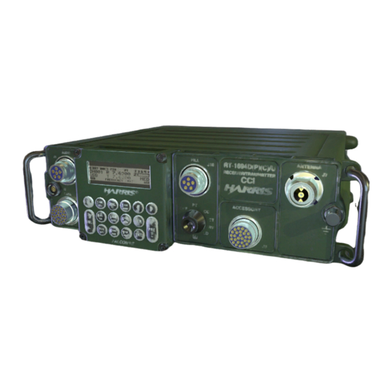
RF-5800H 125-WATT COMMUNICATION SYSTEM GENERAL INFORMATION RF-5800H-MP RF-5832H-PA BASE STATION TRANSIT CASE 5800H-125-V120A Figure 1-1. Typical RF-5800H 125-Watt Communication System... -
Page 16: Configuration
CAUTION – Paragraph 2.2.1.4 – Inadequate or defective grounding could damage the equipment. 1.3 MAINTENANCE LEVELS Harris/RF Communications designs its products and systems to be supported by up to four maintenance levels. See Figure 1-2. Each maintenance level relies on a defined set of support documentation and equipment in order to fulfill its maintenance tasks. - Page 17 Level IV. 1.3.4 Level IV The faulty SRU or module is returned to Harris/RF Communications for repair. If Level IV maintenance capabilities are available on-site, the maintenance technician can identify the faulty component on the SRU using a Depot Maintenance (Level IV) manual that outlines the electronic maintenance techniques and test fixtures...
- Page 18 RF-5800H 125-WATT COMMUNICATION SYSTEM GENERAL INFORMATION START NORMAL OPERATION LEVEL I SYSTEM REPAIRED OPERATIONAL SYSTEM TECHNICIAN SYSTEM REPLACES UNIT OPERATIONAL OR CABLE LEVEL II DEFECTIVE REPAIRED UNIT UNIT REPAIRED UNIT UNIT TECHNICIAN REPLACES OPERATIONAL MODULE LEVEL III DEFECTIVE MODULE LEVEL IV REPAIRED MODULE TECHNICIAN REPAIRS...
-
Page 19: Rf-5800H 125-Watt Configurations
Harris will repair or replace the equipment at no charge. Repairs made by Harris to the equipment under this warranty are warranted to be free from defects in material and workmanship for 60 days from the date of repair. -
Page 20: Related Equipment Manuals
RF-5800H 125-WATT COMMUNICATION SYSTEM GENERAL INFORMATION 1.5.4 Related Equipment Manuals Table 1-2 identifies the manuals that may be necessary to configure and maintain the RF-5800H 125-Watt Communication System in its various configurations. Table 1-2. Related Equipment Manuals Part Number Manual Description 10515-0008-4300 RF-382, CU-2397 Antenna Coupler Intermediate Maintenance Manual... -
Page 21: Relationship Of Units In Rf-5800H 125-Watt Vehicular System
RF-5800H 125-WATT COMMUNICATION SYSTEM GENERAL INFORMATION RF-5832H-PA 125-WATT POWER AMPLIFIER RF-5800H-MP MANPACK RADIO PA CONTROL CPLR CONTROL D.C. POWER RF IN RF OUT RF-5071VSM RF-5211VSM VEHICULAR SHOCK VEHICULAR SHOCK MOUNT MOUNT 5800H-125-VEH6 Figure 1-3. Relationship of Units in RF-5800H 125-Watt Vehicular System Typical Configuration... -
Page 22: Rf-5800H 125-Watt Vehicular System Family Tree
RF-5800H 125-WATT COMMUNICATION SYSTEM GENERAL INFORMATION RF-5800H-V004 125-WATT VEHICULAR ADAPTER RF-5832H-PA RF-5211VSM RF-5271VSM 125-WATT SHOCK MOUNT SHOCK MOUNT POWER AMPLIFIER RF-5211VSM RF-5071VSM RF-5832H-PA001 RF-5800H-125W CABLE ASSY, CABLE CABLE ASSY, CABLE ASSY COMMUNICATION RT-PA ASSY, PA-R/T GROUND SYSTEM INSTALLATION STRAP (RF) DC POWER CONTROL MANUAL... -
Page 23: Relationship Of Units In Rf-5800H 125-Watt Base Station System
RF-5800H 125-WATT COMMUNICATION SYSTEM GENERAL INFORMATION SPEAKER (10181-5180-01) RF-5800H-MP MANPACK RADIO (ORDERED SEPARATELY) RF-5051PS POWER SUPPLY BASE STATION RF-5832H-PA MOUNT POWER AMPLIFIER (10558-2000-02) 5800H-125-122 Figure 1-5. Relationship of Units in RF-5800H 125-Watt Base Station System Typical Configuration... -
Page 24: Rf-5800H 125-Watt Base Station System Family Tree
RF-5800H 125-WATT COMMUNICATION SYSTEM GENERAL INFORMATION RF-5800H-B004 125-WATT BASE STATION SYSTEM RF-5800H-125-W RF-5832H-PA SPEAKER, RF-5051PS-125 BASE COMMUNICATIONS FALCON II VEHICULAR 125-WATT STATION SYSTEM INSTALLATION 125W PA MOUNTED POWER SUPPLY MOUNT MANUAL RF-5832H-PA001 10181-5180-01 10299-5051-03 10558-2000-02 10515-0124-4200 CABLE ASSY, CABLE CABLE ASSY, SPEAKER SPEAKER RT-PA... -
Page 25: Typical Configuration
RF-5800H 125-WATT COMMUNICATION SYSTEM GENERAL INFORMATION LOUDSPEAKER (10181-5180-01) 1 A BC 3 G HI R/T TRANSIT CASE CALL MODE 4 JKL ZERO 7 S TU – OPT – RF-5800H-MP MANPACK RADIO (ORDERED SEPARATELY) PS/PA TRANSIT CASE +28 VDC AC IN 95–150 VAC 187–300 VAC P.A. -
Page 26: Rf-5800H 125-Watt Transit Case System Family Tree Typical
RF-5800H 125-WATT COMMUNICATION SYSTEM GENERAL INFORMATION RF-5800H-TM004 125-WATT TRANSIT CASE SYSTEM RF-5832H-PA SPEAKER, RF-5051PS-125 TRANSIT TRANSIT FALCON II VEHICULAR 125-WATT CASE, CASE, 125W PA MOUNTED POWER SUPPLY R/T ASSEMBLY PA/PS ASSEMBLY RF-5832H-PA001 10181-5180-01 10299-5051-03 11040-1100-01 10400-0561-01 CABLE ASSY, CABLE CABLE ASSY, SPEAKER SPEAKER RT-PA... - Page 27 RF-5800H 125-WATT COMMUNICATION SYSTEM GENERAL INFORMATION 1.6 GENERAL EQUIPMENT DESCRIPTIONS The following paragraphs describe the units that make up the RF-5800H 125-Watt Communication System. 1.6.1 RF-5832H-PA The RF-5832H-PA responds to control inputs from the RF-5800H-MP and is operator transparent. It requires either a separate antenna coupler such as the RF-382A or a 50-ohm broadband antenna.
-
Page 28: Required Tools, Test Equipment, And Materials
1.8 LIST OF MANUFACTURERS Table 1-4 provides a list of manufacturers. Table 1-4. List of Manufacturers CAGE Code Manufacturer Name and Address 14304 Harris Corporation RF Communications Division 1680 University Avenue Rochester, NY 14610-2842 55719 Snap-On Tools 2801 80th Street... - Page 29 RF-5800H 125-WATT COMMUNICATION SYSTEM GENERAL INFORMATION This page intentionally left blank. 1-14...
- Page 30 RF-5800H 125-WATT COMMUNICATION SYSTEM INSTALLATION CHAPTER 2 INSTALLATION 2.1 INTRODUCTION This chapter describes the following: • Site information – Paragraph 2.2 • Tools and materials required – Paragraph 2.3 • Unpacking and repacking – Paragraph 2.4 • Equipment installation – Paragraph 2.5 •...
- Page 31 RF-5800H 125-WATT COMMUNICATION SYSTEM INSTALLATION 2.2.1.2 Vehicular Configuration Grounding The following are general guidelines for vehicular grounding: • All ground straps should be as short as possible (ideally less than 12 inches [30 cm]). NOTE This system is grounded by connecting power ground return directly to the power source ground to maximize noise immunity.
- Page 32 Certain boxes, depending on system configuration, may be heavy. Exercise care when moving boxed assemblies to and from locations. After removing the equipment from the box, check the contents against the packing slip to see that the shipment is complete. Report discrepancies to Harris/RF Communications’ customer service department (tel: 716-244-5830). 2.4.2 Repacking Perform the following procedure to repack the equipment: Use the original box if it was retained.
- Page 33 RF-5800H 125-WATT COMMUNICATION SYSTEM INSTALLATION 2.5 EQUIPMENT INSTALLATION The following paragraphs describe the power requirements and ancillary items kit required to properly install the radio system. Cabling, switch settings, unit removal and installation procedures, clearance and ventilation requirements, and mounting information is also included. For installation information regarding the RF-5056PS 12/24 V DC/DC Power Converter or RF-382A refer to their applicable manuals listed in Table 1-2.
- Page 34 RF-5800H 125-WATT COMMUNICATION SYSTEM INSTALLATION Add a ground strap at one of the four locations between the lockwasher and the shock mount bottom plate. For the four hole locations on the RF-5211VSM, attach to the vehicle in the following arrangement: •...
- Page 35 RF-5800H 125-WATT COMMUNICATION SYSTEM INSTALLATION This page intentionally left blank.
-
Page 36: Rf-5800H-125 Watt Base Station Installation And Maintenance
RF-5800H 125-WATT COMMUNICATION SYSTEM INSTALLATION 3 IN 14 IN 3 IN 1.5 IN 17.7 IN 20.7 IN 3 IN 5800H-125-126A Figure 2-2. RF-5800H-125 Watt Base Station Installation and Maintenance Clearances... -
Page 37: Rf-5800H-125 Watt Transit Case Installation And Maintenance
RF-5800H 125-WATT COMMUNICATION SYSTEM INSTALLATION 3 IN 15 IN 15 IN 3 IN 3 IN 22.5 IN 18.75 IN 3 IN Figure 2-3. RF-5800H-125 Watt Transit Case Installation and Maintenance Clearances 2-10... -
Page 38: Rf-5071Vsm Shock Mount Dimensions
RF-5800H 125-WATT COMMUNICATION SYSTEM INSTALLATION 2 IN 12.25 IN 7.75 IN 0.75 IN 6.25 IN 0.75 IN 10.75 IN 5800H-125VEH8 Figure 2-4. RF-5071VSM Shock Mount Dimensions 2-11... -
Page 39: Rf-5211Vsm Shock Mount Dimensions
RF-5800H 125-WATT COMMUNICATION SYSTEM INSTALLATION 5.25 IN 10.75 IN 8.75 IN 3.94 IN 3.41 IN 2 IN 4.75 IN 5800H-125VEH9 Figure 2-5. RF-5211VSM Shock Mount Dimensions 2-12... -
Page 40: Rf-5211-01Vsm Shock Mount Dimensions
RF-5800H 125-WATT COMMUNICATION SYSTEM INSTALLATION 5.25 IN 10.75 IN 8.75 IN 4 IN 3.5 IN 2 IN 4.75 IN RF-5800H-507 Figure 2-6. RF-5211-01VSM Shock Mount Dimensions 2-13... - Page 41 RF-5800H 125-WATT COMMUNICATION SYSTEM INSTALLATION This page intentionally left blank. 2-14...
-
Page 42: Rf-5800H 125-Watt Vehicular System Cable Interconnects
RF-5800H 125-WATT COMMUNICATION SYSTEM INSTALLATION HANDSET (H-250/U) (10075-1399) R/T-PA RF CABLE ASSY RF-5800H-MP (10181-9821) MANPACK RADIO R/T-PA CONTROL CABLE (10535-0720) RF-382A RF-5832H-PA ANTENNA COUPLER POWER AMPLIFIER PA-COUPLER CONTROL CABLE (10181-9823) GROUND PA-COUPLER COAXIAL CABLE RF-5832H-PA (10181-9825 OR 10181-9824) DC POWER CABLE (10181-9826) BATTERY ALTERNATOR POWER SYSTEM... -
Page 43: Rf-5800H 125-Watt Base Station Or Transit Case System Cable
RF-5800H 125-WATT COMMUNICATION SYSTEM INSTALLATION SPEAKER (10181-5180-01) HANDSET R/T-PA (H-250/U) COAX CABLE (10075-1399) SPEAKER CABLE ASSEMBLY (10181-9821) (10535-0707) RF-5800H-MP MANPACK RADIO GROUND R/T – PA CONTROL CABLE (10535-0720) RF-382A ANTENNA COUPLER RF-5832H-PA POWER AMPLIFIER P.A. CONTROL CPLR CONTROL D.C. POWER RF IN RF OUT PA TO COUPLER... -
Page 44: Antenna Considerations
RF-5800H 125-WATT COMMUNICATION SYSTEM INSTALLATION 2.5.7 Antenna Considerations A number of factors should be considered before erecting an antenna. Radio signals are absorbed and reflected by nearby obstructions such as hills, trees, buildings, and power lines. Avoid these if possible, especially when they are in a direct line with the RF signal path. - Page 45 RF-5800H 125-WATT COMMUNICATION SYSTEM INSTALLATION Press the ENT pushbutton. If necessary, press the left/right arrow pushbuttons to select the ALL field. Press the ENT pushbutton. If the unit passes BIT, place in service. If a BIT code is displayed refer to the following paragraphs. If the RF-5800H-MP displays a fault code on the LCD after completing the BIT test, record the fault code and proceed to Paragraph 6.2.4, BIT Troubleshooting.
-
Page 46: Chapter 3 - Operation
RF-5800H 125-WATT COMMUNICATION SYSTEM OPERATION CHAPTER 3 OPERATION There are no special operating procedures at Level II maintenance. Refer to Paragraph 6.2.2 for a Level II operational check. For normal operation, refer to the RF-5800H-MP Operations Manual listed in Table 1-2. - Page 47 RF-5800H 125-WATT COMMUNICATION SYSTEM OPERATION This page intentionally left blank.
-
Page 48: Chapter 4 - Functional Description
RF-5800H 125-WATT COMMUNICATION SYSTEM FUNCTIONAL DESCRIPTION CHAPTER 4 FUNCTIONAL DESCRIPTION 4.1 INTRODUCTION This chapter covers the functional description of the RF-5800H 125-Watt Communication System. Refer to Chapter 6 for BIT and system troubleshooting information. The major function level description is divided into the following three signal paths: •... -
Page 49: Rf-5800H 125-Watt Vehicular System
RF-5800H 125-WATT COMMUNICATION SYSTERM FUNCTIONAL DESCRIPTION 4.2.3.1 RF-5800H 125-Watt Vehicular System See Figure 4-2. Power distribution for the RF-5800H 125-Watt Vehicular System consists of distributing +28 Vdc nominal voltage from the vehicle alternator/battery system to the various units in the system. External power enters the RF-5832H-PA at connector J10. - Page 50 RF-5800H 125-WATT COMMUNICATION SYSTEM FUNCTIONAL DESCRIPTION...
-
Page 51: Vehicular Power Distribution Diagram
RF-5800H 125-WATT COMMUNICATION SYSTERM FUNCTIONAL DESCRIPTION ACCESSORY R/T 28V RTN R/T 28V RTN +28 V SWITCHED +28 VDC +28 V SWITCHED +28 VDC RF-5800H-MP RF-5832H-PA RF-382A (OPTIONAL) A B C D E J10 5800H-VEH05 TO +28 VDC VEHICULAR ALTERNATOR/BATTERY SYSTEM Figure 4-2. -
Page 52: Base Station Or Transmit Case System Power Distribution Diagram
RF-5800H 125-WATT COMMUNICATION SYSTEM FUNCTIONAL DESCRIPTION RF-5800H-MP RF-5832H-PA MANPACK RADIO 125-WATT POWER AMPLIFIER 10535-0720 EXT. PA ON / OFF PA POWER ON R/T 28V RTN 28V RTN 28V RTN R/T 28V RTN +28 VDC +28 VDC +28 VDC +28 VDC +28V SWITCHED TO COUPLER +28V SWITCHED... - Page 53 RF-5800H 125-WATT COMMUNICATION SYSTERM FUNCTIONAL DESCRIPTION This page intentionally left blank.
-
Page 54: Chapter 5 - Scheduled Maintenance
RF-5800H 125-WATT COMMUNICATION SYSTEM SCHEDULED MAINTENANCE CHAPTER 5 SCHEDULED MAINTENANCE 5.1 PREVENTIVE MAINTENANCE Preventive maintenance is the systematic, daily care and inspection of equipment to prevent equipment failure and reduce downtime. Table 5-1 contains the checks and services that should either be performed on a daily basis when the equipment is in use or on a weekly basis when the equipment is in a standby condition. - Page 55 RF-5800H 125-WATT COMMUNICATION SYSTEM SCHEDULED MAINTENANCE This page intentionally left blank.
-
Page 56: Chapter 6 - Troubleshooting
RF-5800H 125-WATT COMMUNICATION SYSTEM TROUBLESHOOTING CHAPTER 6 TROUBLESHOOTING 6.1 INTRODUCTION 6.1.1 General This chapter provides troubleshooting data necessary for fault isolation to the LRU level. 6.1.2 Scope of this Chapter See Figure 6-1. The procedures presented in this chapter assume that a Level I fault has led the maintainer to suspect a fault with the RF-5800H 125-Watt Communication System. -
Page 57: Troubleshooting Procedures
RF-5800H 125-WATT COMMUNICATION SYSTEM TROUBLESHOOTING 6.2 TROUBLESHOOTING PROCEDURES 6.2.1 General Troubleshooting begins with performing the maintenance turn-on procedure. The maintenance turn-on procedure references the non-BIT and BIT troubleshooting procedures. 6.2.2 Maintenance Turn-On Procedure The maintenance turn-on procedure is used to guide the maintainer through the proper RF-5800H-MP front panel settings to power up the RF-5800H 125-Watt Communication System from a de-energized state to a fully operational state. -
Page 58: Non-Bit Troubleshooting
RF-5800H 125-WATT COMMUNICATION SYSTEM TROUBLESHOOTING 6.2.3 Non-BIT Troubleshooting Table 6-1 is a list of the non-BIT fault symptoms. Next to the symptom is a reference to the recommended action that should be taken. Perform the recommended actions one at a time in the order listed, testing the system after each action is performed. - Page 59 RF-5800H 125-WATT COMMUNICATION SYSTEM TROUBLESHOOTING Table 6-1. Non-BIT Fault Symptoms/Run Time Fault Codes – Continued Symptom Observed Action PA LOW DC INPUT displayed on RF-5800H-MP KDU. Perform the following: • Check that DC input voltage is within specification. Perform check under both a loaded and unloaded condition.
- Page 60 RF-5800H 125-WATT COMMUNICATION SYSTEM TROUBLESHOOTING Table 6-1. Non-BIT Fault Symptoms/Run Time Fault Codes – Continued Symptom Observed Action Variable or no audio signals. Perform the following: • Check PA-R/T audio cable and replace as necessary. • Replace RF-5800H-MP. • Replace RF-5832H-PA. Accessory connected to RF-5832H-PA does not power up.
-
Page 61: Bit Troubleshooting
RF-5800H 125-WATT COMMUNICATION SYSTEM TROUBLESHOOTING 6.2.4 BIT Troubleshooting BIT is executed from the KDU of the RF-5800H-MP connected to the RF-5800H 125-Watt Communication System, or from an optional terminal connected to the RF-5800H-MP. The self-test function of the RF-5800H-MP automatically tests the system. If a problem is located, a fault code is displayed on the KDU display. See Figure 6-2 for a sample fault code displayed on the KDU. -
Page 62: Taps
RF-5800H 125-WATT COMMUNICATION SYSTEM TROUBLESHOOTING 6.2.5 TAPs TAPs are provided to help the maintainer isolate faults using procedures other than simple unit swapping. The TAP begins with a simple description of the fault or symptom. Refer to Table 6-3 for a list of TAPs. When applicable, begin by performing the listed initial checks. - Page 63 RF-5800H 125-WATT COMMUNICATION SYSTEM TROUBLESHOOTING TAP-1: NO POWER UP (VEHICULAR) Does system power up? RF-5800H 125-Watt Vehicular System does not power up. INITIAL CHECKS Remove replace RF-5800H-MP. Return system to operational readiness. Make sure all cables are connected. Return system to operational readiness. Make sure all units are properly seated.
- Page 64 RF-5800H 125-WATT COMMUNICATION SYSTEM TROUBLESHOOTING TAP-2: NO POWER UP (BASE STATION OR TRANSIT CASE Check RF-5051PS DC output voltage at the output of DC Power Cable Assembly, (10181-9833) connected to J10 on SYSTEM) the RF-5832H-PA. Is DC voltage present? RF-5800H 125-Watt System does not power up. INITIAL CHECKS Remove and replace DC Power Cable Assembly, (10181-9832).
-
Page 65: Troubleshooting Support Data
RF-5800H 125-WATT COMMUNICATION SYSTEM TROUBLESHOOTING 6.3 TROUBLESHOOTING SUPPORT DATA 6.3.1 Protective Device Index Table 6-4 is the protective device index. The RF-5832H-PA is protected by one 30-ampere circuit breaker. The circuit breaker, CB1, is accessible at the front panel of the power amplifier. The circuit breaker protects both the power amplifier and RF-5800H-MP. -
Page 66: Troubleshooting Diagrams
RF-5800H 125-WATT COMMUNICATION SYSTEM TROUBLESHOOTING 6.4 TROUBLESHOOTING DIAGRAMS 6.4.1 General Troubleshooting diagrams include the following: • RF Signal Path Diagram – See Figure 4-1 for RF signals diagram. • Control Path Diagram – See Figure 4-1 for control and data signals diagram. •... - Page 67 RF-5800H 125-WATT COMMUNICATION SYSTEM TROUBLESHOOTING This page intentionally left blank. 6-12...
-
Page 68: Rf-5800H 125-Watt Vehicular System Lrus
RF-5800H 125-WATT COMMUNICATION SYSTEM PARTS LIST CHAPTER 7 PARTS LIST 7.1 INTRODUCTION This chapter contains radio system parts list information for the RF-5800H 125-Watt Communication System. This information can be used to identify units within each radio system configuration, and to place orders for those units. -
Page 69: Rf-5800H 125-Watt Transit Case System Lrus
RF-5800H 125-WATT COMMUNICATION SYSTEM PARTS LIST Table 7-3. RF-5800H 125-Watt Transit Case System LRUs Part Figure Ref. Des. Item Name Quantity Number Number – RF-5832H-PA 125-Watt Power Amplifier RF-5832H-PA001 RF-5051PS-125 Power Supply 10299-5051-03 Speaker, Vehicular Mount 10181-5180-01 Coaxial Cable Assembly, R/T-PA (RF) 10181-9821-015 Cable Assembly, AC PWR 10181-9831-009... -
Page 70: Rf-5051Ps Ancillary Kit Parts List
RF-5800H 125-WATT COMMUNICATION SYSTEM PARTS LIST Table 7-7. RF-5211VSM Ancillary Kit Parts List (10372-0875-01) Part Figure Ref. Des. Item Name Quantity Number Number – FW SS .281X.625 MS15795-810 – – FW SS .344X.688 MS15795-812 – – Bolt Hex HD 1/4-20X1 MS35307-308 –... -
Page 71: Available Option Cables (Purchased Separately)
RF-5800H 125-WATT COMMUNICATION SYSTEM PARTS LIST Table 7-11. Available Option Cables (Purchased Separately) Part Figure Ref. Des. Item Name Quantity Number Number – Cable Assembly, PA-Coupler (Control) 10181-9823 – – 7-13 – Cable Assembly, PA-Coupler (RF) 10181-9824 – – 7-12 –... - Page 72 RF-5800H 125-WATT COMMUNICATION SYSTEM PARTS LIST 5800H–125W-133 Figure 7-1. RF-5832H-PA 125-Watt Power Amplifier...
- Page 73 RF-5800H 125-WATT COMMUNICATION SYSTEM PARTS LIST 5800H-400-322 Figure 7-2. RF-5051PS Power Supply...
-
Page 74: Rf-5071Vsm Shock Mount Assembly
RF-5800H 125-WATT COMMUNICATION SYSTEM PARTS LIST 5800H–125W-134 Figure 7-3. RF-5071VSM Shock Mount Assembly... -
Page 75: Rf-5211Vsm Shock Mount Assembly
RF-5800H 125-WATT COMMUNICATION SYSTEM PARTS LIST 5800H–125W-135 Figure 7-4. RF-5211VSM Shock Mount Assembly... -
Page 76: Rf-5211-01Vsm Shock Mount Assembly
RF-5800H 125-WATT COMMUNICATION SYSTEM PARTS LIST 5800H–505 Figure 7-5. RF-5211-01VSM Shock Mount Assembly... -
Page 77: Typical Configuration
RF-5800H 125-WATT COMMUNICATION SYSTEM PARTS LIST 5800H–125W-136 Figure 7-6. RF-5800H-125 Watt Base Station Mount Assembly Typical Configuration 7-10... -
Page 78: Typical Configuration
RF-5800H 125-WATT COMMUNICATION SYSTEM PARTS LIST 5800H–125W-137A Figure 7-7. RF-5800H-125 Watt Transit Case Mount Assembly Typical Configuration 7-11... -
Page 79: R/T-Pa Coaxial Cable Assembly
RF-5800H 125-WATT COMMUNICATION SYSTEM PARTS LIST 10181-9821-XXX 10181-9821-XXX R/T-P.A. (RF) R/T-P.A. (RF) 20 FT. Figure 7-8. R/T-PA Coaxial Cable Assembly (10181-9821) 19 FT. 10 IN 1 IN Ç Ç Ç Ç TO PA 10181-9826-020 D.C. POWER Ç Ç Ç Ç 5KS-055A Ç... -
Page 80: Ac Power Cable Assembly (10181-9831)
RF-5800H 125-WATT COMMUNICATION SYSTEM PARTS LIST Figure 7-11. AC Power Cable Assembly (10181-9831 Rev. D) Figure 7-12. PA-Coupler RF Cable Assembly (10181-9824 Rev. E) 7-15... - Page 81 RF-5800H 125-WATT COMMUNICATION SYSTEM PARTS LIST This page intentionally left blank. 7-16...
- Page 82 RF-5800H 125-WATT COMMUNICATION SYSTEM PARTS LIST 5800H–125-146 Figure 7-22. DC Power Cable Assembly (10181-9833) 7-37...
-
Page 83: Speaker Power Cable Assembly
RF-5800H 125-WATT COMMUNICATION SYSTEM PARTS LIST 5800H–125-147 Figure 7-23. Speaker Power Cable Assembly (10535-0706) 7-38... -
Page 84: Speaker Cable Assembly
RF-5800H 125-WATT COMMUNICATION SYSTEM PARTS LIST 5800H–125-148 Figure 7-24. Speaker Cable Assembly (10535-0707) 7-39... -
Page 85: Ground Strap Cable Assembly
RF-5800H 125-WATT COMMUNICATION SYSTEM PARTS LIST 5800H–125-149 Figure 7-25. Ground Strap Cable Assembly (10400-1136) 7-40... -
Page 86: General
RF-5800H 125-WATT COMMUNICATION SYSTEM APPENDIX A APPENDIX A A.1 TECHNICAL SPECIFICATIONS Table A-1 provides RF-5832H-PA specifications. Tables A-2, A-3, and A-4 provide specifications for the RF-5051PS, RF-382A, and the RF-5056PS DC/DC Power Converter. Table A-1. RF-5832H-PA Specifications Function Specification GENERAL Frequency Range 1.6 MHz to 29.99999 MHz RF Input/Output Impedance... - Page 87 RF-5800H 125-WATT COMMUNICATION SYSTEM APPENDIX A Table A-2. RF-5051PS Specifications – Continued Function Specification ° ° Temperature Range –40 C to +70 Shock/Vibration MIL-STD-810D Table A-3. RF-382A Specifications Function Specification GENERAL Rated RF Input Power, Frequency Up to 500 watts PEP Range, and Tuning Capability 1.5 to 30 MHz: 75- to 150-ft.
- Page 88 RF-5800H 125-WATT COMMUNICATION SYSTEM APPENDIX A Table A-3. RF-382A Specifications – Continued Function Specification MIL-STD-167-1 Type I (sinusoidal resonance search) for shipboard equipment SHOCK MIL-STD-810E Method 516.3, procedure I (functional shock) for ground mobile equipment (40 G, 11 ms sawtooth); procedure VI (bench handling shock) for equipment experiencing bench-type maintenance Temperature MIL-STD-810E, Method 501.2, procedures I and II (storage at 70°...
- Page 89 RF-5800H 125-WATT COMMUNICATION SYSTEM APPENDIX A This page intentionally left blank.
- Page 90 RF-5800H 125-WATT COMMUNICATION SYSTEM GLOSSARY GLOSSARY Ancillary Interface Connector Altitude Antenna American Wire Gauge Built-In Test CAGE Commercial and Government Entity Collocation Placing or arranging systems in close proximity of each other. Configuration The process of setting parameter values which define the current hardware setup and/or operational modes.
- Page 91 RF-5800H 125-WATT COMMUNICATION SYSTEM GLOSSARY GLOSSARY – Continued Display An electronic device which produces visible output (in non-permanent form). The output may take the form or text, graphics, or a combination of the two. Digital Signal Processor Data Transmission Equipment Data Terminal Ready DV (Digital Voice) Analog voice that has been converted into a digital data...
- Page 92 RF-5800H 125-WATT COMMUNICATION SYSTEM GLOSSARY GLOSSARY – Continued INFOSEC Information Security Processor Interrupt Request Keypad Display Unit Abbreviation for kilohertz, or thousands of cycles per second. Liquid Crustal Display Latitude Load Longitude LPC (Linear Predictive Coding) A technique used to generate digital voice. Line Replaceable Unit (Units in this manual.) Light Menu...
- Page 93 RF-5800H 125-WATT COMMUNICATION SYSTEM GLOSSARY GLOSSARY – Continued NCS (Net Control Station) The station in the radio net that has radio control over net members. Non-Volatile Options Power Amplifier Parameter Data provided to a program to alter its function in some manner defined by that program.
- Page 94 RF-5800H 125-WATT COMMUNICATION SYSTEM GLOSSARY GLOSSARY – Continued Radio Configuration Data describing a radio including name, description, etc. Random Access Memory Radio Frequency Read-Only Memory Receiver-Transmitter Real-Time Clock Receive Variable Receive Start Of Message SPCM Signal Processing Core Module Squelch SRAM Static RAM Shop Replaceable Unit...
- Page 95 RF-5800H 125-WATT COMMUNICATION SYSTEM GLOSSARY GLOSSARY – Continued Vehicular Intercom System Volume VRCS Vehicular Radio Communications System ZERO Zeroize Zeroize A command sequence which erases all programmed radio configuration information...
- Page 96 EVALUATION FORM To the User of this Instruction Manual: HARRIS Corporation, RF Communications Division continually evaluates its technical publications for completeness, technical accuracy, and organization. You can assist in this process by completing and returning this form. Please specify section, page number, figure or table number where applicable.
- Page 97 NO POSTAGE NECESSARY IF MAILED IN THE UNITED STATES BUSINESS REPLY MAIL FIRST CLASS PERMIT NO. 4033 ROCHESTER, N.Y. POSTAGE WILL BE PAID BY ADDRESSEE HARRIS CORPORATION RF COMMUNICATIONS DIVISION 1680 UNIVERSITY AVENUE ROCHESTER, NEW YORK 14610-1887 ATTN: TECHNICAL SERVICES...
- Page 98 RF Communications Division ½ 1680 University Ave ½ Rochester, NY USA 14610 Tel: 716-244-5830. Fax: 716-242-4755 www.harris.com...
-
Page 99: Rf-5800H 125-Watt Vehicular System Installation And Maintenance Clearances
RF-5800H 125-WATT COMMUNICATION SYSTEM INSTALLATION 1.5 IN 1.5 IN 5.25 IN 7 IN 1.5 IN 1.5 IN 1.5 IN 11.5 IN 11 IN 1.5 IN 14 IN 7.75 IN 1.5 IN 1.5 IN 5800H-125VEH11A Figure 2-1. RF-5800H 125-Watt Vehicular System Installation and Maintenance Clearances 2-7/2-8... -
Page 100: Rf-5800H 125-Watt Vehicular System Installation Typical
RF-5800H 125-WATT COMMUNICATION SYSTEM INSTALLATION TIGHTEN WING NUTS (2 PLACES) TIGHTEN WING NUT 5800H-125VEH10 Figure 2-7. RF-5800H 125-Watt Vehicular System Installation Typical Configuration 2-15/2-16... -
Page 101: Typical Configuration
RF-5800H 125-WATT COMMUNICATION SYSTEM INSTALLATION SLIDE RF-5800H-MP INTO BASE STATION MOUNT AND TIGHTEN WING NUTS SLIDE POWER SUPPLY RF-5051PS INTO BASE STATION MOUNT PLACE SPEAKER ON MOUNT AND TIGHTEN WING NUT TIGHTEN WING NUT SLIDE RF-5832H-PA INTO TIGHTEN BASE STATION MOUNT WING NUT PLACE BASE STATION MOUNT INTO POSITION... -
Page 102: Rf-5800H 125-Watt Transit Case System Installation
RF-5800H 125-WATT COMMUNICATION SYSTEM INSTALLATION CONNECT CABLES (SEE FIGURE 2-11). SLIDE RF-5800H-MP INTO TRANSIT CASE MOUNT TIGHTEN WING NUT SLIDE POWER SUPPLY RF-5051PS INTO TRANSIT CASE MOUNT SLIDE RF-5832H-PA INTO TRANSIT CASE MOUNT PLACE TRANSIT CASES INTO POSITION TIGHTEN WING NUT 5800H-125-129A TIGHTEN WING NUT... -
Page 103: Pa-R/T Cable Assembly (10535-0720)
RF-5800H 125-WATT COMMUNICATION SYSTEM PARTS LIST 5800H–125-138 Figure 7-10. PA-R/T Cable Assembly (10535-0720 Rev. B) 7-13/7-14... -
Page 104: Pa-Coupler Control Cable Assembly (10181-9823)
RF-5800H 125-WATT COMMUNICATION SYSTEM PARTS LIST 5800H–125-138 Figure 7-13. PA-Coupler Control Cable Assembly (10181-9823 Rev. E) 7-17/7-18... -
Page 105: Ky-99A Audio/Black Data Cable Assembly (10535-0701)
RF-5800H 125-WATT COMMUNICATION SYSTEM PARTS LIST 5800H–125-140 Figure 7-14. KY-99A Audio/Black Data Cable Assembly (10535-0701 Rev. A) 7-19/7-20... -
Page 106: Black Data To Encryption Device Cable Assembly (10535-0702)
RF-5800H 125-WATT COMMUNICATION SYSTEM PARTS LIST 5800H–125-141 Figure 7-15. RS-232 Black Data to Encryption Device Cable Assembly (10535-0702 Rev. A) (Sheet 1 of 2) 7-21/7-22... - Page 107 RF-5800H 125-WATT COMMUNICATION SYSTEM PARTS LIST A1E22 5800H–125-142 Figure 7-15. RS-232 Black Data to Encryption Device Cable Assembly (10535-0702 Rev. A) (Sheet 2 of 2) 7-23/7-24...
-
Page 108: Ascii Remote And Ps Control Cable Assembly, Y (10535-0730)
RF-5800H 125-WATT COMMUNICATION SYSTEM PARTS LIST 5800H–125-143 Figure 7-16. ASCII Remote and PS Control Cable Assembly, Y (10535-0730 Rev. –) 7-25/7-26... -
Page 109: Kg-84C Black Data Cable Assembly, Y (10535-0750)
RF-5800H 125-WATT COMMUNICATION SYSTEM PARTS LIST 5800H–125-143 Figure 7-17. KG-84C Black Data Cable Assembly, Y (10535-0750 Rev. –) 7-27/7-28... - Page 110 RF-5800H 125-WATT COMMUNICATION SYSTEM PARTS LIST 5800H–125-144 – Figure 7-18. ASCII Remote Control Rear D-Connenctor Cable Assembly (10535-0760 Rev. –) 7-29/7-30...
-
Page 111: Sync/Async Rs-232 Dte Data Cable Assembly (10535-0770)
RF-5800H 125-WATT COMMUNICATION SYSTEM PARTS LIST Figure 7-19. Sync/Async RS-232 DTE Data Cable Assembly (10535-0770 Rev. –) 7-31/7-32... - Page 112 RF-5800H 125-WATT COMMUNICATION SYSTEM PARTS LIST 5800H–125-145 Figure 7-20. Synchronous RS-232 DTE Data Cable Assembly (10535-0780 Rev. –) 7-33/7-34...
-
Page 113: Asynchronous Data (Ppp) Cable Assembly
RF-5800H 125-WATT COMMUNICATION SYSTEM PARTS LIST Figure 7-21. Asynchronous Data (PPP) Cable Assembly (10535-0775 Rev. –) 7-35/7-36... - Page 114 PUBLICATION NUMBER: 10515-0124-4200 FEBRUARY 2001 Rev. A Tactical Radio Products RF-5800H 125-WATT COMMUNICATION SYSTEM SYSTEM INSTALLATION/ MAINTENANCE MANUAL next level solutions...
Need help?
Do you have a question about the RF-5800H Series and is the answer not in the manual?
Questions and answers