Table of Contents
Advertisement
Quick Links
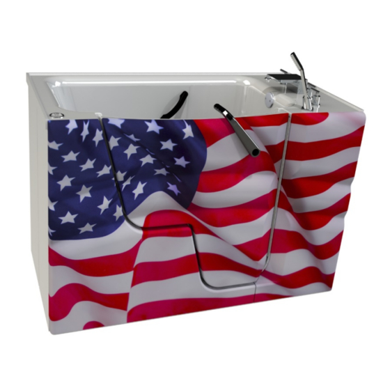
Dream Spa with Aqua-Aire
Installation / Assembly Instructions
760010-1, 760010-2, 770010-1, 770010-2
PENNER PATIENT CARE, INC
Box 523 / 101 Grant St.
Aurora, NE 68818
760745 Revision A – 10/2/2019
1-866-PENNERS
1-866-736-6377
1-800-732-0717
E-mail Address:
pennersales@Hamilton.net
Web Site:
www.pennerbathingspas.com
Advertisement
Table of Contents

Summary of Contents for Penner Bathing Spas Dream Spa 760010-1
- Page 1 Dream Spa with Aqua-Aire Installation / Assembly Instructions 760010-1, 760010-2, 770010-1, 770010-2 PENNER PATIENT CARE, INC Box 523 / 101 Grant St. Aurora, NE 68818 760745 Revision A – 10/2/2019 1-866-PENNERS 1-866-736-6377 1-800-732-0717 E-mail Address: pennersales@Hamilton.net Web Site: www.pennerbathingspas.com...
-
Page 2: Table Of Contents
Table of Contents Table of Contents Introduction Terminology and Symbols Meanings Tub Controls Basic Dimensions Rough in Specifications Drain Locations Hot and Cold Water Supply Requirements Electrical Requirements Unpacking the Tub Water Supply Hose Connections Anchoring the Tub Electrical Connections Water Supply and Drain Connections Finishing up... -
Page 3: Introduction
Introduction These instructions are for the installation of a Dream Spa tub in various configurations as shown below in figure 1. Follow the instructions for your particular installation configuration. Figure 1 Terminology and Symbols Meanings When the terms “left” or “right” are used with reference to the tub, this means left or right as you look when seated in the tub. -
Page 4: Tub Controls
Tub Controls Hot Temp Control Aqua-Aire High/med/low/off Cold Temp Control Tub Fill Diverter Valve (switch between tub fill and shower wand) Temperature Gauges Tub Fill Temp Shower Wand Temp Shower Wand Figure 2 The hot and cold temperature controls adjust the tub fill overall temperature. Hot temp is limited to 110°F from the factory. -
Page 5: Basic Dimensions
Basic Measurements Figures 3-6... -
Page 6: Rough In Specifications
Rough-in Specifications Figures 7-9... -
Page 7: Drain Locations
Drain Locations Figures 10-11 Figures 12-13... -
Page 8: Hot And Cold Water Supply Requirements
Hot and Cold water supply requirements ¾” supply lines with on/off valves NPT male threads. We recommend a ¾” ball valve with ¾” NPT male ports. (Valves supplied by others.) See figure 14-15 For optimum performance, dynamic pressures should be nominally equal between hot and cold supplies. -
Page 9: Unpacking The Tub
The blower motor sits on composite board. If drain, water supply, or electrical hook up are in this area, the board can be moved. Use a ½” wrench or socket and ratchet to remove the hold down nuts. Lift the board up and move to desired location while making sure the blower motor delivery hose doesn’t kink. -
Page 10: Anchoring The Tub
Anchoring the tub This anchoring procedure describes the steps for anchoring the in both positions as shown in Figure 1 under “Dream Spa Introduction”. 1. Ensure that the electrical supply box has been wired properly. Also ensure that the provided supply lines have been connected to the supply valves. 2. -
Page 11: Electrical Connections
Electrical Connections It is highly recommended that the electrical outlet be installed by a professional electrician. A minimum of a 15 amp 120 volt service is required with a ground fault circuit interrupter. Warning: Ensure that the power supply is turned off before attempting to wire in the power supply to the tub. -
Page 12: Finishing Up
Finishing up If removal of the fascia pieces or access doors was necessary during installation, reinstall those components. Apply a white silicon caulking between door cover and door. Wipe off excess amount with damp towel or clothe. Fascia screws need to be tightened enough to hold fascia in place, but DO NOT over tighten, as this may cause the fiberglass to crack.


Need help?
Do you have a question about the Dream Spa 760010-1 and is the answer not in the manual?
Questions and answers