Table of Contents
Advertisement
Quick Links
Doc. CEI12166
Istrumentazioni Sistemi Automatici S.r.l.
VIA BERGAMO 41 - 21020 TAINO (VA) - ITALY
OFFICES
TEL. +39.0331.956081 - FAX +39.0331.957091
LAB:
TEL. +39.0331.956483 -
E-MAIL
isa@isatest.com
WEB
www.isatest.com
DATE: 12/12/2005
CBA1000
INTRODUCTORY GUIDE
Rev. 1
DOC.MIE12166
Pag. 1 Of 47
REV.1
Advertisement
Table of Contents

Related Manuals for ISA CBA1000


Summary of Contents for ISA CBA1000
- Page 1 Doc. CEI12166 Rev. 1 Pag. 1 Of 47 Istrumentazioni Sistemi Automatici S.r.l. VIA BERGAMO 41 - 21020 TAINO (VA) - ITALY OFFICES TEL. +39.0331.956081 - FAX +39.0331.957091 LAB: TEL. +39.0331.956483 - E-MAIL isa@isatest.com www.isatest.com DATE: 12/12/2005 DOC.MIE12166 REV.1 CBA1000 INTRODUCTORY GUIDE...
-
Page 2: Table Of Contents
Doc. CEI12166 Rev. 1 Pag. 2 Of 47 SHORT FOREWORD ................................4 1 INTRODUCTION ................................5 2 TEST SET EXPLANATION ...............................7 2.1 T ........................7 HE FRONT PANEL AND THE KEY COMPONENTS 2.2 P ......................9 USHBUTTONS DISPLAY KEYPAD CONTROL KNOB 2.3 T ..............................9 HE CONTROL WINDOW 2.3.1 Set ...................................10 2.3.2 Res ..................................10... - Page 3 Doc. CEI12166 Rev. 1 Pag. 3 Of 47 3.6.2 Calibration procedure............................44 APPENDIX 1: SPARE PARTS LIST ..........................46 APPENDIX 2: TEST SET SCHEMATIC ...........................47...
-
Page 4: Short Foreword
I do not have time to waste to find it. So, either the manual is actually of help, or I ignore it. This is why I decided to split the CBA1000 manual in three: specification, with all performance details; introductory guide, with the device description; application manual, with instructions about how to use it one its operation is understood. -
Page 5: Introduction
. Capability of storing and recalling both test settings and test results. . The software CBA1000.PRO (that operates with WINDOWS 2000 up) is included: it allows analyzing test results, adding notes, saving and so on. It allows also to store and recall test set settings. - Page 6 Doc. CEI12166 Rev. 1 Pag. 6 Of 47 All circuits have been designed to ensure safe operation in the noisy environment of HV and MV substations. The instrument is housed in a transportable aluminium box, that is provided with removable cover and handles for ease of transportation.
-
Page 7: Test Set Explanation
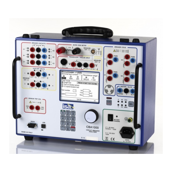
The following is the front panel; all components on the front, and the key ones inside the test set, are listed here below (see also the CBA1000 schematic at the end of the manual). 1) Supply socket and main supply fuse, rated T5A, incorporated in the supply socket. - Page 8 Doc. CEI12166 Rev. 1 Pag. 8 Of 47 12) Auxiliary inputs: dry or wet selection lights. 13) Auxiliary inputs level: ON = closed or with voltage. 14) Main contacts input sockets: three phases with two chambers each. 15) Main inputs lights: GREEN = main input CLOSED; RED = main input OPEN or pre-insertion resistor.
-
Page 9: Pushbuttons , Display , Keypad , Control Knob
Doc. CEI12166 Rev. 1 Pag. 9 Of 47 2.2 P USHBUTTONS DISPLAY KEYPAD CONTROL KNOB The test set is controlled by two push-buttons: SELECT (25), with its LED’s (26) showing the current selection , and START (27) with the light (28) , that starts the test. -
Page 10: Set
Doc. CEI12166 Rev. 1 Pag. 10 Of 47 After diagnostics, the following control window is displayed. Selections to the right are short-cuts that allow to enter the corresponding selections. They can be reached by means of the control knob (5), that incorporates a switch: this is possible selecting the item moving the knob, and then pressing the knob to confirm. -
Page 11: Menu
Doc. CEI12166 Rev. 1 Pag. 11 Of 47 The left side of the screen follows the selection. NOTE: this selection is independent from other selections, and all selected channels are saved into test results. On the same result, you can temporarily select to view on trace only, so that it can be examined at ease. -
Page 12: Trigger Options
Doc. CEI12166 Rev. 1 Pag. 12 Of 47 Main contact lines mean: . Thin line = Open contact; . Thicker line = pre-insertion resistor closed; . Thickest line = Closed contact. Auxiliary lines are: Thin = Open; Thick = Closed. Next lines are the coil currents profiles: they are four if the option is installed. - Page 13 Also, changing the current threshold changes the timing result, as the current increases slowly, because of the coil inductance. With CBA1000, coil driving is electronic: the voltage edge is steep, and there is no bounce; so, the internal trigger selection is preferable. The difference between the two selections is in the order of 1 ms.
- Page 14 - “External trigger on Slave input” selection. The test set features a Master output and a Slave input (29), that allow synchronizing up to 4 CBA1000’s (1 Master, 3 Slave). In this mode, one CBA1000 acts as the Master unit; its Master output will be connected to all other units, selected as Slave. As the Master starts the test, all other Slave units will measure the timing on Main, auxiliary and analog inputs, but don’t generate coil driving signals.
-
Page 15: Test Options
. Definition of Open commands if the of four coil drive option is available; . Definition of the test sequence. - With the “Open” selection, CBA1000 issues an Open command and records timings, according to other selections. In case of four coils, the selected Open coil phase is driven: selections are performed... - Page 16 Doc. CEI12166 Rev. 1 Pag. 16 Of 47 The selection “Cycle single phase” means that, in a series of Open commands, the first Open command will be issued on phase A; next Open command will be issued on phase B; next Open command will be issued on phase C.
-
Page 17: Recording Options
Doc. CEI12166 Rev. 1 Pag. 17 Of 47 . With the first selection, the recording is continuous, including the delay between tests. This selection is not to be used unless for short tests: the long delay reduces screen resolution and time measurement accuracy. - Page 18 Doc. CEI12166 Rev. 1 Pag. 18 Of 47 . Two recordings selection. In this mode, the measurement is performed in two steps, separated by a pause: this avoids losing the timing resolution. It is possible to program a first recording duration, then a dead time, then the second recording duration.
-
Page 19: Breaker And Auxiliary Channel Settings
Doc. CEI12166 Rev. 1 Pag. 19 Of 47 2.3.5.5 Breaker and auxiliary channel settings This selection defines the channels that will be monitored and recorded: pressing it, the following window is displayed. - In the first set of selections, related to CB contacts, it is possible to select which contacts should be monitored: “A1 only for preliminary tests;... - Page 20 Doc. CEI12166 Rev. 1 Pag. 20 Of 47 (saturated) at the selected range value, and peak current measurement will be impossible. However, in case of wrong selection no damage to measurement circuits will occur. For the Analog channel, if the box is checked the following lower part of the screen is displayed. - The “analog input”...
- Page 21 Doc. CEI12166 Rev. 1 Pag. 21 Of 47 You can select the unit of measurement, and you have to key in the stroke corresponding to the maximum transducer movement; then, the program asks you to open (or close) the CB, and displays the open and close positions, and the corresponding stroke.
-
Page 22: Micro-Ohmmeter Test
With the “Dynamic resistance test” selection it is possible to record the main contact resistance during the CB close. The CB is open prior to test start: CBA1000 issues the Close command; as the contact closes, the test current passes through the contact, and CBA1000 measures the contact resistance variations during the close movement. - Page 23 Doc. CEI12166 Rev. 1 Pag. 23 Of 47 - The “Nominal test current” selection sets the test current and also the resistance measurement range: 200 A for the 1 mOhm range, 80A for the 10 mOhm range, 25 A for the 100 mOhm range. After the current selection, the corresponding resistance range is displayed.
-
Page 24: Results
Doc. CEI12166 Rev. 1 Pag. 24 Of 47 - As above, the “Nominal test current” selection sets the test current and also the resistance measurement range: 200 A for the 1 mOhm range, 80A for the 10 mOhm range, 25 A for the 100 mOhm range. - Page 25 Doc. CEI12166 Rev. 1 Pag. 25 Of 47 It is possible to: “Save” a result, defining the file name; to “Load” a result, selecting it on the test results list; to “Delete” a result, selecting it on the test results list. If, after a test, the result is not saved, and a next test is issued, a warning message is displayed.
-
Page 26: Preferences
Doc. CEI12166 Rev. 1 Pag. 26 Of 47 2.3.5.9 Preferences This selection allows defining some ancillary selections: pressing it, the following window is displayed. - Date and time can be set with the first selection; the following window is displayed. - Page 27 Doc. CEI12166 Rev. 1 Pag. 27 Of 47 - With the “Display” selection, the following window is opened. . The contrast can be adjusted pressing on the + and – keys. . The backlight duration selection is provided for the case of battery operation, as the backlight sinks an important amount of power.
-
Page 28: Set-Up Options
Doc. CEI12166 Rev. 1 Pag. 28 Of 47 2.3.5.10 Set-up options This selection allows operating on test set-up: pressing it, the following window is displayed. - With “Save setup” it is possible to give a name to the current settings, and to save it into memory. Any setting can be saved to and recalled from the memory. - Page 29 Doc. CEI12166 Rev. 1 Pag. 29 Of 47 Also the file reading can take some time: in the meanwhile, the following message is displayed. - After “Show setup” and “Show current setup”, all selections are displayed; this helps avoiding to go through all selection windows.
-
Page 30: Tests Header
Doc. CEI12166 Rev. 1 Pag. 30 Of 47 - Results: Save. The default timing is shown below. OPEN O DURATION: 0,1 s CLOSE C DURATION: 0,5 s OC DELAY: 0,3 s PRE-TRIGGER: 0,1 s CO DELAY: 0,6 s RECORDING DURATION: 1 s If these values match with what you want to do, you can immediately start the test;... -
Page 31: Magnifying Lenses
2.4.1 Main CB contacts. The first operation is to connect CBA1000 to main CB contacts. To this purpose, are provided six sockets in all, marked A1, B1, C1, and A2, B2, C2. The first ones are used for one-chamber CB; the others are used for two-chamber CB. -
Page 32: Coil Drivers
A, B, C. 2.4.2 Coil drivers Next operation is to connect CBA1000 coil driver outputs to the CB coils. There are four groups, marked: C (Close coil); O1 (Open coil, or phase A Open coil, with four coil option);... -
Page 33: Auxiliary Cb Contacts
Pag. 33 Of 47 2.4.3 Auxiliary CB contacts. Next operation is to connect logic CBA1000 inputs to the auxiliary CB contacts, if desired. There are four inputs in all, divided in two ISOLATED groups of two inputs each. This serves for the case that a contact is with voltage, while the other one is not. -
Page 34: Connection To The Pc
2.6 C ONNECTION TO THE CBA1000 can be connected to the PC via the RS232 or the USB interface; connection cables are provided. The choice is performed on the software. If USB is used. The LED below it should turn ON as CBA1000 is connected to the PC. -
Page 35: The Hell, It Doesn't Work
Sometimes, when my ears whistle, I wonder if it is because of some of my customers being angry at us because the test set doesn’t work: according to Murphy’s law, when it was most necessary. We at ISA do our best efforts to filter the so-called infant mortality of electronic components prior to delivery of all our test sets;... -
Page 36: Physical Description
3.2 P HYSICAL DESCRIPTION CBA1000 components are accessed by removing all screws on the bottom, and also the four screws on the feet, and lifting the central part by the handles. There is a main board mounted on the front panel, and a number of components mounted on the back panel. -
Page 37: Trouble Shooting
The following table lists main faults, cause of fault and the corrective action. SYMPTOM POSSIBLE CAUSE CORRECTIVE ACTION Problems after transport Heavy shock Open CBA1000 and check for loose boards or connections. At power-on does not turn on Mains supply fuse open Check the fuse; for other problems, see 3.4.1... -
Page 38: The Test Set Is Locked Up
In this instance, the fault is likely to be located on the corresponding coil driver board, PWA11428: to the left, the board for C and O1; to the right, the board for O2 and O3. . Remove CBA1000 from the container. . Locate the faulty board, (63) OR (64). -
Page 39: A Breaker Contact Is Not Detected
. If the fault is on the board C + O1, and the second board is available, set the second board at the place of the first one: CBA1000 can be operated in three phase Open mode, until the replacement board is available. -
Page 40: The Travel Transducer Does Not Operate
. Next, remove the board (65), and replace it. 3.4.9 Problems during upgrade The firmware upgrade is performed via software. When the file is transferred into CBA1000, the following message is displayed. When the file has been transferred, the firmware upgrading is performed: this is displayed by the message: When the message disappears, the update is completed, and the test set can be operated. -
Page 41: The Fault Cannot Be Fixed
3.4.10 The fault cannot be fixed If the fault is too hard to be fixed, you have to deliver CBA1000 back to your agent. We have encountered problems caused by a poor packing of instruments that have been delivered us for calibration or repair. - Page 42 Doc. CEI12166 Rev. 1 Pag. 42 Of 47 INSTRUMENT RETURN FORM DATE ____________ AGENT _________________ COUNTRY ___________________ TYPE OF INSTRUMENT ____________________ SERIAL NO. __________________ INSTRUMENT RETURNED FOR: CALIBRATION ____ REPAIR ____ In case of repair, please specify the following. DATE OF FAULT _______________ REPORTED BY E-MAIL, PHONE ___________ COMPANY _____________________ USER’S REFERENCE ____________________ FAULT DESCRIPTION ____________________________________________________ __________________________________________________________________________...
-
Page 43: Adding Options
CBA1000 does not need to be calibrated, as metering circuits employ high stability components. It is suggested to check the unit every 3 years, by comparing CBA1000 measurements to external meters. Tests should be performed with an accurate multi-meter, that should guarantee a maximum DC measurement error of 0.1%, both for voltage and current, and some high current sample shunts,... - Page 44 Doc. CEI12166 Rev. 1 Pag. 44 Of 47 At the end of the test, if deviations are not acceptable it is possible to enter the calibration mode, and correct for deviations. 3.6.2 Calibration procedure The first window is the following. Once “Measures calibration”...
- Page 45 Doc. CEI12166 Rev. 1 Pag. 45 Of 47 The offset calibration is executed as above, short-circuiting the input. For the amplitude, you need an external, stable voltage source, such as that generated by a relay test set. Press Measure and then apply voltages, as displayed;...
- Page 46 Doc. CEI12166 Rev. 1 Pag. 46 Of 47 APPENDIX 1: SPARE PARTS LIST The following is the suggested list of spare parts for a duration of five years and for up to five test sets. The reference is made to the list of components. 1) N.
- Page 47 Doc. MIE10166 Rev. 1 Page 47 of 47 APPENDIX 2: TEST SET SCHEMATIC...
Need help?
Do you have a question about the CBA1000 and is the answer not in the manual?
Questions and answers