Table of Contents
Advertisement
Quick Links
Mark 7® 650 X & PRO Autodrive
User Manual
V 2.7
Read this manual and the Dillon Precision Manual completely. Understand all
safety and operating instructions. Failure to comply with the warnings and
instructions may result in serious injury, illness or death.
MARK 7® RELOADING USER MANUAL VERSION 2.7 COPYRIGHT 2017
1
ALL RIGHTS RESERVED
Advertisement
Table of Contents

Related Manuals for Mark 7 650


Summary of Contents for Mark 7 650
- Page 1 Read this manual and the Dillon Precision Manual completely. Understand all safety and operating instructions. Failure to comply with the warnings and instructions may result in serious injury, illness or death. MARK 7® RELOADING USER MANUAL VERSION 2.7 COPYRIGHT 2017 ALL RIGHTS RESERVED...
-
Page 2: Table Of Contents
4. Removing 650 Link Arms ....................11 5. Removing Link Arm Bottom Pin ..................12 6. Reinstalling the 650 Link Arms .................... 13 7. Connecting the Mark 7 Crank To The 650 Ram ............... 14 8. Mounting 650 ........................15 9. Installing Crank Shield ......................18 10. -
Page 3: Important Safety Instructions
– Activities using the Mark 7® 650 Autodrive are inherently dangerous and WARNING may lead to injury and even death. Actions as a result of using the Mark 7® product are solely the responsibility of the user – if you get injured through the reloading process or through the use of ammunition as a result of the reloading process it is your fault. - Page 4 Precision factory specifications and is operating within factory parameters. This includes the shell plate locating pins and other machine-specific features. Read and understand the latest Dillon Precision 650 manual for your make and model machine and ensure that you fully understand the Dillon directions.
- Page 5 Never operate the Mark 7® Autodrive at speeds higher than you have tested and are comfortable with for the type of reloading or processing that you are undertaking. Run the Mark 7® Autodrive at the slowest possible setting to create quality ammunition.
-
Page 6: Box Contents
Box Contents Please review these contents and inform us right away if you appear to be missing any of these items: Main: Mark 7® 650 AutoDrive Assembly (1 item) Middle Insert: (11 items) • Tablet • AC Power Cable •... -
Page 7: Set-Up Procedures
1. Ensure that the press/autodrive combination is on a very solid surface that does not move. The Mark 7® autodrive is designed to sit on the 4 rubber feet in the corners, but it can also be directly bolted to your work bench by removing the 4X rubber feet in the corners. -
Page 8: Removal Of Equipment From The Packing Carton
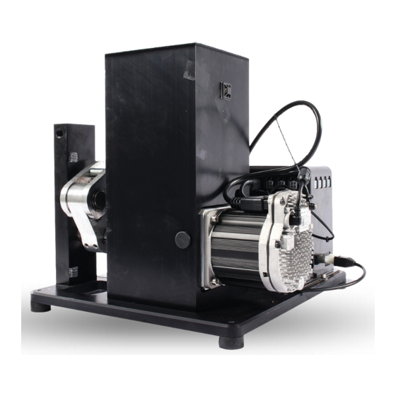
1. 650 Autodrive Component Identification Riser Mount Crank Front Support Base Plate Electronics Console Servo Motor Figure 3: 650 Base Unit Front and Rear View MARK 7® RELOADING USER MANUAL VERSION 2.7 COPYRIGHT 2017 ALL RIGHTS RESERVED... -
Page 9: Removing 650 Handle
Using a 7/8” wrench and a pin to lock the rotation of the handle remove the lock nut on the bottom of the handle as shown below. Depending on the age of the 650 press it may be required to punch out the handle out of the 650 knuckle. -
Page 10: Removing 650 Knuckle And Pin
3. Removing 650 Knuckle and pin Using a 1/8” allen key remove the set screw on the bottom of the 650 ram and slide out the knuckle pin. This pin and set screw will be re-used later in the assembly, set aside in a safe place. -
Page 11: Removing 650 Link Arms
4. Removing Link Arms From 650 - Using 2X 7/8” or (22mm) wrenches remove the nuts on the right light link arm. Slide off the right link arm, then pull out the left link arm attached with the pins as an assembly as shown in the figure below. -
Page 12: Removing Link Arm Bottom Pin
Remove the lock nut and slide the left link arm off the pin. Figure 9: Removing Lower Pin on Left Side Link Arm Figure 10: Left Link Removed MARK 7® RELOADING USER MANUAL VERSION 2.7 COPYRIGHT 2017 ALL RIGHTS RESERVED... -
Page 13: Reinstalling The 650 Link Arms
6. Reinstalling The Link Arms To The 650 Slide the upper pin in the left side link into the 650 frame. Install the right side link on the pin and tighten the lock nuts, keep the lock nuts loose so the link arms can still rotate. Final tightening will occur when the 650 is mounted to the autodrive. -
Page 14: Connecting The Mark 7 Crank To The 650 Ram
There are 2X set screws on the lower crank that lock it to drive shaft. Due to variations in the 650 press these may need to be backed out in order to line up the 650 ram to the Mark 7®... -
Page 15: Mounting 650
8. Mounting 650 Onto Mark 7® Autodrive - Place the XL 650 onto the top plate of the mount ” wrench partially tighten the ¼-20 X 1.5” hex head screws. on the autodrive. Using a 7/16 Rotate the link arms up and away from the front support. - Page 16 Insert the M14 Bolt through the Mark 7® knuckle and through the ram. We recommend moving the shell plate platform to the mid/upper position so the index ring isn’t engaged. Make sure both washers on the M14 bolt as shown in the figure below. Partially tighten with a pair of 7/8”...
- Page 17 Now that everything is connected, fully tighten the XL 650 to the riser mount, top and bottom link arms, and the M14 Screw through 650 ram. If the 4X set screws on the lower crank were loosened during the install re-tighten with medium Loctite if possible.
-
Page 18: Installing Crank Shield
Firmly press on the inside of shield to allow the adhesive to achieve a proper bond. To remove the shield gently pry at each corner with a flat head screw driver to disengage the 3M tape as shown in the right image below. MARK 7® RELOADING USER MANUAL VERSION 2.7 COPYRIGHT 2017 ALL RIGHTS RESERVED... -
Page 19: Tablet And Holder Installation
10. Tablet & holder installation The tablet holder can be mounted directly to the 650 case feeder pole or remotely next to the machine. First attach tablet holder arm to the tablet holder. The tablet holder will make a positive clicking sound when it is seated correctly. Clamp the tablet holder to the desired location. - Page 20 Figure 20: Tablet Holder orientation for 9 inch tablet (left) 10 inch (Right) Figure 21: Side view of Tablet holder 9 inch (left) 10 inch (Right) MARK 7® RELOADING USER MANUAL VERSION 2.7 COPYRIGHT 2017 ALL RIGHTS RESERVED...
- Page 21 Do not zip tie the tablet cables to Dillon case feeder or Mr. Bulletfeeder power cords. MARK 7® RELOADING USER MANUAL VERSION 2.7 COPYRIGHT 2017 ALL RIGHTS RESERVED...
-
Page 22: Console Cable Locations And Setup
11. Console cable locations and setup Micro 8-Pin Figure 23: Side of Console Inputs Before powering on the Mark 7 Units please make the following connections: Micro-USB: Tablet to Console USB data communication cable USB: Motor to Console USB data communication cable... - Page 23 – Never power on the console switch without the 6-pin Molex connector WARNING plugged in and never install this connector with the power already on since the DC voltage would damage the motor's input contacts. MARK 7® RELOADING USER MANUAL VERSION 2.7 COPYRIGHT 2017 ALL RIGHTS RESERVED...
- Page 24 The following connections below MUST be connected and secure before the unit is powered on. Refer to the previous section for optional sensor port locations Figure 25: Required System Connections MARK 7® RELOADING USER MANUAL VERSION 2.7 COPYRIGHT 2017 ALL RIGHTS RESERVED...
-
Page 25: Manually Driving Press
Use a 11/16” wrench or socket to manually drive the crank up and down to fully drive the 650. Make sure there is no interference or change in resistance during the stroke. If a jam occurs while running the machine we recommend manipulating the press manually once the jam has been cleared. -
Page 26: Emi Filter For Bulletfeeders
Mr. bulletfeeder drop tube and/or GSI feeder. Note: A small modification may be required to install the filter on the GSI feeders. Figure 27: Filter Installed on Mr. Bulletfeeder (Double Alpha) MARK 7® RELOADING USER MANUAL VERSION 2.7 COPYRIGHT 2017 ALL RIGHTS RESERVED... -
Page 27: Emi Filter For Case Feeder
WARNING – Use of the RC filter is at your risk and only for those experienced with electrical systems and is only for the systems that are experiencing interference*. MARK 7® RELOADING USER MANUAL VERSION 2.7 COPYRIGHT 2017 ALL RIGHTS RESERVED... - Page 28 Plug the Power lines into the corresponding male terminal leads on the RC filter terminals as shown below. 4. Reinstall cover plate and test for proper operation. Connection at Micro-switch Connection at On/Off Switch Figure 29: Case Feeder RC Filter MARK 7® RELOADING USER MANUAL VERSION 2.7 COPYRIGHT 2017 ALL RIGHTS RESERVED...
-
Page 29: Optical Decapping Sensor
Installing Optical Decapping Sensor WARNING – Use of the Mark 7® Decapping Sensor™ is at your risk and only for expert reloaders. This is a product that is designed to improve the safety of the reloading operation. NEVER RELY ON THE DECAPPING SENSOR. You must monitor its use –... - Page 30 In either case the recommended cleaning interval is every 500-700 rounds that are decapped. Using a duster can or compressed air, spray into spent primer hole in the 650 platform and into the front hole on the decap sensor shown below. It may be necessary to remove the sensor.
- Page 31 SENSOR™ AS OFTEN AS PRACTICAL – IT IS UP-TO YOU TO ENSURE THE SENSOR IS CLEAN. If you don’t have mounting holes for the decapping sensor on the bottom of you 650 platform you will need to upgrade to the new style design Dillon Part # 22060. You will also need the new style primer punch for both small and large primer Dillon Part # 21380 &...
-
Page 32: (Optional)
A 45 Caliber case or equivalent weight can be put at the top of the primer follower stick if needed to ensure accurate depression of the hardware primer sensor. MARK 7® RELOADING USER MANUAL VERSION 2.7 COPYRIGHT 2017 ALL RIGHTS RESERVED... -
Page 33: (Optional)
Figure 35: Package Contents 2. Check the software and firmware version installed on your machine and make sure it’s at least the version listed below (or newer) before installing 650 BulletSense®. The latest updates are available on the software updates page. - Page 34 2. If Locate and remove the offloading bracket bolts (X2) with a 7-16” socket and set aside (see Figure 2). Figure 36: Removing offload bracket MARK 7® RELOADING USER MANUAL VERSION 2.7 COPYRIGHT 2017 ALL RIGHTS RESERVED...
- Page 35 3/16” Allen wrench and with a 7/16” socket affixed on the opposite side of the press (see Figures 3 and 4). Figure 37: Case Feeder Mounting Bolt Locations MARK 7® RELOADING USER MANUAL VERSION 2.7 COPYRIGHT 2017 ALL RIGHTS RESERVED...
- Page 36 4. Install the 650 BulletSense Bracket Assembly as shown in the figure below (Figure 4). Use the longer ¼-20” bolts provided. Figure 38: Installing BulletSense on XL 650. MARK 7® RELOADING USER MANUAL VERSION 2.7 COPYRIGHT 2017 ALL RIGHTS RESERVED...
- Page 37 (it just covers the bottom of the mirror). This isn't an issue though because the laser head is mounted higher due to the taller cases and longer projectiles. Adjusting BulletSense® Laser for Station 4 and Station 5: MARK 7® RELOADING USER MANUAL VERSION 2.7 COPYRIGHT 2017 ALL RIGHTS RESERVED...
- Page 38 Station 4: BulletFeeder dropper in Station 3 with standard crimp and seat dies. Station 5: BulletFeeder dropper in Station 4. (using PowderSense® Powder check) 2. Once you decide which station, align the 650 BulletSense assembly with the mirror holder by loosening the sensor head mount (middle arm) brass thumb screw and rotating the sensor head to meet the mirror (see Figure 6).
- Page 39 5. Next the sensor vertical height must set for the given caliber and projectile being used. This must be performed when the platform assembly is in the home position. Before MARK 7® RELOADING USER MANUAL VERSION 2.7 COPYRIGHT 2017 ALL RIGHTS RESERVED...
- Page 40 (Figures 8 and 9). Once the height has been set, remove the bullet and make sure the laser is still aimed at the sensor hole. Figure 42: Setting Vertical height of laser MARK 7® RELOADING USER MANUAL VERSION 2.7 COPYRIGHT 2017 ALL RIGHTS RESERVED...
- Page 41 11. The sensor head assembly is designed to be rotated out of the way if you need to access the shell plate or perform press maintenance. Use the plastic knob on top of the rod to lift and rotate the sensor away from the machine. MARK 7® RELOADING USER MANUAL VERSION 2.7 COPYRIGHT 2017 ALL RIGHTS RESERVED...
- Page 42 4. Perform a system calibration then select the sensors tab and make sure BulletSense® is enabled. (See Figure 11). 5. Press RUN or Single Cycle. With a clear shell plate the following notification should appear “Bullet Not Properly Positioned.” (see Figure 12). MARK 7® RELOADING USER MANUAL VERSION 2.7 COPYRIGHT 2017 ALL RIGHTS RESERVED...
- Page 43 Figure 45: Enabling BulletSense® on Sensor tab Figure 46: Bullet Not Properly Positioned Notification MARK 7® RELOADING USER MANUAL VERSION 2.7 COPYRIGHT 2017 ALL RIGHTS RESERVED...
-
Page 44: Operating Instructions
Operating Instructions Power on the 650 autodrive by turning on the on/off switch on the power console and pressing and holding the tablet power button until the android screen appears. The tablet will automatically launch the Mark 7 Home screen as shown below. -
Page 45: Waiver Screen & Software/Firmware Version
The waiver screen will appear if all system cables are connected properly. The operator must accept the terms and conditions and waiver on the Mark 7® Reloading website in order to run the machine. If the operator does not accept these terms they must touch DENY which will immediately close the application. -
Page 46: Control Screen
CALIBRATE - The function is the first operation that must be run before fully running the Mark 7® Autodrive. CALIBRATE signals the Mark 7® Autodrive to find the top and bottom of the machines stroke. Once calibration is completed all Mark 7® Autodrive features can be used. -
Page 47: Monitors Screen
RUN - The RUN function signals the Mark 7® Autodrive to begin operation at the settings requested. ROUNDS PER HOUR – The 650 X has 2 speeds 900 and 1200. The 650 PRO has 4 speeds 900, 1200, 1500 and 1800. -
Page 48: Sensors Screen
SET PRIMER - The operator has the ability to set the number of primers used before the Mark 7® Autodrive ends its current run. SET BRASS - The operator has the ability to set the number of brass used before the Mark 7® Autodrive ends its current run. -
Page 49: Setup Screen
TOP DWELL - The TOP DWELL function allows the operator the ability to increase the time in which the press remains at the Top of the stroke. The higher the value in the TOP DWELL field the longer the press will pause. MARK 7® RELOADING USER MANUAL VERSION 2.7 COPYRIGHT 2017 ALL RIGHTS RESERVED... - Page 50 We recommend you to gauge your brass when using this setting and be-careful not to back it off too much. There are have been different versions of the 650 primer punch over the years, if you have an older version you will need to increase the primer depth setting to achieve a proper primer depth.
-
Page 51: Software And Firmware Update
*May only be included in some update packages 2. Inset the Micro SD card into the SD card adapter that was provided with the Mark 7® Autodrive and load the downloaded .hex and .apk file(s) onto the SD card via a SD card reader. - Page 52 UPDATE, then press UPLOAD and press CLOSE when complete. Select the Reloader application and confirm that software version and firmware at the waiver screen is the same as what was just installed. Figure 55: Firmware installation Process MARK 7® RELOADING USER MANUAL VERSION 2.7 COPYRIGHT 2017 ALL RIGHTS RESERVED...
- Page 53 Troubleshooting: software and firmware updates Selecting Firmware update flashes a black screen then goes back to the main screen. Make sure the Mark 7® console is powered on and the USB cable is connected between the tablet and console. Upgrading the firmware takes longer than 5 seconds or freezes.
-
Page 54: General Maintenance And Storage
3. Turn off the power to the console of the autodrive 4. Turn off the power to the case feeder and the bullet feeder 5. Turn off the power to the tablet MARK 7® RELOADING USER MANUAL VERSION 2.7 COPYRIGHT 2017 ALL RIGHTS RESERVED... -
Page 55: Reloading Manual
Reloading Manual Ensuring proper system operation Before using any Mark 7® equipment you must ensure that your Dillon 650 works perfectly in manual mode. This includes proper settings for the type of ammunitions you are reloading at each of the die stations. You must load your perfect ammo in manual mode before installing the Mark 7®... -
Page 56: Digital Clutch Setting
The digital clutch should be set at the lowest possible setting to produce quality ammunition. The Mark 7® Autordrive is shipped with the digital clutch set at 0; this will need to be increased for operation. Settings “1”, “2” or “3” should accommodate the vast majority of pistol calibers. -
Page 57: Settings
Mark 7® Autodrive before attempting to clear a jam. If you experience a jam or any type of activity that requires you to turn off the Mark 7® Autodrive at the console, you may decide or be required to calibrate the Mark 7®... -
Page 58: Communications Errors
• Route the Dillon power cord and Mr.Bulletfeeder power cables away from tablet USB and power cords. Do not zip tie the Dillon Power cord to the 650 case feeder pole. • Power the Mr.Bulletfeeder & Dillon case feeder on their own surge protector if possible.
Need help?
Do you have a question about the 650 and is the answer not in the manual?
Questions and answers