Advertisement
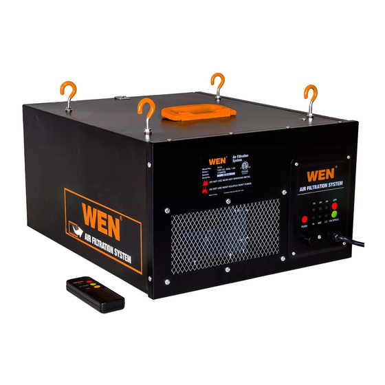
This is a guide to replacing the PCB on your WEN 3410 3-Speed Remote-Controlled Air Filtration
System. This guide is best used in conjunction with the 3410 manual, included as a physical copy with
your unit and available on the WEN website page for the 3410 (link here), under the Downloads tab.
If at any point you need assistance, have questions, or want to order parts, call WEN customer service
at 1-800-232-1195, M-F, 8-5 Central Time, or email techsupport@wenproducts.com.
Table of contents
•
Disassembling the unit......................................................................................1
•
Choosing the correct PCB..................................................................................1
•
Replacing the PCB...........................................................................................2
Disassembling the unit
You will need:
•
A Phillips-head screwdriver
•
Cutting pliers (diagonal-cutting or flush-cutting)
•
Needle-nose pliers, adjustable pliers, or a ratcheting socket wrench and sockets
You may want:
•
A heat gun. We recommend the WEN 2020 1500W Dual-Temperature Heat Gun Kit, available
for purchase online.
Choosing the correct PCB
•
Refer to the Parts List and exploded view in the back of your manual for the correct part
number for your PCB and remote control. However, if the manual is not available, or you are
unsure, refer to Table 1 below. Refer to the remote ORIGINALLY included with your unit.
•
NOTE: this guide is written with newer 3410 units in mind. Steps may be similar for older
units, but may not necessarily be identical. Call 1-800-232-1195 with questions.
IF YOUR REMOTE LOOKS LIKE THIS...
Remote with bumps on the bottom.
White remote with black top
CHOOSE THESE PART NUMBERS
•
Remote part number: 90243-029
•
PCB part number: 90243-046
•
Control system: infrared
•
Remote part number: 3410T-AS03
•
PCB part number: 3410T-045
•
Control system: radio frequency
Advertisement
Table of Contents

Related Manuals for Wen 3410


Summary of Contents for Wen 3410
- Page 1 This is a guide to replacing the PCB on your WEN 3410 3-Speed Remote-Controlled Air Filtration System. This guide is best used in conjunction with the 3410 manual, included as a physical copy with your unit and available on the WEN website page for the 3410 (link here), under the Downloads tab.
- Page 2 Control system: radio frequency NOTE: The remote and PCB can be replaced with parts 3410-029RF-01 (remote) and 3410-046RF-01 (PCB) in a set. Remote 3410-029RF will not work with PCB 3410-046RF-01, and remote 3410-029RF- Black remote with RF logo in the bottom left 01 will not work with PCB 3410-046RF.
- Page 3 3. Using the Phillips head screwdriver, remove the ten screws found around the perimeter of the front panel, as indicated by the red arrows in Figure 2 below. Figure 2: Remove these ten screws. 4. Set the screws aside. Look on the top of the unit near the handle. Notice the grounding bolt shown in Figures 3 and 4 below.
- Page 4 Figure 4: Inside of grounding bolt. 5. Using the Phillips-head screwdriver, as well as something to hold the nut shown in Figure 4 above (pliers, socket, adjustable wrench, etc.), loosen and remove the nut, then remove the grounding wire and bolt. Do not drop the washers. If you do drop them, retrieve them from the grating, or turn the unit over.
- Page 5 9. Flip the unit over so that the front control panel is accessible. You may want to prepare a heat gun (without any nozzles or other attachments) for use on this step. We recommend the WEN 2020 1500W Dual-Temperature Heat Gun Kit, available for purchase online. On the lowest heat setting, evenly warm the adhesive sticker on the front panel, outlined in yellow in Figure 6 below.
- Page 6 10. Remove the PCB and housing from the rear of the control panel. Refer to Figures 8 and 9 below. Using the cutting pliers, carefully cut only the zip tie that secures the radio antenna to the housing. Figure 8: Cut the zip tie. Figure 9: Zip tie has been cut.
- Page 7 Figure 11: Assemble grounding bolt as shown here. QUESTIONS? CONCERNS? CALL OUR CUSTOMER SERVICE HOTLINE AT 1-800-232-1195, M – F, 8 – 5 CENTRAL TIME, OR EMAIL TECHSUPPORT@WENPRODUCTS.COM.
Need help?
Do you have a question about the 3410 and is the answer not in the manual?
Questions and answers