Advertisement
Quick Links
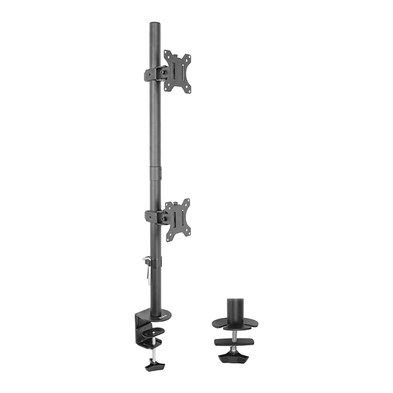
Dual Monitor Desk Mount
Instruction Manual
SKU: STAND-V002T
Scan the QR code with your mobile device or follow the link
for helpful videos and specifications related to this product.
https://vivo-us.com/products/stand-v002t
GET IN TOUCH | Monday-Friday from 7:00am-7:00pm CST
help@vivo-us.com
www.vivo-us.com
Chat live with an agent!
309-278-5303
Advertisement

Related Manuals for Vivo STAND-V002T


Summary of Contents for Vivo STAND-V002T
- Page 1 Dual Monitor Desk Mount Instruction Manual SKU: STAND-V002T Scan the QR code with your mobile device or follow the link for helpful videos and specifications related to this product. https://vivo-us.com/products/stand-v002t GET IN TOUCH | Monday-Friday from 7:00am-7:00pm CST help@vivo-us.com www.vivo-us.com...
-
Page 2: Package Contents
WARNING! If you do not understand these directions, or if you have any doubts about the safety of the installation, please call a qualified technician. Check carefully to make sure there are no missing or defective parts. Improper installation may cause damage or serious injury. Do not use this product for any purpose that is not explicitly specified in this manual. -
Page 3: Tools Needed
TOOLS NEEDED DO NOT EXCEED WEIGHT CAPACITY. 22 lbs Failure to do so may result in serious injury. (10 kg) PER ARM Phillips Screwdriver ASSEMBLY STEPS STEP 1 Attach cap (F) to top of pole (E). STEP 2 OPTION A: Clamp Installation Stick rubber pads (J) to the underside of clamp (C). - Page 4 STEP 2 (Continued) OPTION B: Grommet Base Installation For grommet hole mounting, remove screw in top of bolt on clamp (C). Stick rubber pads (J) to bottom of grommet base (I). Attach metal plate (L) to bolt and run through grommet hole into grommet base (I) and thread into pole (D) as shown in diagram.
- Page 5 STEP 4 Attach pole (E) to pole (D) using pole connector (G). Tighten grub screws in pole connector using 3mm allen key (N). Slide cable management clip (H) and bracket (B) onto pole (E) and tighten using 6mm allen key (P). STEP 5 OPTION A: Flat Back Monitor Attach VESA plates (A) to back of monitors using bolts (M-A, M-C) and washers (M-E).
- Page 6 STEP 5 (Continued) OPTION B: Curved Back Monitor Attach VESA plates (A) to back of monitors using bolts (M-B or M-D). If bolts are too long, spacer (M-F) may be required. M- E M- B M- D M- F STEP 6 Slide VESA plates (A) into brackets (B) and secure using thumb screws (M) as shown in diagram.
- Page 7 STEP 8 Run cables through cable management clips (H). STEP 9 Store allen keys (N,O,P) in cable management clips (H) for future adjustments. Adjust as Desired 180° +45° -45° 360° 180° +45° -45° 360°...
- Page 8 - 92% within < 3hr www.vivo-us.com : < 15 M AVG. RESOLUTION TIME (within office hrs) Chat live with an agent! : 5M 4S 309-278-5303 AVG. RESOLUTION TIME (within office hrs) FOR MORE VIVO PRODUCTS, CHECK OUT OUR WEBSITE AT: www.vivo-us.com...
Need help?
Do you have a question about the STAND-V002T and is the answer not in the manual?
Questions and answers