YASKAWA V1000 Product Transition Manual
Industrial ac microdrive
Hide thumbs
Also See for V1000:
- Technical manual (480 pages) ,
- Quick start manual (231 pages) ,
- Installation manual (57 pages)
Table of Contents
Advertisement
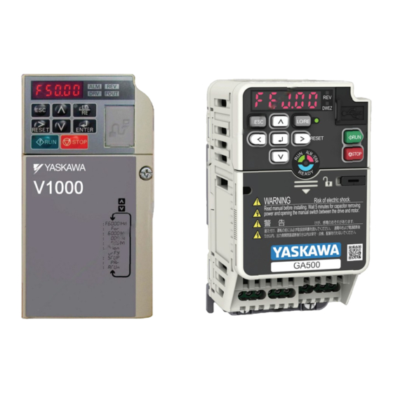
V1000 to GA500
Industrial AC Microdrive
Product Transition Guide
240 V Single-Phase Input : 1/8 to 5 HP
240 V Three-Phase Input : 1/8 to 25 HP
480 V Three-Phase Input : 1/2 to 25 HP
This guide lists only comparable models. Refer to the GA500 Selection Guide
No. SL.GA500.01 for a list of all available models.
Catalog Code: GA50U
240 V Single-Phase Input : 1/6 to 5 HP
240 V Three-Phase Input : 1/6 to 30 HP
480 V Three-Phase Input : 1/2 to 40 HP
Advertisement
Table of Contents

Related Manuals for YASKAWA V1000


Summary of Contents for YASKAWA V1000
- Page 1 V1000 to GA500 Industrial AC Microdrive Product Transition Guide Catalog Code: GA50U 240 V Single-Phase Input : 1/8 to 5 HP 240 V Single-Phase Input : 1/6 to 5 HP 240 V Three-Phase Input : 1/8 to 25 HP 240 V Three-Phase Input : 1/6 to 30 HP...
- Page 3 AC Drive Transition Guide V1000 to GA500 This document is intended to help OEM's, Integrators, and End Users select and replace Yaskawa V1000 series AC drives with Yaskawa GA500 AC drives. Replacement should be conducted by qualified personnel familiar with AC drive installation. Follow local electrical codes during replacement and installation.
- Page 4 240 V, Single-phase EMC Noise Filter 480 V, Three-phase No built-in filter 480 V, Three-phase Built-in EMC Filter Rated Output Current Note: Refer to rated output current specification YASKAWA America, Inc. PL.GA500.01 YASKAWA AC Drive - V1000 to GA500 Transition Guide...
- Page 5 2030 25.0 30.0 2A0040 33.0 40.0 2042 33.0 42.0 2A0056 47.0 56.0 2056 47.0 56.0 2A0069 60.0 69.0 2070 60.0 70.0 2082 75.0 82.0 YASKAWA America, Inc. PL.GA500.01 YASKAWA AC Drive - V1000 to GA500 Transition Guide...
- Page 6 4A0023 18.0 23.0 4023 18.0 23.4 4A0031 24.0 31.0 4031 24.0 31.0 4A0038 31.0 38.0 4038 31.0 38.0 4044 39.0 44.0 4060 45.0 60.0 YASKAWA America, Inc. PL.GA500.01 YASKAWA AC Drive - V1000 to GA500 Transition Guide...
- Page 7 Dimension Comparison and Mounting Kits The standard model V1000 enclosure is wall-mount UL Type 1. GA500 dimensions for the optional UL Type 1 kit assembled to the GA500 are also shown. Use these tables to understand physical dimensions when required for replacing the V1000 with a new GA500 drive.
- Page 8 11.42 x 7.09 x 6.42 11.81 x 7.09 x 5.63 13.39 x 7.09 x 5.63 4044 ZBAA-GA50V8-1 13.78 x 7.48 x 8.03 15.87 x 7.48 x 8.03 4060 YASKAWA America, Inc. PL.GA500.01 YASKAWA AC Drive - V1000 to GA500 Transition Guide...
- Page 9 4 Branch Circuit Protection Branch Circuit Protection Use this section to understand if the existing V1000 branch circuit protection is suitable for the replacement GA500 drive. V1000 Branch Circuit Protection Table 7 V1000 Branch Circuit Protection Fuse Type: Class T, Non-Time Delay...
- Page 10 GA500 Branch Circuit Protection Use branch circuit protection to protect against short circuits and to maintain compliance with UL61800-5-1. Yaskawa recommends connecting semiconductor protection fuses on the input side for branch circuit protection. • 240 V model fuse selection: Use the fuses specified in this document or in the drive product instructions to prepare the drive for use on a circuit that supplies not more than 31,000 Amps RMS and not more than 240 Vac when there is a short circuit in the power supply.
- Page 11 Fuse Type: Semiconductor Fuse, Fast Acting GA500 Catalog Code Fuse Type: Class J, T, and CC Time-delay (Manufacturer: EATON/Bussmann) GA50U_ Rated Current (A) Model 4031 FWH-125B 4038 FWH-175B 4044 FWH-200B 4060 FWH-200B YASKAWA America, Inc. PL.GA500.01 YASKAWA AC Drive - V1000 to GA500 Transition Guide...
- Page 12 5 Main Circuit and Motor Wiring Main Circuit and Motor Wiring Use this section to convert the V1000 main circuit wiring for installation to the GA500. Key wiring differences between the V1000 and GA500 are: • V1000 uses crimp terminals/ring lugs and GA500 accepts bare wire (except for ground terminal).
- Page 13 Wire Termination Differences V1000 to GA500 If crimp terminal ends/ring lugs are present on the V1000, they must be removed and the wire stripped to bare wire for installation to the GA500. Refer to the GA500 Installation & Primary Operation Manual No. TOEPC71061752, for more information on wire termination.
- Page 14 , 2042, 4018, 4023 Models: GA50U2056 , 4031, 4038 Models: GA50U2070 , 2082 Models: GA50U4044 , 4060 Figure 3 GA500 Main Circuit and Motor Circuit Terminal Layout by Model YASKAWA America, Inc. PL.GA500.01 YASKAWA AC Drive - V1000 to GA500 Transition Guide...
- Page 15 5 Main Circuit and Motor Wiring Main Circuit and Motor Wire Gauge and Tightening Torque Table 9 lists wire gauge for the drive main circuit terminals. Verify the existing V1000 wire size is within the Wire Range and Recommended Gauge for the GA500. ...
- Page 16 10 to 6 2042 -, +1, +2 10 to 2 B1, B2 – 14 to 10 B1, B2 14 to 6 Ground 10 to 6 Ground 10 to 6 YASKAWA America, Inc. PL.GA500.01 YASKAWA AC Drive - V1000 to GA500 Transition Guide...
- Page 17 10 to 6 4023 -, +1, +2 12 to 6 B1, B2 – 14 to 10 B1, B2 14 to 10 Ground 10 to 6 Ground 10 to 6 YASKAWA America, Inc. PL.GA500.01 YASKAWA AC Drive - V1000 to GA500 Transition Guide...
- Page 18 R/L1, S/L2, T/L3 8 to 2 U/T1, V/T2, W/T3 10 to 2 – 4060 -, +1, +2 6 to 2 B1, B2 12 to 6 Ground 10 to 6 YASKAWA America, Inc. PL.GA500.01 YASKAWA AC Drive - V1000 to GA500 Transition Guide...
- Page 19 6 Control Circuit Wiring Control Circuit Wiring Use this section to understand differences between the V1000 and GA500 control circuit wiring to transfer control circuit wiring to the GA500. Refer to the GA500 Installation & Primary Operation Manual or Technical Reference for more details and precautions when wiring the GA500 control circuit terminals.
- Page 20 Safe Disable <7> Input Jumper MEMOBUS/ Modbus comm. RS-485/422 Cable shield ground shielded line twisted-pair shielded line control terminal main circuit terminal Figure 6 V1000 Connection Diagram YASKAWA America, Inc. PL.GA500.01 YASKAWA AC Drive - V1000 to GA500 Transition Guide...
- Page 21 6 Control Circuit Wiring Figure 7 GA500 AC Microdrive Figure 7 GA500 Connection Diagram YASKAWA America, Inc. PL.GA500.01 YASKAWA AC Drive - V1000 to GA500 Transition Guide...
- Page 22 NOTICE: Do not close the circuit Safe Disable function common +24 Vdc (Maximum 10 mA) between terminals HC and SN. A closed circuit between these terminals will cause damage to the drive. YASKAWA America, Inc. PL.GA500.01 YASKAWA AC Drive - V1000 to GA500 Transition Guide...
- Page 23 Multi-function photocoupler output 2 2 to 50 mA 2 to 50 mA (Speed agree 1) Photocoupler common Pulse train output 32 kHz (Maximum) 32 kHz (Maximum) (Output frequency) YASKAWA America, Inc. PL.GA500.01 YASKAWA AC Drive - V1000 to GA500 Transition Guide...
- Page 24 RS-485/422 MEMOBUS/ Modbus RS-485 MEMOBUS/ Modbus communication protocol 115.2 kbps communication protocol 115.2 kbps Communications input (-) (Maximum) (Maximum) Communications output (+) Communications output (-) Shield ground YASKAWA America, Inc. PL.GA500.01 YASKAWA AC Drive - V1000 to GA500 Transition Guide...
- Page 25 0.5 - 0.6 0.75 (24 -16) 0.25 - 1.0 MA, MB, MC (4.4 - 5.3) (18) Solid wire: (20) (24 - 17) 0.25 - 1.5 (24 - 16) YASKAWA America, Inc. PL.GA500.01 YASKAWA AC Drive - V1000 to GA500 Transition Guide...
- Page 26 R-, R+, S-S+ setting SINK Sinking Mode (0 V common): default setting Sinking/sourcing mode switch for digital input terminals S1~S7 SOURCE Sourcing Mode (+24 V common) YASKAWA America, Inc. PL.GA500.01 YASKAWA AC Drive - V1000 to GA500 Transition Guide...
- Page 27 Sets the input method for terminal A2 (voltage or current). Enables and disables the MEMOBUS/Modbus communications DIP SW S2 termination resistor. Jumper S5 V (voltage output) Sets the output method for terminal AM (voltage or current). YASKAWA America, Inc. PL.GA500.01 YASKAWA AC Drive - V1000 to GA500 Transition Guide...
- Page 28 7 Transfer of Parameter Settings Transfer of Parameter Settings Use this section to transfer V1000 parameter settings to the GA500. There are several methods to transfer parameters. • Transfer Parameters via DriveWizard Industrial PC Software on page 28 (recommended) Yaskawa recommends the use of DriveWizard Industrial to transfer parameters.
- Page 29 7 Transfer of Parameter Settings YASKAWA America, Inc. PL.GA500.01 YASKAWA AC Drive - V1000 to GA500 Transition Guide...
- Page 30 About DriveWizard Mobile for Android and iOS DriveWizard Mobile is DriveWizard for mobile devices. It does not have a feature to transfer parameters between V1000 and GA500, but it is very useful for commissioning GA500 drives with your smartphone or tablet.
- Page 31 Procedure - Manual Transfer of V1000 Parameters to the GA500 using the Keypad An easy way to view which V1000 parameters differ from factory settings is to use the V1000 urFy or verify menu. If no parameters differ from factory settings then the V1000 will display “None”. Record the parameters and their settings in a log so they can be manually entered into the replacement GA500 drive.
- Page 32 Some of the setting ranges and default settings for certain parameters differ between V1000 and GA500. Table 15 only lists setting range or default setting differences between similar V1000 and GA500 parameters. Table 15 is not a comprehensive comparison of all parameter differences between V1000 and GA500. For example, GA500 parameters that have no equal in the V1000 are omitted.
- Page 33 DEC Hz 0.0~590.0 0.0~400.0 Depend Stop (all 0.0) hold and the time to maintain that frequency at start. Parameters b6-03 and b6-04 do the same at top. YASKAWA America, Inc. PL.GA500.01 YASKAWA AC Drive - V1000 to GA500 Transition Guide...
- Page 34 This value seldom needs to be changed. Number of Motor Sets the number of motor poles. This value is 0x0311 E2-04 2~120 2~48 Poles automatically set during Auto-Tuning. YASKAWA America, Inc. PL.GA500.01 YASKAWA AC Drive - V1000 to GA500 Transition Guide...
- Page 35 Sets the time required to detect a 0x0435 H5-09 CE Detection Time communications error. Adjustment may be need DEC sec 0.0~25.0 0.0~10.0 when networking several drives. YASKAWA America, Inc. PL.GA500.01 YASKAWA AC Drive - V1000 to GA500 Transition Guide...
- Page 36 Sets the ratio between the connected machinery 0x046F L3-25 Load Inertia Ratio 0.1~1000.0 0.0~1000.0 1.0 and the motor. Pre-Stall Acceleration 0x0456 L3-27 Pre-Stall Acceleration Time DEC ms 0~5000 20~150 Time YASKAWA America, Inc. PL.GA500.01 YASKAWA AC Drive - V1000 to GA500 Transition Guide...
- Page 37 There is a need to set C3-28=2. Superimposed Sets the frequency in Hz for the superimposed 0x0563 N8-36 DEC Hz 200~5000 200~1000 Harmonic Frequency signal used for superimposed harmonics. YASKAWA America, Inc. PL.GA500.01 YASKAWA AC Drive - V1000 to GA500 Transition Guide...
- Page 38 0.03~ 0x0702 T1-02 Motor Rated Power DEC kW 0.40 0.40 power in kW can be calculated using the 650.00 650.00 following formula: kW = HP x 0.746 YASKAWA America, Inc. PL.GA500.01 YASKAWA AC Drive - V1000 to GA500 Transition Guide...
- Page 39 Stationary Test Mode Auto-Tuning is complete. 0xBdB T1-12 Selection Note: This selection is possible when T1-10 [Motor Rated Slip Frequency] = 0 Hz. 0: No 1: Yes YASKAWA America, Inc. PL.GA500.01 YASKAWA AC Drive - V1000 to GA500 Transition Guide...
- Page 40 To understand the effect of changing the Carrier Frequency on your new replacement drive, refer to the GA500 Technical Reference SIEPC71061752, Section 10.7 Drive Derating, Carrier Frequency Settings and Rated Current Values. Download here: http://www.yaskawa.com/SIEPC71061752 YASKAWA America, Inc. PL.GA500.01 YASKAWA AC Drive - V1000 to GA500 Transition Guide...
- Page 41 9 Watt Loss Comparison Watt Loss Comparison Use this section to understand the watt loss difference between the V1000 and GA500. This is useful to ensure proper cooling for GA500 drives that replace V1000 drives inside of enclosures. Understanding the “Difference” columns in Table 16 through Table 21.
- Page 42 149.2 -29.3 2A0056 347.6 117.6 465.2 2056 85.0 318.0 403.0 -262.6 200.4 -62.2 2A0069 437.7 151.4 589.1 2070 119.0 473.0 592.0 -318.7 321.6 2082 148.0 525.0 673.0 YASKAWA America, Inc. PL.GA500.01 YASKAWA AC Drive - V1000 to GA500 Transition Guide...
- Page 43 372.8 4031 79.0 255.0 334.0 -187.9 149.1 -38.8 4A0038 319.1 126.6 445.7 4038 95.0 338.0 433.0 -224.1 211.4 -12.7 4044 127.0 442.0 569.0 4060 135.0 446.0 581.0 YASKAWA America, Inc. PL.GA500.01 YASKAWA AC Drive - V1000 to GA500 Transition Guide...
- Page 44 10 Network Communication and Control I/O Options Network Communication and Control I/O Options V1000 network communication and I/O options are generally compatible with GA500. Firmware inside these options may require an update to support GA500. Refer to the “Applicable Products” section of the specific Option Installation Manual on www.yaskawa.com to get the compatible firmware version required in the option card.
- Page 45 11 Other Option Compatibility Other Option Compatibility Use this section to understand the compatibility of other V1000 options for the GA500. Navigate to the “Options” section of the GA500 product page for more information on GA500 compatible options. URL: https://www.yaskawa.com/products/drives/industrial-ac-drives/microdrives/ga500-drive •...
- Page 46 11 Other Option Compatibility YASKAWA America, Inc. PL.GA500.01 YASKAWA AC Drive - V1000 to GA500 Transition Guide...
- Page 48 YASKAWA AMERICA, INC. 2121, Norman Drive South, Waukegan, IL 60085, U.S.A. +1-800-YASKAWA (927-5292) http://www.yaskawa.com Specifications are subject to change without notice for ongoing product modifications and improvements. © 2020 YASKAWA America, Inc. PL.GA500.01 Revision: A <0>-0 February 2020 Published in U.S.A.
Need help?
Do you have a question about the V1000 and is the answer not in the manual?
Questions and answers