Advertisement
Quick Links
Advertisement

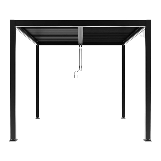
Summary of Contents for Dancover Gazebo San Pablo 3x3m
- Page 1 Manual Gazebo San Pablo 3x3m, 3x4m and 4x4m 21-09-2020...
-
Page 2: Manual Instruction
Manual Instruction Pergola 3x3m, 3x4m, 4x4m... -
Page 3: Spare Parts List
Spare parts list Label No. Part description Drawing Column Beam (Left) Beam(Right) Front and rear beams Middle beam 3x3=44 3x4=60 Flap 4x4=60 Column bottom plate Column cover plate Connectors for middle beams Hinge ring Hand crank... - Page 4 Part description Label No. Drawing Countersunk 40+2 M6x16 head screw Pan head 20+2 M6x16 screw D6x12 Flat washer M4x25 Screw+nut Woodworking screw+ M8x80 plastic expansion pipe +Flat washer 10x50 Glass glue 3x3=88 Plastic jam 3x4=120 4x4=120...
- Page 5 1. Install the bottom plate F on the column A, and tighten the screw K1; complete 4 sets in sequence. QTY: 16PCS QTY:4PCS...
- Page 6 2. Match the connector H with one side of middle beam D, then tighten the screw K1; then complete the other side. QTY:8PCS QTY:2PCS...
- Page 7 3. Put two hinge rings I into the gearbox drive shaft on the beam D, fix the screw + nut K4 QTY:2PCS QTY:2 SETS M4x25...
- Page 8 4. Place the column and beam as shown in the figure, and note that the drain port of the column faces the same side; Drain port Drain port Drain port Drain port...
- Page 9 5. The two ends of one front and rear beam C are respectively placed on the corner connectors on the column, and the screws K1 are tightened; QTY:4PCS...
- Page 10 respectively placed on the corner 6. The left and right beams B1/B2 are the screws K1 are tightened; connectors on the column, and QTY:8PCS...
- Page 11 7. Insert ends of the other front and rear beams C into the corner connectors on the column, and tighten the screws K1; QTY:4PCS...
- Page 12 8.The 4 column cover plates G are respectively mounted on the corner connectors of the column and the beam, and the screws K2 are tightened in turn; QTY:12PCS QTY:4PCS...
- Page 13 9. Adjust the position of the four columns so that they are perpendicular to the ground. Meanwhile, the width of the top of each two columns should be measured in accordance with the width of the bottom of each two columns. Then use a market pen to mark 16 holes on the ground, which should be corresponding to the holes in the botton palte.
- Page 14 10. Remove the product from the mark and drill holes of 10x80 at 16 mark positions on the ground with a percussion drill. Drilling depth 10x80 Drilling quantity 16pcs Use Tool: Percussion Bit Use Tools: Percussion Drill (Self-provided by Installation workers) (Self-provided by Installation workers)
- Page 15 11. Place the plastic expansion pipe in the bottom hole of the column; then move the product back to the hole drilled, align holes of the column bottom plates with the hole drilled on the ground; then set L1 into the woodworking screw L, and fix it with the ground separately.
- Page 16 12. Coat the glass glue M evenly on the drain of column and joints of beams.
- Page 17 13. Place the middle beam D on the front and rear beams C.
- Page 18 14. Insert 6pcs flap (E) first (4pieces at gear box side and 2pcs at other side) on the end of the brackets on both sides of the beams (B1-D and B2-D), and press down on the slat as shown in the sketch below to secure it.
- Page 19 15.First, fix screw K2 with gasket K3 align with hole below the beam D, then same to beam C. Insert the other flap in turn.
- Page 20 16. Adjust according to below steps if the pergola can`t close completly A: flap B: flapsupport Hole "A" and hole "B" must be concentric Adjust solution if hole"A" and hole "B" are not concentric straight screwdriver Adjusting the B flap support with Hole "A“...
- Page 21 17. Insert plastic jam N into two sides of each flap. 1. The following image shows how to insert plastic jam into foremost flap. 2.Turn on the flap to half position, insert the plastic jam N into hole of two ends of each flap in turn.
- Page 22 18. Put the hand crank J on, turn to open/close the flap; installation completed.


Need help?
Do you have a question about the Gazebo San Pablo 3x3m and is the answer not in the manual?
Questions and answers