
Subscribe to Our Youtube Channel
Related Manuals for Lumiax Magic Series


Summary of Contents for Lumiax Magic Series
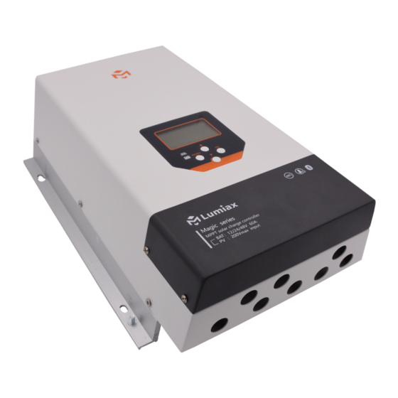
- Page 1 1.03.02.10038-1 Lumiax Magic your solar life Magic series MPPT Solar Controller 12/24/48V,750/1500/3000W User Manual User Manual_Magic series_KC CE, Rohs, ISO9001:2015 Subject to change without notice!
-
Page 2: Table Of Contents
Contents Safety instructions and waiver of liability ................Safety Instructions 1.2 Liability Exclusion Pruduct Overview........................Dimensions..........................Structure & Accessory ....................... Structure Accessories(Included) ............................7 3 Accessories(Optional) ............................ Installation ..........................5.1 Installation Notes 5.2 Battery cables and battery fuse 5.3 PV cables ................................9 5.4 Mounting ................................11 6.Operation ............................14 6.1 LED indicator... -
Page 3: Safety Instructions And Waiver Of Liability
Dear Clients, Thanks for selecting the Magic series solar controller. Please take the time to read this user manual, as it will help you take full advantage of the controller's features. This manual gives important recommendations for installing programming, using and so on. Read it carefully in your own interest and pay attention to the safety recommendations in it please. -
Page 4: Pruduct Overview
2, Product Over view Magic series solar controller is based on an advanced maximum power point tracking (MPPT) technology developed, dedicated to the solar system, the controller conversion efficiency up to 98%. The controller can rapidly track the maximum power point(MPP) of PV array to obtain the... - Page 5 High Voltage Strings and Grid-Tie Modules Another benefit of MPPT technology is the ability to charge batteries with solar arrays of higher nominal voltages. For example, a 12 Volt battery bank may be charged with a 12-, 24-, 36-, or 48-Volt nominal off-grid solar array. Grid-tie solar modules may also be used as long as the solar array open circuit voltage (Voc) rating will not exceed the maximum input voltage rating at worst-case (coldest) module temperature.
- Page 6 2.3 MPPT—Four Charging Stage Magic series controller has a 4-stage battery charging algorithm for rapid, efficient, and safe battery charging. U(V) Equalize Charge 14.8V 14.5V 13.7V Night MPPT Boost Float Night Charge Charge Charge TIME MPPT Charge In this stage, the battery voltage has not yet reached boost voltage and 100% of available solar power is used to recharge the battery.
-
Page 7: Dimensions
3,Dimensions Unit:mm Φ6 Φ10 Φ6... -
Page 8: Structure & Accessory
Structure ① ② ③ ⑤ ④ MENU ⑥ ⑫ ⑦ ⑪ ⑧ ⑨ ⑩ RS485 AUX RLY1 RLY2 ⑬ ⑭ ⑮ ⑯ ⑰ Component Description Heat Sink issipate controller heat Sheet metal case Internal PCBA protection Display settings and operating status Operating keys MENU OK Indicator lights... - Page 9 4.1.1 Battery voltage sensor For compensating possible cable losses during charging, two sense wires can be connected to measure voltage directly on the battery. Use wire with a cross-section of 0.75mm² and insert a 0.1 Amp fuse close to the battery. During battery charging, the charger will compensate the voltage drop over the DC cables up to a maximum of 3 Volt.
-
Page 10: Accessories(Included)
4.1.4 RS485 The charger is equipped with a RS485 port with RJ11 sockets, the RJ11 interface is defined as follows: Pin No. Definition 1 2 3 4 5 6 RS485-A RS485-B RJ11 for controller The RS485 interface on this charger is not galvanically isolated and can not be grounded. -
Page 11: Installation
5, Installation Please read all instructions and precautions in the manual before installing. It is recommended to remove the acrylic protective film covering the LCD screen before installation. 5.1 Installation Notes (1)Do not open the controller sheet metal case, only the terminal cover may be removed by a technical professional for installation. -
Page 12: Pv Cables
5.3 PV Array The voltage on the PV input should never exceed 200V under any condition. The charger will be permanently damaged if the input voltage is too high. Cable strain relief must be provided, close to PV and battery connectors. 5.3.1 PV cables As the core component of PV system, controller could be suitable for various types of PV modules and maximize converting solar energy into electrical energy. - Page 13 48V System(Solar array up to 3000W) Solar array Solar array Cable Length Cable Length Cable Length MPP-Voltage[V] MPP-Current[A] 2 * 5m 2 * 10m 2 * 20m 16mm²/5AWG 35mm²/2AWG Not recommended 16mm²/5AWG 35mm²/2AWG Not recommended 16mm²/5AWG 25mm²/3AWG 35mm²/2AWG ≥126 10mm²/7AWG 16mm²/5AWG 35mm²/2AWG please consult local regulations regarding maximum allowed current carr ying...
-
Page 14: Mounting
5.4 Mounting Step 1: Determination of Installation Location and Heat-dissipation Space Do not mount the solar charge controller outdoors or in wet rooms. Do not subject the solar charge controller to direct sunshine or other sources of heat. Protect the solar charge controller from dirt and moisture. - Page 15 Step 4: Connecting the battery voltage sensor The external battery voltage sensor cable allows the controller to directly measure the voltage at the battery. This voltage value can be used for compensation of voltage drops across the battery cables. This means that the voltage measurement is not affected by powerdependent voltage drops across the battery cables.
- Page 16 MENU RS485 AUX RLY1 RLY2 Utility/Generator Relay2 Grounding DC Breaker Load Relay1 DC/AC Inverter AC/DC Charger Fuse Remote Batter y Voltage Fuse sensor cable Remote Temperature sensor cable Wiring Diagram...
-
Page 17: Operation
6, Operation 6.1 LED indicator Status Function Solar panel is connected, but not charged PV reverse connection or PV overvoltage protection Green Fast flash(0.1/0.1s) MPPT charging (PV Panel) Flash(0.5/0.5s) Equal or Boost Charging Float Charging Slow flash(0.5/2s) Battery is normal Yellow Over voltage protection (Battery) -
Page 18: Menu Structure
6.4 Menu structure Main menu 1.System setting MENU 2.Battery setting Static display 3.Data logger 4.Information Bat.ext.volt. : 28.0V 1.1 Language Bat. volt. 28.0V Next 1.2 Set time Bat. urr. 37.5A 1.System settings page 1.3 Communication mode Bat. power 1050W MENU 1.4 Backlight time PV volt. - Page 19 1.System settings 1.1 Language Language : English 1.2 Set time 1.1 Language 1.3 Communication mode MENU MENU MENU 1.4 Backlight time Set time 2019-01-01 1.2 Set time MENU 12:30 MENU Communication set Comm. mode:RS485 1.3 Communication mode MENU Device ID MENU Backlight time 1.4 Backlight time...
-
Page 20: Operation Status Display
6.5 Operation status display Press to enter this operation status interface. Bat.ext.volt Bat.ext.volt. : 28.0V Bat. volt. : 28.0V Battery voltage measured via the battery voltage sensor cable, in volts (V). Bat. urr. : 37.5A If the battery voltage sensor is not connected or the voltage drop Bat. -
Page 21: Main Menu Display
6.6 Main menu display Press the MENU key to enter the main menu interface, the interface menu is shown below. 1.System setting Press the MENU key to enter the main menu interface, the interface 2.Batter y setting menu is shown as left, press to browse the menu. - Page 22 1.Press OK to enter the diesel setting interface. 1.5 Set diesel 2.Press OK, the auto maintain setting item flashes. 3.Press to select the auto maintain item from ON and OFF. 4.Press MENU to confirm. Diesel generator 5.Press MENU again to exit the current settings. Auto maint.
- Page 23 6.6.2 Batter y setting If the cursor indicates "Battery setting", you can press OK and the 2.1 Bat. type interface displayed as shown on the left. 2.2 Bat. AUTO 2.3 LVD 11.2V 2.1 Bat. type (Battery Type) 2.4 LVR 12.0V This item can change the battery type, press the OK key to enter the menu, you may press to change the battery type.
- Page 24 2.1 Bat. Type (Battery Type) 2.1 Bat. Type 2.2 0℃charge : Press to change the battery type as LI. 2.3 CVT 57.6V 2.2 0℃ charge (0℃ charging) 2.4 CVR 56.0V "0℃ Charge" can be set to "Yes", "Slow" or "No". When the controller detects that the ambient temperature is higher than 0℃, the charging function is normal.
- Page 25 Memory of the information on the amount of input energy in Wh/KWh. Graphical overview representing the last 30 days. 100WH Total: 25KWH Memory of the information on the amount of input energy in Wh/KWh. Graphical overview representing the last 360 days. 10KWH Total: 300KWH Memory of the information on the amount of input energy in...
-
Page 26: Fault Indication
6.6.4 Information This item displays the system of the controller. MT6020-Pro APP: V1.3.5 MT6020-Pro: Product name SYS : V1.5.1 APP: Software version of the display unit. V1.0 SYS: Software version of the power unit. HW: Hardware version of the power unit. 6.7 Fault indication Status Description... -
Page 27: Troubleshooting,Protections And Maintenance
7, Protections,Troubleshooting and maintenance 7.1 Protection Protection Description The controller will limit charging power in rated charge power. PV Over Current An over-sized PV array will not operate at maximum power point. When not in PV charging state, the controller will not be damaged in PV Short Circuit case of a short-circuiting in the PV array. - Page 28 *When the internal temperature exceeds 65℃, the mode of charging power reduction is started, and the charging power decreases 10% for every 5℃ increase of internal temperature. If the internal temperature is higher than 85℃, the controller will stop charging. But when the temperature drops below 75℃, the controller will resume working at 70% of rated power.
- Page 29 7.2 Troubleshooting Faults Possible reason Troubleshooting Battery excessively discharged Charge the battery with an external Battery over by loads (deep-discharge charger. discharged protection not installed). Battery is defective. Replace the battery. Additional charging sources in Check the external charging devices system may be causing an Battery over and adjust if necessary.
-
Page 30: Maintenance
7.3 Maintenance The following inspections and maintenance tasks are recommended at least two times per year for best performance. Make sure no block on air-flow around the controller. Clear up any dirt and fragments on radiator. Check all the naked wires to make sure insulation is not damaged. Repair or replace some wires if necessary. -
Page 31: Technical Data
8, Technical Data 8.1 Electrical Parameters Item MT6020-Pro Max charging current System voltage 12/24/48V System voltage setting Automatic/12V/24V/48V MPPT charging voltage before boost or equalization charging stage Boost voltage @25℃ 14.0~14.8V/28.0~29.6V/56.0~59.2V(default: 14.5/29.0/58.0V) Equalization voltage @25℃ 14.0~15.0V/28.0~30.0V/56.0~60.0V (default: 14.8/29.6/59.2V) Float voltage @25℃... -
Page 32: Mechanical Parameters
8.2 Mechanical Parameters Item MT6020-Pro Dimensions 339 * 230 * 109mm Mounting Dimensions 220*215mm Mounting hole size φ6mm Weight Terminal size 2AWG(35mm²) Recommended cable 6AWG(16mm²) 8.3 Environmental Parameters Item MT6020-Pro Operating temperature -20 ~ +60℃ Derating From >65℃ internal Internal, temperature controlled LCD temperature range -20 ~ +70℃... - Page 33 Lumiax Magic your solar life! Qingdao Skywise Technology Co., Ltd. NO.192, Zhuzhou Road, Qingdao Tel:0086-532-80776031 Fax: 0086-532-80776757 E-mail: Solar@lumiax.com website: www.lumiax.com...
Need help?
Do you have a question about the Magic Series and is the answer not in the manual?
Questions and answers