
Related Manuals for luxvision LRK-7000


Summary of Contents for luxvision LRK-7000
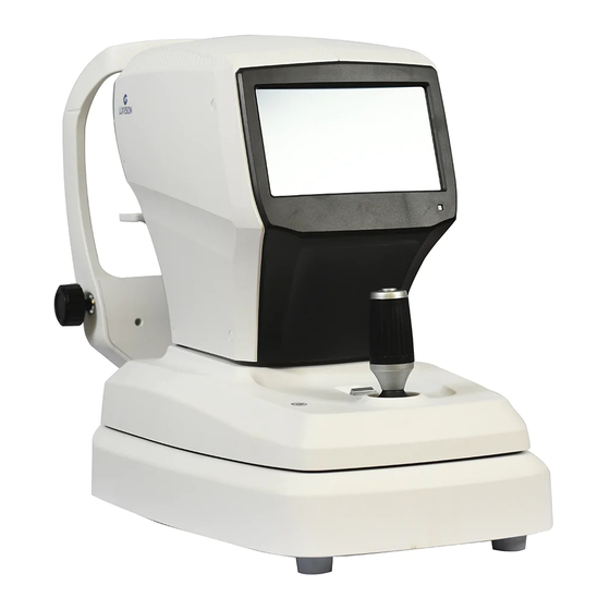
- Page 1 L R K - 70 0 0 A u t o r e f r a c t o r / K e r a t o m e t e r Operation Manual LRK-7000...
- Page 2 Precautions This product may malfunction due to the electromagnetic wave that is generated from mobile phone, two-way radio, machinery controlled wireless and others. Do not place any device that may affect this product nearby. We believe that the contents of this user manual are accurate in overall since they were reviewed carefully.
- Page 3 The spectral output shall be shown for the beam after it exits the instrument. LRK-7000 < Spectrum output of all light source during measurement (maximum light intensity) > “CAUTION – The light emitted from this instrument is potentially hazardous. The longer the duration of exposure, the greater the risk of ocular damage.
-
Page 4: Table Of Contents
CONTENT 1.Introduction ............................1.1.Intended Use ...............................6 1.2.Equipment overview ............................6 1.3.Grade classification and mentioned items ......................6 2.Information regarding safety ......................7 2.1.Introduction .................................7 2.2.Safety indication ..............................8 2.3.Environment related matters ..........................11 2.4.Safety Precautions ............................14 3.Characteristics ........................... 18 4.Precautions during use ........................5.Name and function of each part ....................... - Page 5 8.3.2. Automatic measurement mode ............................49 9.Other mode ............................9.1. SIZE mode (pupil diameter measurement) ...................... 50 9.2. DISPLAY mode ..............................53 9.3. User SETUP mode ............................55 9.3.1. List of setup items & Initial ..............................55 9.3.2. Initial setting ....................................55 9.3.3.
-
Page 6: Introduction
1.Introduction 1.1.Intended Use The Auto Ref/Keratometer LRK-7000 is intended to be used to measure the refractive power of the eye. 1.2.Equipment overview Automatic eye examination refractive power measurement device, LRK-7000 is the equipment that measures refractive power of patient’s eyeball to show Sphere (SPH), Cylinder (CYL) and Axis (AXS) information. -
Page 7: Information Regarding Safety
2.Information regarding safety 2.1.Introduction Safety is everyone’s obligation and responsibility. Safe use of this device is important for everyone involved - installers, users, operators and device managers. It is a must to study and to master this user manual individually prior to installing, using, cleaning, repairing or controlling this device and its accessories. -
Page 8: Safety Indication
2.2.Safety indication The International Electro technical Commission (IEC) announced the symbols that warn when connecting electric medical device’s power or that warn against calamity that may occur. Classification and symbol are as follows. I and O on power switch represent ON and OFF respectively. - Page 9 Alternating Current (Courant alternative) Temperature Limitation (Limitation de température) Keep DRY (Garder au sec) WEEE mark Disposal of your old appliance When this crossed-out wheeled bin symbol is attached to a product it means the product is covered by the European Directive 2002/96/EC.
- Page 10 Warning: Crushing or insert of hand (Attention: écrasement ou insertion de la main) CE Mark (Marque CE) CE for RoHS RoHS Detective Compliance 2011/65/EU (CE pôr RoHS Conformité à la directive RoHS 2011/65 / UE) Atmospheric pressure limitation (Limitation de pression atmosphérique) Humidity limitation (Limite d'humidité) Stack direction...
-
Page 11: Environment Related Matters
Use no hooks (N'utilisez aucun crochet) Consult instructions for use (Consulter les instructions d'utilisation) COM Connector cable Symbol (COM Connector cable Symbole) Serial Number Symbol (Symbole du numéro de série) 2.3. Environment related matters The following environment for operation and storage: Place where device comes directly into contact with moisture (do not operate the device with wet hand) Place where device is exposed directly to sunlight. - Page 12 Where there is a hot equipment nearby. Where the humidity is extremely high or there is a ventilation problem. Where the machine is exposed to excessive shocks or vibrations. Where the machine is exposed to chemical material or explosive gas. Be cautious so that things like dust and metal do not fall inside the machine.
- Page 13 This instrument must be followed by these following conditions: As for the environment when using the device, maintain temperature of 10 ~ 40 ℃, humidity level of 30 ~ 75 % and atmospheric pressure of 800 ~ 1060 hpa. As for the environment when transporting the device, maintain temperature of -40 ~ 70 ℃, humidity level of 10 ~ 95 %, and atmospheric pressure of 500 ~ 1060 hpa.
-
Page 14: Safety Precautions
2.4.Safety Precautions BEFORE USE, READ THIS MANUAL The safety precautions and operating procedures must be thoroughly understood prior to operation of the device. The device complies with ISO 10342 subclause 4: 2010 (Ophthalmic instruments – Eye Refractometers) 10343 subclause 2009 (Ophthalmic instruments Ophthalmometers). - Page 15 Device management by customer should be carried out as explained in the user or service manual. Management that requires more sophisticated skill set can be carried out only by US Ophthalmic LLC service technician or a person with comparable qualifications. Manufacturer assumes responsibility for this device’s safety, reliability and performance only when the following conditions are satisfied: (1) When this device was installed at a viable space in accordance to this manual’s regulations, and (2) when this device was used and maintained...
- Page 16 Do not block device’s hole for heat radiation. Turn off the power immediately and take out the plug when there is smoke, spark, abnormal noise or smell. IEC standard needs to be satisfied with in order to connect an outside device with input/output signal or other connector.
- Page 17 CAUTION For use of equipment in rated voltage less than 125Vac, minimum 6A, Type SJT or SVT, 18/3AWG, 10A, max 3.0m long: One end with Hospital Grade Type, NEMA 5-15P Other end with appliance coupler. For use of equipment in rated voltage less than 250Vac, minimum 6A, Type SJT or SVT, 18/3AWG, 10A, max 3.0m long: One end terminated with blade attachment plug (HAR) Type, NEMA 6-15P.
-
Page 18: Characteristics
3.Characteristics It is possible to carry out both refractive power and corneal curvature measurement with one machine. It is possible to measure even the myopia since the refractive power measurement range is very broad ranging from –30 D to +25 D. When measuring refractive power, it is possible to measure up to a minimum pupil diameter Ø2.0 Fog and mist technique that is applied to the internal fixation Target enables increasingly accurate measurement by ensuring natural and comforting feel for the patient’s eyes. -
Page 19: Precautions During Use
9. When LRK-7000 is not used for a long time, separate the power and cover it with the dust cover. 10. When using this equipment under normal state, then the proper location is as shown below. -
Page 20: Name And Function Of Each Part
5.Name and function of each part 5.1.Key part [Front part]... - Page 21 1. Eye height mark: indicates the height that patient’s eyes should be placed 2. Stage fixation lever: for fixating stage 3. Movement indicator lamp: indicates whether the device power is turned on 4. Display monitor: indicates measurement screen and movement state 5.
- Page 22 [Back part] 1. Forehead rest: location for placing the forehead to prevent test subject from moving the face (Type B attachment part) 2. Measuring window: object lens for measuring the image that is formed in the eye retina 3. Chin rest: location for placing the chin to prevent test subject from moving the face (Chin rest paper: Type B attachment part) 4.
- Page 23 [Lower part] 1. Power supply socket (Fuse holder): Socket that connects with the outside power plug (250V T3.15AL) 2. Serial interface connector: Connector for connecting outside device connector 3. RGB connector: Connector for connecting with the outside monitor of the RGB method 4.
-
Page 24: Main Measurement Screen Button Explanation
5.2. Main measurement screen button explanation [Front part’s switch] (MODE) button: Main measurement mode Button for modifying (REF, KER, K&R,). (MANUAL) button: Button for selecting whether to carry out automatic measurement (Number is frequency) (MANUAL, AUTO-3, AUTO-5, AUTO-A) (COLOR) Button: Button for viewing to color observation mode... - Page 25 (Retro-ILL) button: Button for viewing to retro-illumination mode (SIZE) button: button for measuring to pupil diameter (CYLINDER) Button: Button that reverses cylinder value’s sign (+ => -, - => +) (DATA CLEAR) Button: Button that deletes measurement result. (PRINT) Button: Button that prints measurement result. (SETUP) button: Button for converting to the user SETUP screen.
-
Page 26: Equipment Installation And Preparation For Measurement
6.Equipment installation and preparation for measurement 1. Unlocking stage part’s lock 1 (Clamping bolt) Loosen up the ‘Clamping bolt’ that is at the backside of this device’s lower part by turning it to the counter clock-wise direction, and convert the stage fixation lever that is at the joystick’s backside into the UNLOCK direction. - Page 27 [Unlocking stage part’s lock2 (Body locks)] 3. Access to the power cable - Place LRK-7000 on a table. - Make sure the POWER switch of the instrument is OFF - Put in the power cable into the power connector at the main body’s lower part.
- Page 28 - Pull out the pressing pin on the left and right sides. - Fit in the pressing pin by putting it into the left and side holes of the chin rest paper. - Attach the chin rest paper where pressing pin was fit in, onto the slip. [Chin rest paper] 5.
- Page 29 7. Transmission to other device To transmit measurement result to other device via wired means, connect the cable to this device’s connector for serial interface, and prepare other device. Normally, equipment that gets connected to this eye examination device include the PC that has US Ophthalmic LLC digital reflector, lens meter and software for management provided by a third party built in.
-
Page 30: Measurement Method
7.Measurement Method 1. Turning the main body’s power ON Turn on the power switch. Measurement screen appears when system check is completed. NOTE If the measurement screen that is shown below does not appear on the monitor screen, turn off the power and turn on the power switch on again after 10 seconds. If the measurement screen does not appear, contact the US Ophthalmic LLC distributor. - Page 31 Selecting the Measurement mode This instrument has the measurement modes. (Initial value: REF). REF (REF single measurement) KER (KER single measurement) K&R (KER/REF continuous measurement) [Measurement mode] 3. Height adjustment of patient Have patient sit at the front part of the device. Adjust device’s electric table or chair’s height so that the patient can sit comfortably.
- Page 32 - Adjust the chin rest height by chin rest control knob until the eye height mark of the chin rest reaches the same height as the patient’s eye - confirm that the height mark of the measuring window is at the height of the patient's visual line Eye height mark Eye height mark of Measuring window...
- Page 33 CAUTION Do not place your hand or finger in between stage and Base. Moreover, avoid having patient place his or her hand or finger either. Hand or finger may get injured. Use the operation lever to pull up the main body to the front of the user. Adjust to the left and right while pulling the operation lever to the front slowly so that patient’s right eyes appear at the monitor screen’s center.
- Page 34 [Height adjustment] Adjust by turning the operation lever ➢ [Left and right adjustment] Lean the operation lever to the left and right to adjust so that the ➢ outer arrangement ring gets aligned to the Mire Ring’s location [Focus adjustment] Lean the operation lever, front and back to adjust the focus so that the Mire ➢...
- Page 35 NOTE If trying to adjust by leaning the operation lever is not sufficient, adjust by pushing the stage to the front, back, left and right. - When carrying out refractive power measurement continuously, then there may be margin of error when it comes to measurement in case of patient that finds intervention of accommodation force easy.
- Page 36 [Too far] [Location and Focus are correct]...
-
Page 37: Measurement
8.Measurement 8.1. Refractive power measurement mode (REF mode) This is the mode that measures refractive power by itself. - REF mode selection: Set in a way that the measurement mode indicator section on the screen turns into “REF” mode. Right side measurement Left side measurement Measurement mode indication [REF mode screen]... - Page 38 Mode gets converted to manual measurement mode when you press on the Auto button while in the automatic measurement mode. It is possible to stop automatic measurement function when “Auto Measurement” category is selected as “OFF” while in the user Setup mode. (Refer to “9.5. User SETUP mode”...
- Page 39 ④ Repetitive measurement Measure repeatedly according to need. The latest measurement value is indicated every time measurement takes place. Up to 10 measurement frequencies (excluding measurement failure) are indicated for each of the eyes on the left and right. It is possible to see up to the 10 latest measurement values on the DISPLAY mode’s screen. ⑤...
- Page 40 NOTE - Value measured until now is removed when printing is carried out. - Printed text changes in a light manner since print is a thermal record. Copy when you want to keep measurement data for a long time. [Example of a printed page]...
-
Page 41: Automatic Measurement Mode
8.1.2. Automatic measurement mode NOTE The automatic measurement mode is composed of optimum measurement conditions and can be measured reliably. If the patient's eyes move and it is difficult to measure, press the measurement button on the joystick. The mode gets converted to automatic measurement mode when MANUAL button is pressed on while in the manual measurement mode. -
Page 42: Message List
[REF automatic measurement mode indicator screen] ③ Measurement of the other eye. Move the stage to the right side to measure the left eye using the same procedure. When the measurement of the two eyes is complete, PD value is indicated on the monitor screen automatically. -
Page 43: Corneal Curvature Measurement Mode (Ker Mode)
"CHINREST UP" Move chinrest up. "DATA TRANSMITTING" Measurement data of LRK is being transmitted to external. "DATA PRINTING" Measurement data of LRK is being printed. "HLM DATA PRINTING" Measurement data of LM is being printed. "HDR DATA Measurement data of LM is being transmitted to external. TRANSMITTING”... - Page 44 Outer line arrangement ring Pupil (Minimum pupilloscope Iris [KER mode indicator screen] ③ Carry out the process using the same process as that of the (repetitive measurement), (measurement of the opposite eyes) in the 8.1.1 refractive power measurement mode. ④ Print the measurement result using the process that is like the (printing) process while at the 8.1.2 refractive power measurement mode.
- Page 45 [Example of a printed page]...
-
Page 46: Message List
NOTE 8.2.2. Automatic measurement mode The automatic measurement mode is composed of optimum measurement conditions and can be measured reliably. If the patient's eyes move and it is difficult to measure, press the measurement button on the joystick. The mode gets converted to automatic measurement mode when MANUAL button is pressed on while in the manual measurement mode. -
Page 47: Continuous Corneal Curvature / Refractive Power Measurement Mode (K&R Mode)
8.3. Continuous corneal curvature / refractive power measurement mode (K&R mode) This is the mode for carrying out the corneal curvature measurement and refractive power measurement continuously. - K&R mode selection: Set so that the measurement mode indicator section on the screen becomes “K&R”... - Page 48 Operation process that is the same as that of the (repetitive measurement), (measurement of the ③ opposite eyes) was executed in the 8.1.1 refractive power measurement mode. Prints measurement result through the process that is the same as that of the (printing) in the 8.1.1 ④...
-
Page 49: Automatic Measurement Mode
It is possible to designate symbol of astigmatism refractive power in the measurement mode that includes refractive power measurement. It is possible to designate in the user Setup mode. Moreover, it is possible to indicate Refractive power’s measurement data following VD value in the measurement mode that includes refractive power measurement. -
Page 50: Other Mode
9.Other mode 9.1. SIZE mode (pupil diameter measurement) This is the mode that measures pupil’s diameter. 1. Press on the button in the main measurement mode. Then, SIZE mode gets selected when the SIZE button is pressed on. 2. Adjust location and focus the image of the eye to be measured clearly. [Size mode indicator screen (1)]... - Page 51 Pupil Vertical bar Right eye Cornea Border Button to move the left vertical bar Button to move the right vertical bar Indicates measurement and average values [Size mode indication screen (2)] 3. Measurement location and focusing Ask patient to watch fixating target at the inside. Move the operation lever to adjust the location so that the pupil is in between two vertical bars.
- Page 52 Left button and button adjust the movement of the left bar while button of the right side button adjust the movement of the right side bar. Measurement value is indicated on the monitor. Measurement value is saved automatically. Measured value gets indicated at the Pupil Size at the screen’s center lower part. Average of the recent two measurement values is indicated in the “Avg Size”...
-
Page 53: Display Mode
9.2 DISPLAY mode It is possible to see the measurement results that are saved in the memory (up to 10 for the left and right eyes). The mode changes into the DISPLAY mode when the DISP button is pressed on after pressing on the button at the main measurement mode. - Page 54 : This is the screen that shows Refractometry measurement result. : This is the screen that shows Keratometry measurement result. : Button for deleting saved DATA and that returns to the measurement mode. : Button for printing saved DATA. 1. Refractometry measurement result Indicates the latest 10 measurement results (refractive power).
-
Page 55: User Setup Mode
9.3. User SETUP mode It is possible to adjust various setups related to the measurement, printer output and others. You can go into the user SETUP mode by pressing on the (SETUP MODE) button in the main measurement screen. 9.3.1. List of setup items & Initial Setup items are categorized in to 8 large indexes - REF - KER... - Page 56 mm/D mm / D / AVG STEP 0.05 / 0.12 / 0.25 0.05 INDEX 1.332 / 1.336 / 1.3375 1.3375 AUTO MEASUREMENT Off / On(3) / On(5) /On(A) On(3) AUTO START AUTO TRACKING Off / On BPS (COM1) 9600 / 57600 / 115200 115200 RS232 PROTOCOL Off / V1 / V2/ Ext...
-
Page 57: Detailed Description Of Setting
LCD COLOR COOL ~ O ~WARM TEMPERATURE EXT. LED Off / On (RETRO-ILL) COUNT Off / On PATIENT NUMBER Control 00000 LANGUAGE English English BEEP SOUND Off / On INITIAL MODE REF / KER / K&R SLEEP MODE Off / 3min / 5min /10min 3min AIMMING DOT Off / On... - Page 58 [Method for entering into the measurement mode] Press on the button to save the contents automatically, and the mode returns to the main measurement mode. [Setup mode information]...
- Page 59 [Contents of the category]: 1/2 Page 1. REF (cornea measurement) VD (0.0/12.0/13.75/15.0) : Distance between corneal apex and corrective lens CYLINDER (-/+/Mix) : Astigmatism marking form STEP (0.01/0.12/0.25) : Unit for indicating spherical prescription and astigmatism prescription FOGGING (1Time/Always) : Select whether to carry out the mist execution frequency once or every time when carrying out continuous measurement DIOPTER-SHIFT (0.00) : Set up the applicable value to correct the diopter measurement value...
- Page 60 AX ····· ····· ····· ··· mi nimum cornea refractive power’s angle AR ··················averag e curvature radius CY ··················cornea as tigmatism prescription AX ····· ····· ····· ··· cor nea astigmatism’s angle STEP (0.05/0.12/0.25) : Unit for indicating cornea refractive power and cornea astigmatism prescription INDEX (1.332/1.336/1.3375) : Selection of cornea equivalence’s refractive power AUTO START (automatic function)
- Page 61 : Select the target of second communication port. NOTE - For the users who want LRK-7000 is connected with two devices at the same time, we prepare the RS232 Y CABLE. - If LRK-7000 is connected with only one device, set [RS232 PROTOCOL (COM2)] off, and do not care about all of “COM2”...
- Page 62 [Case 1. Digital refractor + LM] 1) Connect a digital refractor to COM1 of the RS232 Y CABLE. 2) Connect HLM to COM2 of the RS232 Y CABLE. 3) Set [BPS (COM1)], [RS232 PROTOCOL (COM1)] and [MODE (COM1)] for the target digital refractor.
- Page 63 4) Set [LM PRINT] on. 5) Set [RS232 PROTOCOL (COM2)] on. 6) Set [BPS (COM2)] for target LM. 7) Select [LM] for [MODE (COM2)] 5. PRINT (printing setting) AUTO PRINT (Off/On): When measurement takes place in automatic measurement mode, measurement result is printed automatically when the measurement is completed in sequence for the left and right eyes.
- Page 64 DATE (YY/MM/DD): Modification of the setting for date (year/month/day) (Scope: Y = 00 ~ 99, M = 01 ~ 12, D = 01 ~ 31 (1 ~ 28 when the M is February)) TIME: modify setting for time (hour/minute/second) (Scope: H = 00 ~ 23, M = 00 ~ 59, S = 00 ~ 59) 6.
- Page 65 8. ETC (other setting) LANGUAGE (English/Chinese): Selects the language that is indicated on the screen and printer output door. BEEP SOUND VOLUME (Off/Low/Mid/High): Sets up the Beep sound output to small, average and large. INITIAL MODE (REF/KER/K&R): selection of initial measurement mode. SLEEP MODE (Off/3min/5min/10min): Sets up the time required for entering into the power- saving mode AIMMING DOT (Off/On): The center position of the patient's eye is indicated by a yellow dot.
-
Page 66: Input Method
9.4. Input method [Other (text) input] [Text input] : Converts capital letter/small letter input mode. : Deletes all the input texts. : (Back Space) deletes only one letter in front of the cursor. : Converts the space in between the first and second lines. : Saves input text. - Page 67 [Other (number) input] [Number input] Range: Minimum ~ maximum scope that can be input (Does not get saved when the scope is deviated from, and the warning message, “Out of Range!” appears.) : Deletes the last number. : Deletes all the numbers. : Saves number and exists number input mode.
-
Page 68: Self-Diagnosis And Maintenance/Repair
10.Self-diagnosis and maintenance/repair 10.1. REF / KER Accuracy check Remove chin rest page, and fit in the pressing pin after aligning the hole at the Model Eye’s lower part with chin rest’s hole. Perform the measurement and compare with the display value at the bottom of the model eye. (STEP 0.01) Perform the accuracy check at regular intervals. -
Page 69: Replacing
10.2. Replacing 10.2.1. Printer paper Replace the paper for the printer immediately when red line appears on the paper. 1) Pull the handle to open the printer cover. 2) Take out the remaining paper roll to the outside. 3) Fixate the new paper by pushing it into the printer. And, adjust the length to a degree that can be discharged as the paper gets fit into the paper discharge of the cover.(10~15cm) Close the printer cover and make sure the printer paper is in the center of the printer cover. -
Page 70: Chin Rest Paper
NOTE Be sure that printer paper is not loaded in a tilted angle and that the core of the roll is properly placed. Printer paper may not be fed properly. 10.2.2. Chin rest paper 1) Take out two pins from the chin rest. 2) Push in the pin into the hole that is found on the chin rest paper. - Page 71 For low-level disinfection(normally), the patient contact parts may be wiped with any of the • following low-level disinfectants Methods to disinfect to LRK-7000 are as below: - Dry heat - Mechanical cleaning with disposable wipe / sterile gauze...
-
Page 72: Cleaning
10.4. Cleaning 10.4.1. Cleaning the measuring window When the measuring window gets fingerprints or dust on it, the reliability of the measured values is impaired substantially. Check for dirt on the measuring window before use, and then clean it if it is dirty. 1) Blow off and dust on the measuring window with a blower. -
Page 73: Cleaning The Forehead Rest And Chin Rest
2) If the mire ring and the cover are noticeably stained, wipe the surface with a damp cloth which is moistened in a tepid water solution of neutral detergent. CAUTION Do not clean plastic parts with solvents. Benzene, thinner, ether and gasoline may cause discoloring and decomposition. -
Page 74: When Moving Equipment Installation Place
2) Check list When Remedy - The power cord may not be correctly connected. Reconnect it securely The LCD does not turn - Check whether proper voltage is applied to the power outlet. - The power switch may not have been turned on. Check the power switch. -
Page 75: Information Needed For Servicing
Repair: Contact the distributor after preparing the information on the following matters when the problem is not resolved even after taking the measures described on 10.5 Phase. equipment name: LRK-7000 equipment’s serial number: number on the name plate that is comprised of numbers and letters(SN) - Page 76 If any problem persists or the instrument is damaged or malfunctioning, contact US Ophthalmic LLC or local distributor for service with the following information. • Name of the instrument: Auto Ref/Keratometer LRK-7000 • Serial number of the instrument: refer to the 9-digit number on its product label or name plate •...
- Page 77 US Ophthalmic LLC Tel: +786-621-1842 9990 NW 14th ST STE 105, Doral FL 33172 Fax: +786-621-0521 http://www.usophthalmic.com e-mail: info@usophthalmic.com EU Representative Lotus Global Co., Ltd. 1 Four Seasons Terrace Tel:+0044-20-75868010 West Drayton,Middlesex +0044-20-709961611 London,UB7 9GG Fax: +0044-20-7906187 United Kingdom CAUTION Environment pollution may result when the device or lithium battery is discarded recklessly since this device uses lithium battery.
-
Page 78: Key Specs
12.Key specs Measurement mode Cornea/curve continuous measurement (K/R mode) Curve measurement (REF mode),cornea measurement (KER mode) Curve measurement Distance between vertex 0.0, 12.0, 13.75, 15.0 of cornea (VD) Spherical prescription (SPH) -30.00 ~ +25.00 D (in case of VD = 12 mm) Astigmatism prescription(CYL) 0.00 ~ ±12.00D (0.01/0.12/0.25 D unit) Astigmatism axis angle(AX) - Page 79 (Increments: 0.05/0.12/0.25 D) Prescription Cornea astigmatism 0 ~ 180˚ (1˚ unit) axis angle Cornea diameter 2.0 ~ 14.0 mm (0.1 mm unit) measurement The measuring range is in accordance with Code A, ISO 10343 and the measuring accuracy in accordance with Code 2, ISO 10343.) Auto travel distance Up and down ±...
- Page 80 LRK-7000 LRK-7800 Function Description Measurement of diopter ○ ○ Cornea measurement ○ ○ K&R Continuous Keratometry & Refractometry ○ ○ Distance between vertex of cornea ○ ○ Pupil distance ○ ○ SIZE Pupil diameter measurement ○ ○ The mode that can observe eye lens by Retro-ILL ○...
-
Page 81: Accuracy
13.Accuracy - The accuracy specifications are based on the results of model eye testing performed in accordance with ISO10342 Ophthalmic instruments- Eye Refractometers, ISO10343 Ophthalmometers. 1) Refractometry Maximum Criterion Measuring range Test device Tolerance scale interval 0.00D~±10D 0D, ±5D, ±10D ±0.25D 0.25D ±15D... -
Page 82: Accessories
14.Accessories [Accessories] 1. Power cable (AC 220 V / 60 Hz power code, 1.5m) ···················································1 2. Model Eye ······································································ ········································1 (SPH: –2.50D~-2.75D, CYL: -1.25D~-1.50D, R1: 7.95~8.00, R2: 7.78~7.83) 3. Chin rest paper (100 pages) ············································· ···························· ············1 4. Printer page(roll) ······································································································2 5. - Page 83 LRK- 7000 LM-1 8. Wind-blower··········································································································1...
-
Page 84: Emc Information
Guidance and manufacturer´s declaration – electromagnetic immunity The Model LRK-7000 is intended for use in the electromagnetic environment specified below. The customer or the user of the Model LRK-7000 should assure that it is used in such an environmen t. IEC 60601... - Page 85 Guidance and manufacturer’s declaration – electromagnetic immunity The Model LRK-7000 is intended for use in the electromagnetic environment specified below. The c ustomer or the user of The Model LRK-7000 should assure that it is used in such an environment.
- Page 86 Portable and mobile RF communications equipment should be used no closer to any part of the Model LRK-7000, including cables, than the recommended separation distance calculated from the equation applicable to the frequency of the transmitter.
- Page 87 If the measured fiel d strength in the location in which the Model LRK-7000 is used exceeds the applicable RF complia nce level above, the Model LRK-7000 should be observed to verify normal operation. If abnormal performance is observed, additional measures may be necessary, such as re-orienting or relocati ng the Model LRK-7000.
- Page 88 80 MHz to 800 MHz 800 MHz to 2.7 GHz 150 kHz to 80 MHz Rated maximum d= [ d= [ ] √ �� ] √ �� d= [ ] √ �� output of transmitter �� �� �� 0.01 0.12 0.12 0.23 0.38...
- Page 89 equipment should be us ed no closer to any part of the device, including cables, than the recommended separation distance calculated from the equation applicable to the frequency of the transmitter. Recommended separation distance �� 1720 �� = √�� �� Where P is the 1845 maximum output...
-
Page 90: Electrical Construction Diagram
Note 1: These guidelines may not apply in all situations. Electromagnetic propagation is affected by absorption and reflection from structures, objects and people. WARNINGS! • This device should not be used in the vicinity or on the top of other electronic equipment such as cell phone, transceiver or radio control products. - Page 91 L R K - 7 0 0 0 A u t o r e f r a c t o r / K e r a t o m e t e r 9990 NW 14 Street | Suite 105 | Doral, FL 33172 Telephone: 888.334.4640...
Need help?
Do you have a question about the LRK-7000 and is the answer not in the manual?
Questions and answers