
Related Manuals for MCC EM-1


Summary of Contents for MCC EM-1
- Page 1 T-299 Manual OPERATION AND SERVICE SPLIT SYSTEMS Generation 4 & 5 T-299 Manual REV. 08/2012 © 2012 Mobile Climate Control...
- Page 2 Never attempt to apply heat or open flame to a refrigerant cylinder. High temperatures can raise the cylinder pressure to dangerous levels. MCC recommends using a heat blanket to increase the internal temperature of the refrigerant cylinder, greatly increasing the transfer of refrigerant to the bus air conditioning system.
- Page 3 Do not bypass any electrical safety devices, e.g. bridging an overload, or using any sort of jumper wires. Problems with the system should be diagnosed, and any necessary repairs performed, by qualified service personnel. When performing any arc welding on the vehicle, disconnect the vehicle battery. In case of electrical fire, extinguish with CO (never use water).
- Page 4 CAUTION Use only the exact oil specified by the compressor manufacturer. Use of oil other than that spe cified will void the compressor warranty. Safety --3 © 2012 Mobile Climate Control T-299 Rev. 08/2012...
- Page 5 Table of Contents SAFETY SUMMARY ............. . . Safety -1 SPECIFIC WARNINGS .
- Page 6 Table of Contents 2.8.2 Variable Speed Control Operation ............2.8.3 Total Control - Gen 5 Operation .
- Page 7 Table of Contents 4.6.2 Preparation ............... . 4.6.3 Procedure For Evacuation and Dehydrating System (Triple Evacuation) .
- Page 8 List of Tables Table 1-1 Additional Support Manuals ..........Table 3-1 Evaporator Current Draw (GEN 4) .
- Page 9 ....... Figure 5-4 GEN 4 System Schematic - EM-1 With CM-2/3 - Tie-In .
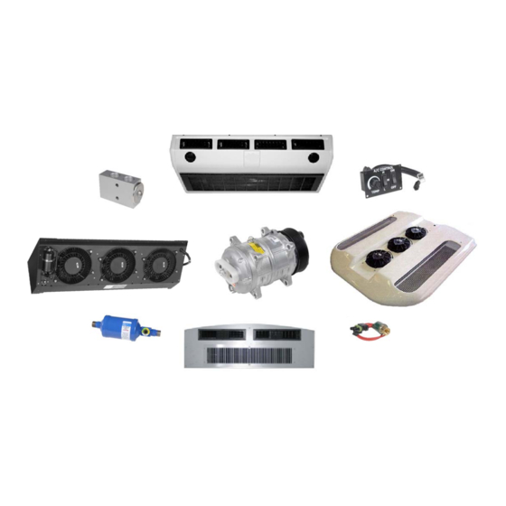
- Page 10 CM-7 & CM-11 rooftop condensers data tag support manuals are listed in Table 1-1. location. The CM-7 and CM-11 rooftop condensers are no longer available from MCC. A Split System normally includes an Evaporator(s), a Condenser(s) a Compressor(s) and interconnecting...
- Page 11 Figure 1-1 Condenser Model CM2/3 - Serial Number Location EM-9 Location Figure 1-2 GEN 4 Evaporator Model - Serial Number Location Figure 1-3 GEN 5 Evaporator Model (All) - Serial Number Location 1--2 © 2012 Mobile Climate Control T-299 Rev. 08/2012...
- Page 12 Figure 1-4 GEN 4, IW-2 & IW-7 - Serial Number Location Figure 1-5 GEN 4, IW-1 - Serial Number Location 1--3 © 2012 Mobile Climate Control T-299 Rev. 08/2012...
- Page 13 Obsolete Tag Figure 1-6 CM-7/11 Rooftop Condensers (No Longer Offered) - Serial Number Location Figure 1-7 KR-2/KR-3 Rooftop Condensers - Serial Number/PID Location 01- 22- 07 Figure 1-8 System Requirements Label 1--4 © 2012 Mobile Climate Control T-299 Rev. 08/2012...
- Page 14 Conditioning application. the permanent magnet evaporator blower motors. Compressor - The compressor is a belt driven, Max System - An MCC system installed along with high-pressure pump, which circulates the refrigerant an existing OEM system. The systems operate through the evaporator and condenser . The independent of each other.
- Page 15 Most MCC systems use R134a. Refrigerant - A refrigerant is a material that is used Compressor...
- Page 16 FREEZE-UP THERMOSTAT: KR-4: Single shafted, permanent magnet, 12 VDC (12.5 Nominal) continuous duty, single speed GEN 4 Series Freeze-Up Thermostat: Cut-out at 26° motors. F, ±1.5° F. Cut-in at 34° F, ±1.5° F. Pre-set at Full Load Amps: 7 Amps @ 1900 RPM @ 12.5 factory (Adjustable).
- Page 17 NOTE The low pressure, low temperature liquid that flows into the evaporator tubes is colder than the air that is The new style micro-channel condensers are circulated over the evaporator tubes by the fitted with receiver-driers instead of evaporator fans. Heat transfer is established from the filter-driers.
- Page 18 EVAPORATOR COIL (GEN 5 Location) EVAPORATOR ASSEMBLY SUCTION LINE LIQUID LINE SUCTION ACCESS PORT SIGHT GLASS (GEN 5 FILTER DRYER Location) DISCHARGE RECEIVER DRIER ACCESS PORT CONDENSER COIL (GEN 4 Location) DISCHARGE LINE CONDENSER ASSEMBLY COMPRESSOR NOTE: MICRO--CHANNEL DISCHARGE LINE CONDENSER HPS IS LO- CATED ON RECEIVER--DRIER LIQUID LINE...
- Page 19 1.9 HEATING CYCLE (If Applicable) Engine coolant is circulated through the heating circuit by the engine and/or auxiliary water pump. When the heat valve is opened, engine coolant flows The optional heating circuit component furnished through the heater coil. Heat is transferred from the by Mobile Climate Control is the side or rear glycol flowing in the tubes to the air flowing over the mounted evaporator heater core.
- Page 20 SECTION 2 OPERATION 2.1 OPERATING INSTRUCTIONS 2.2.3 Thermostat Control The thermostat controls the temperature within the Before attempting to operate the system, power passenger compartment by switching system must be available from the vehicle battery. If the components on and off. engine is not running, start the engine.
- Page 21 2.3 FLORIDA CONTROL (TEMPCON) This controller is normally used in school buses located within the state of Florida, but not limited to that area (See Figure 2-3). This controller is wired to an electrical control board. The controller consists of: a.
- Page 22 2.5 TOTAL CONTROL Press the + or - keys to bring the desired set point into the display. The Total Control system consists of a Key Pad If the set point is below the inside temperature, the Display (See Figure 2-5) wired to an Electrical cooling will come on.
- Page 23 When in parameter, if no key is pressed for 5 seconds, the display will go back to default mode showing temperature set point. Cooling 2 Modification Of Null Band Parameter P01 Set Point + 1/2 Null Band Press and hold + and - key simultaneously for 5 seconds to access parameters programming mode.
- Page 24 2.6 GEN 4 - WITH TOTAL CONTROL, UNIT OPERATING 2.8.1 Three Position Switch Operation INSTRUCTIONS With Power to the ignition circuit breaker (see The controller is configured to operate with the Figure 5-3) and battery circuit breaker the fan speed GEN 5 unit by default.
- Page 25 2.8.2 Variable Speed Control Operation energize the clutch. Energizing the clutch starts the compressor. With Power to the ignition circuit breaker and Two seconds after starting the compressor, the battery circuit breakers (see Figure 5-6) the fan speed microprocessor will provide power from terminal switch is brought to the desired speed position to EFM+ to energize the high speed relay (HSR).
- Page 26 If low speed is selected, the microprocessor will If high speed is selected, the microprocessor will provide power from terminal EFM+ to energize the provide power from terminal EFM+ and BPV to low speed relay (LSR). Energizing LSR closes it's energize the low speed relay (LSR), medium speed normally open contacts to provide power from the relay (MSR and high speed relay (HSR).
- Page 27 (2.2°C) NOTE Controller parameters are factory set, and (1.1°C) cannot be modified without factory au thorization. If necessary, contact MCC's Technical Service Hot Line for assist ance (800-450-2211) . 2.9.1 Controller Operation Once the EnviroMATE controller is powered with 12VDC, supplied by the Bus OEM, the system can...
- Page 28 Fan speeds can be controlled manually by pressing circuit opens, the controller will de-energize the the Vent Key (Item 2 in Figure 2-8), an LED light compressor clutch relay, and the condenser fan relay will activate in the corner of the Vent Key . After for a minimum time of 1 minute, or until the open pressing the Vent Key, use the Increase/Decrease circuit closes.
- Page 29 2.9.8 Alarm Descriptions FAILURE DESCRIPTION Pressure switch failure Internal temperature sensor failure External temperature sensor failure Battery lower 10 VDC failure Alternator failure 3 Pressure switch failures (HA) in 30 min. Discharge pressure failure Suction pressure failure Figure 2-9 EnviroMATE Alarms (Single Zone) 2--10 ©...
- Page 30 Zone 2 NOTE Controller parameters are factory set, and cannot be modified without factory au thorization. If necessary, contact MCC's Technical Service Hot Line for assist After a few seconds, the display will return to the set ance (800-450-2211) .
- Page 31 2.10.2 Evaporator Fan Operation (Automatic) 2.10.4 Cooling Mode When Cooling Mode is selected (Item 7 in Evaporator fan speeds are controlled automatically Figure 2-10), The green LED light will display in according to the chart shown below. There are 3 fan upper left corner of Key by the “Snowflake”...
- Page 32 2.10.5 Heating Mode (If equipped) compressor clutch relay, and the condenser fan relay will remain energized to lower system pressure. The The EnviroMATE Controller has the ability to compressor relay will remain open for a minimum control output to a heat control valve and boost time of 1 minute, or until high pressure switch circuit pump (OEM supplied) to supply heat provided by closes.
- Page 33 2.10.9 Alarm Description (Dual Zone) Failure Description Action Temperature zone 1 sensor fail Assume the temperature of 72°C Temperature zone 2 sensor fail Assume the temperature of 72°C Alternator failure Only ventilation enabled Voltage lower than 10V ---------------------------- Low pressure failure (Group 1) Turn OFF compressor 1 High pressure failure (Group 1) Turn OFF compressor 1...
- Page 34 SECTION 3 TROUBLESHOOTING 3.1 INSUFFICIENT OR NO COOLING Bubbles in the sight glass may indicate an undercharge of refrigerant and/or a restriction in the 3.1.1 Preliminary Checks liquid line. If the charge is low, check the system for leaks; repair if necessary and charge the system with Make certain that the evaporator filters are not the proper amount of refrigerant.
- Page 35 LOW - (Red) MED. - (Yellow) HIGH - (Orange) HIGH PERF. - (Black) 12.5 VDC 8.6 Amp 14.4 Amp 18.5 Amp 30 Amp EM-1 13.5 VDC 10 Amp 15 Amp 19.4 Amp 32 Amp 24.5 VDC 7.8 Amp 10.7Amp 12.7 Amp 16 Amp 12.5 VDC...
- Page 36 SPEED SETTING (3) AND AMP DRAW MODEL VOLTAGE LOW - AMP MEDIUM - AMP HIGH - AMP 13.5 VDC 9.7 Amp 17.9 Amp 29.5 Amp EM-1 24.5 VDC 13.5 VDC 8.8 Amp 13.3 Amp 24.3 Amp EM-2 24.5 VDC 13.5 VDC 16 Amp 32.2 Amp...
- Page 37 Table 3-4 GENERAL SYSTEM TROUBLESHOOTING PROCEDURES INDICATION/ POSSIBLE CAUSES TROUBLE SYSTEM WILL NOT COOL Compressor will not run Drive--Belt loose or defective Clutch coil defective Clutch malfunction Low refrigerant charge Compressor malfunction Electrical Malfunction Circuit Breaker Open Relay Defective SYSTEM RUNS BUT HAS INSUFFICIENT COOLING Compressor Drive--Belt loose or defective Compressor defective...
- Page 38 Table 3-4 GENERAL SYSTEM TROUBLESHOOTING PROCEDURES - Continued NO EVAPORATOR AIR FLOW OR RESTRICTED AIR FLOW Air flow through coil blocked Coil frosted over Dirty coil Dirty filter assembly No or partial evaporator air flow Motor running in reverse Motor(s) defective Evaporator fan loose or defective Fan damaged Dirty filter...
- Page 39 Table 3-5 TROUBLESHOOTING ALARM CODES (TOTAL CONTROL) ALARM TITLE CAUSE REMEDY CODE AL 13 Return air sensor. Open circuit or short circuit on Check connections on RAS + and RAS - on the control the return air sensor connec board. Make sure the Red terminal is connected to RAS tion.
- Page 40 Table 3-5 TROUBLESHOOTING ALARM CODES (TOTAL CONTROL) Cont:: AL 47 Not Used Malfunction is detected on AL 48 Heating Valve malfunction the HV output. NOTE If the controller calls for cooling (green led is on), the condenser and evaporator fans are running, but the compressor is OFF without any alarm code, this indicates one of the following has occurred: 1.
- Page 41 SECTION 4 SERVICE WARNING Be sure to observe warnings listed in the safety summary in the front of this manual before performing maintenance on the air conditioning system 4.1 PREVENTATIVE MAINTENANCE SCHEDULE SYSTEM OPERATION a. Daily Maintenance Pre-trip inspection - after starting. (Refer to paragraph 2.7) Check tension and condition of drive belts.
- Page 42 Mobile Climate Control. (Mobile Climate Control P/N 07-00294-00, which includes 2.. R134a Low Side (Suction) Coupler MCC P/N items 1 through 6, Figure 4-1 .) To perform service 07-00307-04 - Connects the air conditioning system using the manifold gage/hose set, do the following: Suction Access Port to the Manifold Gauge Set.
- Page 43 a. Preparing Manifold Gauge/Hose Set For Use WARNING 1.. If the manifold gauge/hose set is new or was exposed to the atmosphere it will need to be To prevent trapping liquid refrigerant in evacuated to remove contaminants and air as the manifold gauge set be sure set is follows: brought to suction pressure before...
- Page 44 (New Location GEN 5) EVAPORATOR COIL NOTE: MICRO--CHANNEL CONDENSER HPS IS LO- CATED ON RECEIVER-- DRIER SUCTION ACCESS SIGHT GLASS RECEIVER/DRIER FILTER DRYER DISCHARGE ACCESS (GEN 4 Location) CONDENSER COIL COMPRESSOR Vacuum Pump Recovery/Recycle Machine Micron Gauge R134a High (Discharge) Side Coupler Manifold Gauge Set R134a Low (Suction) Side Coupler Refrigerant Cylinder...
- Page 45 30 PSIG (R134a). any system include a vacuum pump (6 cfm volume b. Add sufficient nitrogen to raise system pressure displacement - (MCC P/N 07-00176-11) and an to150/200 psig. (10.21/13.61 bar). electronic vacuum (micron) gauge (MCC P/N c. Check for leaks. The recommended procedure for 07-00414-00).
- Page 46 4.6.3 Procedure For Evacuation and Dehydrating b. Air conditioning system operating in high cool 10 System (Triple Evacuation) to 15 minutes. a. Remove all refrigerant using a refrigerant recovery c. Compressor discharge (head) pressure a minimum system (Refer to paragraph ) of 150 psig with R134a.
- Page 47 4.9 COMPRESSOR(S) CAUTION If the compressor(s) is inoperative and the system still has refrigerant pressure, recover the refrigerant Unless there was a catastrophic failure, with an approved recovery/recycle machine before such as a blown or ruptured refrigerant attempting repair and/or replacement of the hose, additional oil may not be needed.
- Page 48 Table 4-1 Split System Refrigerant And Oil Charging Table - Thru GEN 4 Evaporator Condenser Recommended Recommended Up to GEN V All Series R134a Charge Oil Charge* EM-1, EM-2, or EM-9 CM-2 5.00 Pounds 10.0 Ounces EM-1, EM-2, or EM-9 CM-11 5.25 Pounds 10.5 Ounces EM-6 CM-2 4.00 Pounds...
- Page 49 CLOSE-UP VIEW COIL FINS Figure 4-1 Micro-Channel Style Condenser Assembly The data listed in Table 4-1 trough Table 4-3 is based on a 20 foot liquid line. Increase the charge by 0.5 pound for each additional 10 feet of liquid line. After determining the approximate charge using the above tables, refer to “System Performance Chart”...
- Page 50 Table 4-5 Mobile Climate Control SYSTEM PERFORMANCE CHART Determine the approximate refrigerant charge using Table 4-1, Table 4-2 or Table 4-3 . Use the following table to determine if the correct charge has been obtained. Table Procedure Your Entry Example Pressure Refrigerant Temp.
- Page 51 Table 4-6 STANDARD TORQUE REQUIREMENTS O-RING SIZE TUBE O.D. * FLARE THREAD ** STEEL TUBING ALUM. TUBING 1/4 inch (.250) 11-13 ft./lbs. 30-35 ft./lbs. 5-7 ft./lbs. 7/16 3/8 inch (.375) 15-17 ft./lbs. 30-35 ft./lbs. 8-10 ft./lbs 9/16 3/8 inch (.375) 18-20 ft./lbs.
- Page 52 Clearance Zone Identification Clearance at Mid Span Figure 4-5 Belt Clearance Requirements 4.12 DRIVE BELT INSTALLATION 4.12.2 Belt Clearance A certain belt clearance needs to be maintained for belt span vibration when installing compressors and 4.12.1 Introduction alternator belts. Figure 4-5 shows the recommended guidelines for clearance.
- Page 53 Incorrect Correct Figure 4-7 Straight-Edge Application Proper use of a straight edge is illustrated in Figure 4-7 . Never use a straight edge on the wide/flat side, as they are not accurate. The thin edge is a straight surface and the only accurate surface. The straight edge must be flush across the face of the pulley.
- Page 54 4.13 RETURN AIR FILTER Notice that new belt tension is higher than in-service or re-tension amount. All new belts require a run-in period. During this period, a new belt will stretch more in a 10 hour run time than the entire life of the NOTE belt.
- Page 55 Disconnect the red and black wire from the terminal block. Ω Ω Ω d. Using a 1/8 inch (EM-1 only) or 3/32 inch Medium High High Performance (EM-2/3/7) Allen handle loosen the set screw securing the motor shaft to the blower wheel. The...
- Page 56 NOTE WARNING If evaporator fan motor is only functioning in 1 or 2 of the 3 speeds, the resistor is bad, There may be liquid refrigerant trapped not the fan motor. behind the block valve. Slowly loosen the fitting and avoid contact with exposed skin or eyes.
- Page 57 NOTE b. Connect an ohmmeter across switch terminals. If the switch is good, the ohmmeter will indicate All microchannel condenser assemblies are no resistance, indicating that the contacts are equipped with a receiver-drier with an closed. integral high pressure switch. c.
- Page 58 To Evaporator Sight Glass Refrigerant “OUT” Connection Moisture Indicator O--Ring Filter Drier--Sight Glass Assembly Flow Label Clamp O--Ring HPS Connection Refrigerant “IN” To Condenser Connection Figure 4-10 Filter Drier Figure 4-11 Receiver-Drier 4--18 © 2012 Mobile Climate Control T-299 Rev. 08/2012...
- Page 59 Table 4-10 R-134a Temperature - Pressure Chart Temperature Vacuum Temperature Pressure ° ° Psig Kg/cm@ PSIG Kg/cm@ ° ° 24.5 1.72 1.69 14.6 37.08 0.49 26.1 1.84 1.80 12.3 31.25 0.42 27.8 1.95 1.92 24.64 0.33 29.6 2.08 2.04 17.00 0.23 31.3 2.20...
- Page 60 SECTION 5 ELECTRICAL SCHEMATIC DIAGRAMS 5.1 INTRODUCTION This section contains Electrical Schematics covering the GEN 4 and GEN 5 systems. Figure 5-3 shows a GEN 4 EM--1 Evaporator with a CM--2/3 Condenser, Figure 5-4 shows a GEN 4 Series EM--1 Evaporator with a CM--2/3 Con- denser tied into an OEM compressor, Figure 5-5 shows a GEN 4 EM--3 evaporator with (2) CM--3 condensers, Figure 5-6 shows a (typical) GEN V evaporator with variable speed controls, Figure 5-7 shows a (typical) GEN 5 sys- tem with Total Control, Figure 5-8 shows a GEN 4 EM--3 with Total Control, and Figure 5-9 shows a (typical) GEN 4...
- Page 61 LEGEND Ground Adjusting Compressor #2 Relay Alternator HGS1 Ampere HGS2 Heat Valve High Pressure Switch Load Battery For Grounding of Low Pressure & Frozen Coil Switch For Comp. #1 Low Pressure & Frozen Coil For Grounding of Low Pressure & Frozen Switch For Compressor #2 Coil Switch For Comp.
- Page 62 5--3 © 2012 Mobile Climate Control T-299 Rev. 08/2012...
- Page 63 5--4 © 2012 Mobile Climate Control T-299 Rev. 08/2012...
- Page 64 5--5 © 2012 Mobile Climate Control T-299 Rev. 08/2012...
- Page 65 5--6 © 2012 Mobile Climate Control T-299 Rev. 08/2012...
- Page 66 5--7 © 2012 Mobile Climate Control T-299 Rev. 08/2012...
- Page 67 5--8 © 2012 Mobile Climate Control T-299 Rev. 08/2012...
- Page 68 5--9 © 2012 Mobile Climate Control T-299 Rev. 08/2012...
- Page 69 5--10 © 2012 Mobile Climate Control T-299 Rev. 08/2012...
- Page 70 5--11 © 2012 Mobile Climate Control T-299 Rev. 08/2012...
- Page 71 5--12 © 2012 Mobile Climate Control T-299 Rev. 08/2012...
- Page 72 GEN 4 - WITH TOTAL CONTROL, 2-5 Adding Refrigerant, 4-6 GEN 4 - WITH TOTAL CONTROL, UNIT AIR CONDITIONING, 1-1 OPERATING INSTRUCTIONS, 2-5 Heat Option, 2-7 CHECKING AND REPLACING HIGH PRESSURE SWITCH, 4-16 HEATING CYCLE , 1-10 High Pressure Switch, 4-16 COMPONENT SPECIFICATIONS, 1-6 COMPRESSORS, 4-7 CONDENSER FAN ASSEMBLY, 4-16...
- Page 73 REFRIGERANT CHARGE, 4-6 Thermostat Control, 2-1 REFRIGERANT RECOVERY, 4-5 Three Position Switch Operation, 2-5 REPLACING BLOCK VALVE, 4-16 TORQUE SPECIFICATIONS - BOLTS, 4-11 RESISTORS, 4-15 TORQUE SPECIFICATIONS - FITTINGS, 4-11 RETURN AIR FILTER, 4-14 TOTAL CONTROL, 2-3 Total Control - Gen 4 Operation, 2-6 Total Control - Gen 5 Operation, 2-6 Total Control Operation, 2-3 SEQUENCE OF OPERATION, 2-5...
- Page 74 MCC products MCC provides exceptional performance in mobile climate comfort. www.mcc-hvac.com Member of MCC Group Certified ISO 9001 and ISO 1 4001. Specifications subject to change without notice. MCC is a registered trademark. T-299 Rev. 08/2012 © 2012 Mobile Climate Control...
Need help?
Do you have a question about the EM-1 and is the answer not in the manual?
Questions and answers