Advertisement
Quick Links
Advertisement

Related Manuals for Black Corporation Deckard's Dream Expander


Summary of Contents for Black Corporation Deckard's Dream Expander
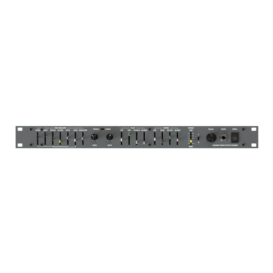
- Page 1 Deckard’s Dream Expander FAQ and Build Guide. DRAFT V1.5 s the Expander do? er provides both MIDI control changes and/or audio effects, to any sources plugged in. Modulator: Audio Only olo/Chorus: Audio Only y: Audio Only rb: Audio Only in I & II: MIDI Only er receives across ALL (1-16) MIDI channels, and outputs only on the channel(s) it receives signals on. Example: If your contr hannel 4, the Expander will receive all messages on CH4, and send only on CH4. If your controller is set to 2-16 for MPE, the using corresponding channels 2-16. er takes any 2 audio sources and combines them into a single audio signal for effects processing. Balancing the audio levels input into the Expander. update the firmware? r the MCU cannot be updated. However, the 3 main audio effects are controlled by individual SPIN FV-1 circuits, and can be by customizing the 1-8 programs stored on their corresponding EEPROMS. In short, you can replace the EEPROMS with you s the MCU do? kes 4 inputs: or Low signal from the Sustain I&II switch 3.3V from the Sustain_Level slider ime signal from the Delay Time Slider ovides 3 outputs: K signal for the Delay effect. This is used to clock the SPIN FV-1 circuit based on the setting of the Time slider input. This is w not use an external timing crystal like Reverb and Tremolo/Chorus do. Gate signal that is generated from the MIDI input Control Change messages (CCs) are generated from the settings of the Sustain Level switch and Slider. ut all the sliders, can I save patches? D synth, where slider values are stored digitally for patch development and recall, and then converted back to an analog sig sliders on the Expander are used entirely as an analog signal or voltage. You can’t save settings for patch development or sa...
- Page 2 s and watch points. er: ctively build and test the power circuit first, before you insert the ICs or connect the Card Board to the mother or Main Boa oards. However, you MUST have IC2 Installed to obtain a -5V power rail. nalog grounds are separated, but joined at the point of R2 (0 Ohm resistor) on the Card board. Ensure you have a jumper w ation. h and Connector. o pin power connector, that sits between the +Rail of the supply and the fuse. This must be bridged in order for power to f can use the switch on the front panel by running a wire pair to either side of the switch. We are only switching the positive umption and Fuse. er draws about 650mA for operation. It is advisable to minimize potential damage by using a 750mA to 1 Amp rated fuse ma Amp, but the DC/DC converter is limited to a maximum of 1.5 Amps. onnector Soldering: pads for the slider pins are partially cut along the board edge. This can make soldering difficult and undue stress on parts c connection. Care should be taken, use plenty of flux to ensure easy solder flow. the MIDI and Audio jacks. Some of the pads are hindered by the solder mask, or are too small. This can make soldering diff nce the pins are a large gauge and applying enough heat to ensure a good solder joint and be challenging. Again, use plenty older flows into the pin hole. can be anything from 10K to 100K Linear. ulator: dulator combines both audio sources into a balanced single source (SIG) which is sent to one input channel of the MC1496 ircuit (IC4 on the Motherboard). An oscillator (CEM3340, AS3340) provides a sine wave (REF) which is sent to the other inpu Speed’ slider on the front panel determines the frequency of the sine wave (signal RM_Speed). The ‘Modulation’ slider on t mines the modulation level of the audio signal by the sine wave (signal RM). It uses the VCA IC7 (V2164) for this process. e control sliders Attack, Decay, Sustain, Release provide input to the CEM3310 (AS3310) Envelope Generator circuit (IC1 on ard). This EG circuit also takes a gate signal from the MCU and outputs an envelop profile signal EG_OUT, which is controlle r on the front panel. The output of this slider is effectively put into the oscillator circuit to control the amount of envelope iders: ulation: controls the balance between the original audio source (Top position) and the modulated signal (Bottom position) d: Controls the modulation frequency h controls how much the EG will effect the Modulation k, Decay, Sustain and Release control the profile of the modulation ator Header Pins...
- Page 3 n of the Ring Modulator This procedure has not been verified by Black Corporation, it is purely my suggestion based on the trimming of similar ring m the RM controls for Attack, Decay, Sustain, Release should only be heard when the Depth slider is moved from minimum to ider controls the amount those four controls add to the modulation. tion slider: When at the top or at minimum, only the source should he heard when a key is pressed. Sliding the Modulation se the amount of modulation introduced. ider increases the frequency of the modulation: (0 to about 200Hz) ntrols: Attack, Decay, Sustain and Release are much more enhanced or noticeable when this slider (right hand side of contr Min (bottom) to Max (Top). This control enables MIDI messages to be sent, so the expander should be connected between nd the Deckard’s Dream. Calibration does not require this. Process: e on pin 14 of IC2 (REF Signal Sine wave) and Pin 10 of IC1 (Triangle wave) ones into the expander or use an amp me up a bit (under headphones it can get loud so watch it) not require much trimming. hat a Ring Modulator or Sonic Multiplier should only respond (with the REF signal), only when an audio signal is present on here is no source there should be no sound. ny source from the input jacks. ion slider to max (all the way down) der to max. rimmer until you can minimally hear any sound (you may not get rid of it all) ultiplying anything by zero, should be zero. No SIG signal, no sound. uency trim (0.2Hz trimmer) board (MIDI) to Decker’s Dream kard’s Dream into the Expander Audio input Max ion to Max cy of the Sine wave and Triangle wave should be adjusted by the LF trim to about 200Hz ed to Min results in a frequency of about 1 cycle over 4 seconds. pressing a key on the MIDI keyboard, should not change the frequency, it should stay at about 200Hz when at Max. uency Trim (2.5KHz trimmer)
- Page 4 BUILD Issues, Mods, etc d MIDI Thru BOM Changes enough current (under 5mA) for some MIDI receiving devices to work properly when connected to the Expander MIDI out. urrent reduce R160 on the Card board, from a 220 OHM to a 51 Ohm resistor. the Expander MIDI-Thru circuit, R167 must be reduced from 200 Ohms to 47 ohms, and R166 must be reduced from 220 O ssue. e digital noise being created by the Schmitt Trigger IC35 and its close proximity to both the external analog signal supply an mp IC33 on the Card board. This is purely a use case matter and your tolerance level or acceptability level of what ‘Noise’ is. have to do this, everything will work and generally analog after effects equipment is typically filled with noise when gain o ar maximums. y to hear the noise is to unplug all inputs, leave the output jack into the mixer/amp and crank the gain up. Then play a midi di signal. Bear in mind, this unit has a lot of inherent noise in the effects when everything is near maximums. Turning on an a fairly nasty “Thump”, so standard mixer/Amp practice applies. emediation (Card Board): w all solder joints, ensure lead cutoffs are short in the area. Test for noise levels, if they are still not tolerable proceed to st ect pin 11 to pin 12 on IC35 (SN74hc14). This typically should eliminate 50% of the noise. Test for noise levels, if they are st able proceed to steps 3 and 4 cate resistors R153 & R157 and connect shielded cable(s) as shown below. he audio trace that runs from R157 to pin 2 of IC33 as close to IC33-pin2 as possible...
Need help?
Do you have a question about the Deckard's Dream Expander and is the answer not in the manual?
Questions and answers