
Related Manuals for KEM KODIAK MARINE LT4 SUPERCHARGED


Summary of Contents for KEM KODIAK MARINE LT4 SUPERCHARGED
- Page 1 KODIAK MARINE OPERATOR’S MANUAL LT4 SUPERCHARGED ENGINE KEM EQUIPMENT INC KM 11338 10800 SW HERMAN RD TUALATIN, OR. 97062 PHONE (503) 692-5012 FAX (503) 692-1098 www.kemequipment.com...
- Page 3 IMPORTANT DEFINITIONS WARNING indicates a potentially hazardous situation that, if not avoided, could result in death or serious injury. CAUTION indicates a potentially hazardous situation that, if not avoided, could result in damage to engine or property. NOTE provides other helpful information that does not fall under the warning or caution categories. WARNING—DANGER OF DEATH OR PERSONAL INJURY WARNING: Extreme High Fuel Rail Pressure The SIDI Fuel Injectors and fuel rail have extreme high fuel pressures.
- Page 4 WARNING: FOLLOW ALL SAFETY PRECAUTIONS AND REGULATIONS Anyone involved in operation of equipment shall be familiar with the information in the warnings, cautions and notes. These safety precautions are mandatory and used to augment formal safety (U.S. Coast Guard) regulations. Anyone operating this equipment should become thoroughly familiar with details of operation of the equipment.
- Page 5 CAUTION: ELECTROSTATIC DISCHARGE Electronic controls contain static-sensitive parts. Observe the following precautions to prevent damage to these parts. -Discharge body static before handling the control (with power to the control turned off, contact a grounded surface and maintain contact while handling the control). -Avoid all plastic, vinyl, and Styrofoam (except antistatic versions) around printed circuit boards.
- Page 6 CARBON MONOXIDE WARNING: CARBON MONOXIDE EXPOSURE Carbon Monoxide is an odorless, colorless and tasteless gas that cannot be smelled, seen or tasted. Over exposure to carbon monoxide gas may lead to brain damage, unconsciousness, or even death. Carbon Monoxide is a poisonous hazardous gas that is produced when items containing carbon are burned.
-
Page 7: Table Of Contents
TABLE OF CONTENTS Introduction Page 9-10 Safety summary How to use this manual SIDI fuel injection Engine Identification Page 11-13 Model and serial number Warranty registration Component identification Parts and service Page 14 Service literature Pre Operational Inspection Page 15-17 Fluid levels, belts, battery connections, hoses, flame arrestor Malfunction Indicator Light (MIL) Starting the Engine... - Page 8 Fuel Injection System Page 28-30 Fuel filter Fuel pressure regulator Fuel type Fuel quality changes Ignition System Page 30 Troubleshooting Page 30-34 Engine does not crank Engine cranks, but only intermittently Engine makes a stuttering or chattering noise when cranking Engine cranks but does not start Engine runs hot Emissions...
-
Page 9: Introduction
Kodiak Marine Engine performing to its full potential. General engine specifications and quick reference charts start on page 21. KEM Equipment Inc. reserves the right to discontinue models or accessories at any time or to change specifications or designs without notice and without incurring obligation. -
Page 10: How To Use This Manual
We urge you to read this manual prior to startup of the engine. KEM Equipment, Inc. engines are built with a variety of standard and/or optional components to suit a broad range of customer requirements. This manual does not identify equipment as standard or optional. -
Page 11: Engine Identification
WARRANTY REGISTRATION The warranty registration card shipped with your engine must be filled out and returned to KEM Equipment, Inc./Kodiak Marine within 10 days of receipt of your new vessel. The warranty card can be emailed to payables@kemequipment.com... -
Page 12: Component Identification
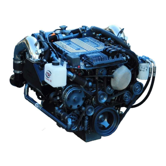
COMPONENT IDENTIFICATION Heat exchanger pressure cap Intercooler pressure cap sensor MEFI 7 ECM Exhaust Riser Flame arrestor Remote oil filter Exhaust manifold Supercharger drive belt Coolant transfer pipe 50 AMP circuit breaker Coolant overflow reservoir Alternator Water pump... - Page 13 COMPONENT IDENTIFICATION CONTINUED Thermostat housing Relay and Fuse box Heat exchanger Oil cooler Intercooler Pump Starter Customer Interface Connector The illustrations above show the general location of engine controls, engine components and their functions. These illustrations will help identify where these parts are located on the engine. Locations may vary from engine to engine.
-
Page 14: Parts And Service
They hope to see all of your maintenance and service needs are quickly and courteously completed. Feel free to contact KEM Equipment Inc./Kodiak Marine regarding your experiences with our service dealers, good or bad. -
Page 15: Pre Operational Inspection
PRE-OPERATIONAL INSPECTION WARNING: Remove the key from the ignition prior to any engine check or operation. Do not energize any engine prior to performing any of the following. Before operating your engine, you must perform a pre-operational inspection. 1. Open the engine hatch cover to let the compartment air out for at least ten minutes. 2. -
Page 16: Malfunction Indicator Light (Mil)
MALFUNCTION INDICATOR LIGHT Caution- Notice to Builder/Installer This engine requires use of a MIL. A MIL (Malfunction Indicator Lamp) must be installed with this engine to be in compliance with EPA and CARB regulations. There are two lights on the dash to indicate engine related problems. The operator is responsible to acknowledge any illuminated Check Engine or Check Gauges lights during the course of engine operation. - Page 17 is out of the normal range e.g., low oil pressure when the engine is at rated speed. If the engine should turn off for no apparent reason, check this lamp. This light will clear on its own if the fault clears and the ignition switch is turned off then back on.
-
Page 18: Starting The Engine
STARTING THE ENGINE Prior to starting the engine, the following must be performed. 1. Check engine oil level. 2. Check for fuel leaks. 3. Run bilge blower for a minimum of 10 minutes 4. Check coolant level 5. Check bilge for excess water before starting engine WARNING: The bilge can accumulate explosive fumes. -
Page 19: Starting Mode Fuel Injection
CAUTION: If the engine stalls or falters during starting, wait 3 to 4 seconds before re-engaging the starter. This will prevent possible damage to the starter or the engine. Do NOT operate the starter for periods longer than 5-8 seconds at a time. An interval of at least 1 minute should be observed between cranking periods to protect the starter from overheating. -
Page 20: Stopping The Engine
STOPPING THE ENGINE NORMAL CONDITIONS Let the engine idle for at least one minute prior to stopping the engine to reduce residual heat in engine components. Not doing this will not harm anything, but gives the engine a chance to reduce the temperature of many components. -
Page 21: General Maintenance
GENERAL MAINTENANCE WARNING: Extreme High Fuel Rail Pressure. The SIDI Fuel Injectors and fuel rail have extremely high fuel pressures. Do not attempt to remove or service these parts. This poses a potentially hazardous situation that if not avoided, could result in severe personal injury or death, damage to engine, and/or property. - Page 22 QUICK REFERENCE, GENERAL SPECIFICATIONS, AND MAINTENANCE SCHEDULE Use this Quick Reference and the Maintenance Schedule starting on page 23 to ensure that all of the maintenance items listed are checked and replaced at the recommended hours. LT4 ENGINE QUICK REFERNCE ENGINE COOLANT CAPACITY 5.125 US GALLONS OR 656 oz INTERCOOLER COOLANT CAPACITY...
-
Page 23: Maintenance Schedule
MAINTENANCE SCHEDULE SERVICE INTERVAL ENGINE CHECK POINTS EVERY 25 EVERY 50 EVERY 75 EVERY 100 EVERY 150 EVERY 200 EVERY 300 EVERY 400 DAILY HOURS HOURS HOURS HOURS HOURS HOURS HOURS HOURS GENERAL MAINTENANCE PRIOR TO ANY SERVICE OR MAINTENANCE ACTIVITY Inspect fuel system for leaks Inspect engine for fluid leaks Check engine oil... -
Page 24: Changing Engine Oil And Filter
CHANGING ENGINE OIL AND FILTER Under normal operating conditions, the engine oil and filter must be changed every 50 hours or every 12 months whichever occurs first. Use of premium quality oil and filters is recommended. The oil and filter should be changed more often if the engine is operating commercially or in severe conditions such as dirty areas or during cold weather. -
Page 25: Oil Filter
OIL FILTER NOTE: Ensure the old filter gasket is removed prior to installing the new filter. GM Powertrain based Kodiak Marine engines use an AC Delco (or equivalent) oil filter as original equipment. An equivalent oil filter must be used when servicing the engine (see Engine Quick Reference on page 22 for the recommended oil filter for your engine). -
Page 26: Cooling System
COOLING SYSTEM KEM Equipment and GM Powertrain recommend the use of DEX-COOL coolant in all GM engines. WARNING: Engine Damage may occur: All LT4 engines must be vacuum filled with coolant. If you need assistance or have questions, contact your local service dealer. Failure to vacuum fill this engine with the recommended coolant may void all warranty. -
Page 27: Engine Heat Exchanger
Plain water can be used in an emergency, but must be replaced with the specified mix of coolant as immediately to avoid freezing and other damage to the system. Do not let the engine run hot with only water acting as the primary coolant. A 50/50 mixture is recommended and will provide protection from freezing to -35F/-37C. -
Page 28: Fuel Injection System
FUEL INJECTION SYSTEM WARNING: Extreme High Fuel Rail Pressure. The SIDI Fuel Injectors and fuel rail have extremely high fuel pressure. Do not attempt to remove or service these parts. This poses a potentially hazardous situation that if not avoided, could result in severe personal injury or death, or damage to engine and or property. -
Page 29: Fuel Filter
The pressure regulator is preset at the factory. The fuel pressure must be between 65-67 psi before running the engine. Contact your service dealer or KEM Equipment if you have fuel pressure questions. FUEL TYPE The LT4 engine requires a minimum of 92 octane premium unleaded gasoline. -
Page 30: Ignition System
IGNITION SYSTEM WARNING: High voltage ignition system. Electrical shock hazard. WARNING: The bilge can accumulate explosive fumes. The bilge blower will evacuate the fumes. The bilge blower must be run for a minimum of 10 minutes prior to cranking the engine. Ignition system type: Kodiak LT4 engines have computer controlled ignition systems. -
Page 31: Engine Does Not Crank
The largest percentage of all malfunctioning equipment will be due to simple or small problems. Most operating troubles that might be encountered with a new or well-maintained unit will be of a minor nature. Consequently, if you experience any problems starting or operating your engine, look for a simple cause rather than failure of a major component. -
Page 32: Engine Cranks, But Only Intermittently
WARNING: The bilge can accumulate explosive fumes. The bilge blower will evacuate the fumes. The bilge blower must be run for a minimum of 10 minutes prior to cranking the engine. • Check battery cables – adjust any loose connections and clean any corrosion •... -
Page 33: Engine Runs Hot
WARNING: Extreme High Fuel Rail Pressure. The SIDI Fuel Injectors and fuel rail have extremely high fuel pressure. Do not attempt to remove or service these parts. This poses a potentially hazardous situation that if not avoided, could result in severe personal injury or death, damage to engine and or property. -
Page 34: Emissions
WARNING: The bilge can accumulate explosive fumes. The bilge blower will evacuate the fumes. The bilge blower must be run for a minimum of 10 minutes prior to cranking the engine. CAUTION: DO NOT add coolant or water to any engine that has become overheated until the engine cools. -
Page 35: Storage Or Lay-Up
This engine is certified for inboard use only in jet drive and stern drive vessels. Installation of this engine in outboard applications is a violation of the Clean Air Act. This engine and the installed system components are designed to meet the current CARB and EPA emissions requirements. -
Page 36: Winterization
WINTERIZATION To winterize the LT4, prepare the boat for long term storage and drain the raw water side or seawater side of the cooling system. It’s best to remove the end caps from the heat exchanger, oil cooler, and intercooler charge cooler to drain and remove debris. At a minimum, the charge cooler has a plug in the bottom near the rear of cooler for draining the raw water. - Page 37 3. Change engine oil and filter. 4. Check coolant levels - make sure fluids are at the proper levels. 5. Check for oil, coolant, and fuel leaks - correct any leaks prior to proceeding further. 6. Check battery charge and fluid level - inspect connections for corrosion, clean as necessary. 7.
-
Page 38: Warranties
Kodiak Marine dealer in your area. Contact your Kodiak Marine dealer directly for any required warranty repairs. If you have concerns with, or need further assistance with a warranty claim or a warranty repair, Contact KEM Equipment 503-692-501... - Page 39 Select emission control parts from model year 2009 and later inboard or stern drive engines are warranted for 3 years or 150 hours, whichever occurs first. If any emission-related part on your engine is defective under warranty, the part will be repaired or replaced by KEM Equipment, Inc. / Kodiak Marine.
-
Page 40: General Emissions Warranty
Health and Safety Code; and, (2) Free from defects in materials and workmanship that cause the failure of a warranted part to be identical in all material respects to that part as described in KEM Equipment Inc. / Kodiak Marine’s application for certification. - Page 41 (7) KEM Equipment, Inc. / Kodiak Marine is liable for damages to other engine components proximately caused by a failure under warranty of any warranted part.
- Page 42 The repair or replacement of any warranted part otherwise eligible for warranty coverage may be excluded from such warranty coverage if KEM Equipment, Inc. / Kodiak Marine demonstrates that the engine has been abused, neglected, or improperly maintained, and that such abuse, neglect, or improper maintenance was the direct cause of the need for repair or replacement of the part.
- Page 43 K O D I A K M A R I N E E N G I N E W A R R A N T Y 1 YEAR LIMITED WARRANTY EFFECTIVE JANUARY 1 , 2019 Length of Warranty (from date of original retail purchase) Products Covered Non-commercial Commercial/Rental...
-
Page 44: Kodiak Marine Warranty
KODIAK MARINE WARRANTY EXCLUSIONS THIS WARRANTY DOES NOT EXTEND TO THE FOLLOWING: CONDITIONS CAUSED BY LACK OF ROUTINE MAINTENANCE (AS OUTLINED IN THE OPERATOR’S MANUAL) CONDITIONS CAUSED BY THE USE OF A PROPELLAR, IMPELLER, OR IMPELLERS THAT DO NOT ALLOW THE INBOARD ENGINE TO RUN IN ITS RECOMMENDED FULL THROTTLE RPM RANGE ... - Page 45 In the event that a warranty claim is required outside of the continental United States, with the exception of Alaska and Hawaii, there may be additional charges to the engine owner. KEM Equipment, Inc./Kodiak Marine will not warranty any engine or jet sold outside the continental United States, with the exception of Alaska and Hawaii, unless competent and trained personal are available to provide service to the engine or jet.
-
Page 46: On Board Diagnostic (Obd) System Check
ON BOARD DIAGNOSTIC (OBD) SYSTEM CHECK WARNING: Fire, Shock, and Burn Danger: When performing any diagnostics or service work use caution. This system has extreme fuel pressures and a high voltage ignition. CAUTION: Electronic controls contain static-sensitive parts. Observe the following precautions to prevent damage to these parts. -
Page 47: Diagnostic Error Codes
Attempt to start the engine: Verify that the engine cranks. -If the engine does not crank, refer to SPN 66001 or SPN 66002 (if equipped). -Attempt to start the engine. Verify the engine starts and idles. Important: Do not clear any SPNs unless instructed to do so by a diagnostic procedure. -Use the appropriate scan tool selections to obtain SPNs from each of the vehicle modules. - Page 48 SPN 105 SPN Descriptors SPN 105 FMI 3: Manifold Air Temperature (MAT) Sensor Circuit Voltage Above Normal or Shorted High SPN 105 FMI 4: Manifold Air Temperature (MAT) Sensor Circuit Voltage Below Normal or Shorted Low SPN 106 SPN Descriptors SPN 106 FMI 0: Manifold Absolute Pressure (MAP) Sensor Circuit Voltage Data Valid But Above Normal SPN 106 FMI 1: Manifold Absolute Pressure (MAP) Sensor Circuit Voltage Data Valid But Below Normal SPN 106 FMI 3: Manifold Absolute Pressure (MAP) Sensor Circuit Voltage Above Normal or Shorted High...
- Page 49 SPN 651, 652, 653, 654, 655, 656, 657, or 658 SPN Descriptors SPN 651 FMI 3: Fuel Injector 1 Voltage Above Normal or Shorted High SPN 651 FMI 5: Fuel Injector 1 Current Below Normal or Open Circuit SPN 652 FMI 3: Fuel Injector 2 Voltage Above Normal or Shorted High SPN 652 FMI 5: Fuel Injector 2 Current Below Normal or Open Circuit SPN 653 FMI 3: Fuel Injector 3 Voltage Above Normal or Shorted High SPN 653 FMI 5: Fuel Injector 3 Current Below Normal or Open Circuit...
- Page 50 SPN 65560 SPN Descriptors SPN 65560 FMI 9: CAN Bus Governor Command Abnormal Update Rate SPN 65561, 65562, 65563, or 65564 SPN Descriptors SPN 65561 FMI 0: Oxygen Sensor Bank A Sensor 1 Data Valid But Above Normal SPN 65561 FMI 1: Oxygen Sensor Bank A Sensor 1 Data Valid But Below Normal SPN 65561 FMI 3: Oxygen Sensor Bank A Sensor 1 Voltage Above Normal or Shorted High SPN 65561 FMI 4: Oxygen Sensor Bank A Sensor 1 Voltage Below Normal or Shorted Low SPN 65561 FMI 5: Oxygen Sensor Bank A Sensor 1 Current Below Normal or Open Circuit...
- Page 51 SPN 65590, 65591, 65592, 65593, 65594, 65595, 65596, 65597, 65598, or 65599 SPN Descriptors SPN 65590 FMI 7: Misfire Mechanical System Not Responding or Out of Adjustment SPN 65591 FMI 7: Misfire Cylinder 1 Mechanical System Not Responding or Out of Adjustment SPN 65592 FMI 7: Misfire Cylinder 2 Mechanical System Not Responding or Out of Adjustment SPN 65593 FMI 7: Misfire Cylinder 3 Mechanical System Not Responding or Out of Adjustment SPN 65594 FMI 7: Misfire Cylinder 4 Mechanical System Not Responding or Out of Adjustment...
- Page 52 SPN 65672 FMI 3: Catalytic Converter B Temperature Sensor Voltage Above Normal or Shorted High SPN 65672 FMI 4: Catalytic Converter B Temperature Sensor Voltage Below Normal or Shorted Low SPN 65673 or 65674 SPN Descriptors SPN 65673 FMI 15: Catalytic Converter A Temperature Sensor Data Valid But Above Normal Range-Least Severe Level SPN 65674 FMI 15: Catalytic Converter B Temperature Sensor Data Valid But Above Normal Range-Least Severe Level...
- Page 53 SPN 66002 SPN Descriptor SPN 66002 FMI 4: Starter Relay High Side Driver Voltage Below Normal or Shorted Low SPN 66002 FMI 5: Starter Relay High Side Driver Current Below Normal or Open Circuit SPN 66003 SPN Descriptor SPN 66003 FMI 3: Malfunction Indicator Lamp (MIL) Driver Voltage Above Normal or Shorted High SPN 66003 FMI 5: Malfunction Indicator Lamp (MIL) Driver Current Below Normal or Open Circuit SPN 66004 SPN Descriptor...
- Page 54 SPN 66013 or 66014 SPN Descriptor SPN 66013 FMI 3: Powertrain Relay Voltage Above Normal or Shorted High SPN 66013 FMI 5: Powertrain Relay Current Below Normal or Open Circuit SPN 66014 FMI 4: Powertrain Relay Contact Voltage Below Normal or Shorted Low SPN 66017 SPN Descriptors SPN 66017 FMI 4: Fuel Pump Relay 1 Voltage Below Normal or Shorted Low...
- Page 55 SPN 66040-66043 SPN Descriptor SPN 66040 FMI 3: OEM Output Driver 1 Voltage Above Normal or Shorted High SPN 66040 FMI 5: OEM Output Driver 1 Current Below Normal or Open Circuit SPN 66041 FMI 3: OEM Output Driver 2 Voltage Above Normal or Shorted High SPN 66041 FMI 5: OEM Output Driver 2 Current Below Normal or Open Circuit SPN 66042 FMI 3: OEM Output Driver 3 Voltage Above Normal or Shorted High SPN 66042 FMI 5: OEM Output Driver 3 Current Below Normal or Open Circuit...
-
Page 56: Marine Service Dealer Locations
Marine Service Dealers United States Alaska Michigan Anchorage Marne Boat Works of Alaska (907)344-2628 Professional Marine (907)562-2471 Camp & Cruise (616)677-1274 Cordova Montana Cordova Outboard (907)424-3220 Fairbanks Laurel Mt Alaska Marine & Repair (907)488-8887 American Jet Repair (406)780-1547 Wasilla Alaska Frontier Fab (907)357-9323 Oregon Bend... - Page 57 Washington Canada Chinook Chinook Marine Repair (360)777-8361 British Columbia Clarkston Chilliwack Pacific Powertrain (509)751-1800 Cascade Marine (800)663-2269 Wet Ever (208)790-3222 Venture Riverboats (604)792-3662 Issaquah Mission I-90 Marine Center (425)392-2748 Besse Marine Service (604)835-4176 Washougal Riverside Marina (360)835-8553 Alberta Woodinville Red Deer Doug's Boats (800)215-3684 Outlaw Marine...
-
Page 58: Notices To Service Dealers And Boat Builders
Failure to fill the engine o r i n t e r c o o l e r properly with a Coolant Air Evacuation kit may void warranty. Snap On Model #SVTSRAD262A is an easy to use air evacuation kit with easy to follow instructions included. It can be purchased from your local Kodiak Marine Dealer or order direct from KEM Equipment. - Page 59 OEM NOTICE TO ALL BOAT BUILDERS AND RIGGERS KEM EQUIPMENT IS ISSUING THIS NOTICE EFFECTIVE 10/30/2020 LT4 FUEL PUMP SYSTEM ASSEMBLY IN FROM TANK OUT TO ENGINE 100 MICRON 10 MICRON FUEL PUMP Note: Everything shown must be mounted as low as possible Plumbing: The fuel supply pick-up tube, fuel lines, and fittings shall be no smaller than ½”...
- Page 60 90° fittings. Setting the fuel pressure: The fuel pressure is set at the factory and cannot be adjusted. If you suspect a problem that is fuel pressure related, contact KEM Equipment, Inc. / Kodiak Marine service department at (503)692-5012.
- Page 61 OEM NOTICE TO ALL BOAT BUILDERS AND RIGGERS KEM EQUIPMENT IS ISSUING THIS NOTICE EFFECTIVE IMMEDIATELY 6/24/14 TO MEET EPA and CARB REQUIREMENTS: ALL KODIAK CERTIFIED MARINE ENGINES SOLD AFTER JANUARY 2007 MUST HAVE A CHECK ENGINE AND CHECK GAUGES LAMP.
- Page 62 OEM NOTICE TO ALL BOAT BUILDERS AND RIGGERS KEM EQUIPMENT IS ISSUING THIS NOTICE HIGH PERFORMANCE LT4 INSTALLATION REQUIREMENTS: Low Restriction Exhaust: For maximum power and efficiency, a low restriction exhaust should be fitted. Anything such as baffled through holes, mufflers, or turndowns combine to increase restriction and back pressure (measured in psi).
- Page 63 Appendix A KM 11255 Engine Wiring Schematic Appendix B KM 10754 Customer Interface Connector Pinout...
- Page 64 LT4 MARINE OPERATOR’S MANUAL PART # KM 11338...
- Page 65 RD 10 AWG 50A Circuit Breaker RD 10 AWG RD 10 AWG RD 10 AWG RD 10 AWG RD 18 AWG RD 12 AWG RD 12 AWG RD 10 AWG Cylinder Firing Order 1 8 7 2 6 5 4 3 10 AWG Fuel pump Coolant pump...
- Page 66 Description Position Wire Description Position Description Emergency Engine Stop MCI-A MCI-A Not Used Black 12 Power Ground (12-) MCI_B MCI_B 12- Power Ground Gray 16 Tachometer MCI-C MCI-C Not Used Red 12 Fused 12 Volt Power to Ignition Switch MCI-D MCI-D 12+ Fused to Ignition and Dash Green/Black...
Need help?
Do you have a question about the KODIAK MARINE LT4 SUPERCHARGED and is the answer not in the manual?
Questions and answers