
Related Manuals for Goldwing RC MX2 50CC V4


Summary of Contents for Goldwing RC MX2 50CC V4
- Page 1 GoldWing RC MX2 50CC V4 Giant Scale Aerobatic Aircraft All contents copyright 2014, GoldWing RC Version 2.0, Feb 2014...
-
Page 2: Specifications
Thank you for purchasing the new Goldwing RC giant scale aerobatic aircraft. This manual covers the MX2 50CC V4 aircraft. The MX2 is designed for the popular 50-70cc engines and weighs approximately 7.5 kg to 8.1 kg. Perfect for IMAC or Freestyle flying, this new giant offers everything you want in a giant scale aerobat including great looks! Covered in genuine Ultracote, this ARF comes with premium hardware, carbon fiber landing gear,, Larger diameter carbon fiber wing tube, stainless steel Axle kits,carbon fiber horns and... -
Page 3: Included Features
Goldwing RC WARRANTY AND RETURN POLICY GoldWing RC guarantees this product to be free from defects in both material and workmanship at the date of purchase. This does not cover any parts damaged by use, misuse or modification. In no case shall liability exceed the original cost of this kit. - Page 4 Larger aileron and elevator design. Up to 60 degrees of throw on all control surfaces for excellent 3D aerobatic flying High quality ball link assemblies All contents copyright 2014, GoldWing RC Version 2.0, Feb 2014...
- Page 5 Aluminium hub rubber wheels Improved axles (the material of the axle is now stainless steel ) Servo lead safety clips All contents copyright 2014, GoldWing RC Version 2.0, Feb 2014...
- Page 6 High performance cap head bolts Flat nylon hinges for inproved flying strength Honeycomb board carton packing for safer transportation All contents copyright 2014, GoldWing RC Version 2.0, Feb 2014...
- Page 7 Pre-hinged control surfaces Pre-assembled and mounted gas tank Installed servo wire guide tube All contents copyright 2014, GoldWing RC Version 2.0, Feb 2014...
- Page 8 Extra covering provided for small repairs, genuine Ultracote / Oracover Removable rudder Side force generators included All contents copyright 2014, GoldWing RC Version 2.0, Feb 2014...
- Page 9 CNC anodized aluminum canopy bolts Full length tuned pipe design inside the fuselage Carbon Fiber accessories version: Extra strength carbon fiber control horns All contents copyright 2014, GoldWing RC Version 2.0, Feb 2014...
- Page 10 One piece air foiled carbon fiber landing gear Carbon fiber tail wheel assembly with CNC machined metal parts, including the aluminium tail wheel hub. All contents copyright 2014, GoldWing RC Version 2.0, Feb 2014...
- Page 11 Increased diameter carbon fiber wing tube over previous versions Carbon fiber stab tube All contents copyright 2014, GoldWing RC Version 2.0, Feb 2014...
- Page 12 Scheme A White/black/green All contents copyright 2014, GoldWing RC Version 2.0, Feb 2014...
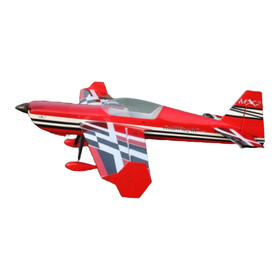
- Page 13 Scheme C Red/white/black All contents copyright 2014, GoldWing RC Version 2.0, Feb 2014...
- Page 14 3. Some modelers prefer to seal the hinge gaps using strips of appropriate covering or clear trim tape. We have found this to be helpful with models intended for higher speed flight or models with unusually large All contents copyright 2014, GoldWing RC Version 2.0, Feb 2014...
- Page 15 Carbon Fiber control Horns (Bag No. KA06CA) : 8 single horns for ailerons and elevator. 2 dual horns for rudder. Sand the area of the horn that will be glued to help adhesion. All contents copyright 2014, GoldWing RC Version 2.0, Feb 2014...
- Page 16 Ball link assembly (Bag No. KAG00131): 8 for ailerons and elevators. Alu long arm kits (Bag No. KA05CC): 4 single arms for ailerons and elevators. 1 dual arm for the rudder. All contents copyright 2014, GoldWing RC Version 2.0, Feb 2014...
- Page 17 3.5” Alu main wheels:2pcs(Bag No. KAG0159) New stainless steel Axle kits (Bag No. KA05CH) Carbon fibre tail wheel assembly with CNC machined metal parts, including the aluminium tail wheel hub. (Bag No. KAGC104) All contents copyright 2014, GoldWing RC Version 2.0, Feb 2014...
- Page 18 4mm ALU canopy bolts (Bag No.KAG0043) Extra covering provided for small repairs Wrench set (Bag No. KA05CE) Side force generators (4 x 3x20mm hex bolts & 4 x washers & 2 balsa sheet) All contents copyright 2014, GoldWing RC Version 2.0, Feb 2014...
- Page 19 Bolts for landing gear: 4(4x20mm) hex bolts & 4 washers & 4(M4) stainless steel self-locking nuts Bolts & washers for cowl: 4(3x16mm) Hexagon bolts and 4 washers Spares bag(Two spare aluminum hand-twist bolts \Two spare wing bolts\One spare tail wheel spring) All contents copyright 2014, GoldWing RC Version 2.0, Feb 2014...
-
Page 20: Rudder Assembly
Install the ball links, bolts and nuts into the holes to help assure alignment of both control horns while the glue cures. Set aside until cured. NOTE: There are pictures of different planes in this manual; however, this plane’s rudder is assembled the same way. All contents copyright 2014, GoldWing RC Version 2.0, Feb 2014... - Page 21 CA into the holes to strengthen the wood. You will need 3 inch arms on the servo. Set up your radio accordingly and center the rudder servo. 7.Aluminum dual servo arm are include in the kit, enlarge the control holes with 3mm drill bit. All contents copyright 2014, GoldWing RC Version 2.0, Feb 2014...
- Page 22 Hint: Once you have established the position of the threaded coupler on the cable, you can remove the ball link from the rudder horn to give you more working slack in the fuselage. Re-install the ball link prior to setting the other cable. All contents copyright 2014, GoldWing RC Version 2.0, Feb 2014...
- Page 23 13. Use 3x165mm push rod between the servo and the rudder horn. Then use the wrench to adjust the pushrod to the appropriate length. All contents copyright 2014, GoldWing RC Version 2.0, Feb 2014...
-
Page 24: Landing Gear Assembly
2. Bolt the main gear to the bottom of the fuselage using the supplied bolts. Place the nuts in through the can tunnel opening with appropriate size spanner. Remember the gear will rake forward. All contents copyright 2014, GoldWing RC Version 2.0, Feb 2014... - Page 25 Slide the wheel onto the axle and install a second wheel collar also using thread-lock on the set screw. For greater strength, filing a flat where the grub screw mounts will stop the collet being able to be turned. All contents copyright 2014, GoldWing RC Version 2.0, Feb 2014...
- Page 26 6. Use your finger to find the three holes at the bottom of the fuselage. Using a knife clear the holes and fix the tailwheel in place. Use loctite on the bolts. Then install the spring, using the self-tapping screw to attach the other end of the spring onto the rudder. All contents copyright 2014, GoldWing RC Version 2.0, Feb 2014...
- Page 27 8. The following is a picture of correctly installed tail wheel assembly. NOTE: One spare tail wheel spring is included in the spare hardware pack. All contents copyright 2014, GoldWing RC Version 2.0, Feb 2014...
-
Page 28: Wings Assembly
2. Locate the slots for the aileron control horn and remove the covering with a sharp knife. Place the horns into position and the cover over the top to work out the area needing to be removed. All contents copyright 2014, GoldWing RC Version 2.0, Feb 2014... - Page 29 4. Using 30 minute epoxy glue the horn and plate into the aileron. REPEAT FOR THE OTHER SIDE 5. A string is pre-placed in the wing to facilitate the installation of aileron servo wire. All contents copyright 2014, GoldWing RC Version 2.0, Feb 2014...
- Page 30 7. Tie up servo extension with the string, and then pull it through the wing. 8. Screw holes for servo mounting are pre-drilled by laser in factory, install servo with 4 self threading screws. All contents copyright 2014, GoldWing RC Version 2.0, Feb 2014...
- Page 31 9. Locate the included aluminum long servo arm, enlarge control holes with 3mm drill bit 10. Using the pushrods connect the servo arm to the horn. Remember that on the pushrod one end is reverse threaded. All contents copyright 2014, GoldWing RC Version 2.0, Feb 2014...
-
Page 32: Elevator Assembly
1. Push rod linkage set for elevator. 3mmx60mm Pushrods for elevator. 2. Find the slots for the control arms in the elevators and remove the covering where the horns are inserted and the area for the plate. All contents copyright 2014, GoldWing RC Version 2.0, Feb 2014... - Page 33 4. Using plenty of 30 minute epoxy fit the horn and plate into place. Use a ball joint and bolt to hold the horn in place while drying. REPEAT FOR THE OTHER SIDE 5. Place long arms onto the servo’s you are planning to use for the elevators. All contents copyright 2014, GoldWing RC Version 2.0, Feb 2014...
- Page 34 8. Fit the pushrod in place remembering one end is reverse threaded. Set it so the arm is centered and the elevator is flat. Choose the holes depending on how much deflection you require. All contents copyright 2014, GoldWing RC Version 2.0, Feb 2014...
- Page 35 2. Fit the Cowl and measure the distance from the engine bulkhead to the front of the cowl, add approx 2- 3mm for the spinner back plate and this is the length that your engine should be set Using the correct length All contents copyright 2014, GoldWing RC Version 2.0, Feb 2014...
- Page 36 50cc-70cc engines. Mount your throttle servo and complete your linkage setup. A hole will need to be drilled on the firewall to allow the pushrod to connect to the throttle arm on the carb. All contents copyright 2014, GoldWing RC Version 2.0, Feb 2014...
- Page 37 If a tuned pipe is going to be used the end of the can tunnel can be removed. The tunnel can be closed off to accept canisters of all sizes, or stock mufflers. Follow the manufacturer’s instructions for your exhaust All contents copyright 2014, GoldWing RC Version 2.0, Feb 2014...
- Page 38 Pitts Muffler Canister Fitting Tuned Pipe Mounting All contents copyright 2014, GoldWing RC Version 2.0, Feb 2014...
-
Page 39: Cowling Installation
Remove the engine and refit the cowl. Then fold over the card to show where the cylinder head would be as below. 2. Mark onto the cowl the area to remove, and remove with a dremel. All contents copyright 2014, GoldWing RC Version 2.0, Feb 2014... - Page 40 3.The cowl is secured with four 3 x 16mm bolts and washers. Apply nutlock onto the bolts as the vibration from the gas engine will shake them come loose. All contents copyright 2014, GoldWing RC Version 2.0, Feb 2014...
- Page 41 Labels are provided for aligning the drill holes for the cowl. Stick then on without the cowl, mark the hole. Fit the cowl then press back down. The hole will then show the area to drill. Sere below. All contents copyright 2014, GoldWing RC Version 2.0, Feb 2014...
- Page 42 To perform properly without being too pitch sensitive, you must not go too aft on the CG. GoldWing RC recommends an initial CG setting of 136-158mm (5.4-6.2inches) behind the leading edge of the wing at the root. More experienced pilots may want to set the CG further aft for more 3D capability.
- Page 43 2. Installation of the rudder The rudder is removable for convenience in transportation, it is connected to fuselage by inserting a 1.8 mm steel rod through the hinge line. All contents copyright 2014, GoldWing RC Version 2.0, Feb 2014...
- Page 44 Hook up the tail wheel spring. 3.Installation of Elevators Connect servo extension wire, secure with safe clips. Attach elevators with 3x12mm Hex-head bolts and washers. Check these after every flight. All contents copyright 2014, GoldWing RC Version 2.0, Feb 2014...
- Page 45 5.Side force generators assembly. Cut the wing film needed to be install the SFG. Fixed the SFG Use M3X20 cap head bolts and washers and balsa sheet. All contents copyright 2014, GoldWing RC Version 2.0, Feb 2014...
- Page 46 7. Position the canopy in place and tighten ALU canopy bolts. Be sure to use the supplied rubber washers under the screw heads. NOTE: Two spare aluminum hand-twist canopy bolts is included in the spare hardware pack. All contents copyright 2014, GoldWing RC Version 2.0, Feb 2014...
- Page 47 * KUZA Heavy duty 7075 aluminum Servo Arm For Futaba servo(25T): 47mm/1.75in Single No. KAG0S7F 100mm/4in Dual No. KAG0D723F For Hitec servo(24T): 47mm/1.75in Single No. KAG0S7H 100mm/4in Dual No. KAG0D73H All contents copyright 2014, GoldWing RC Version 2.0, Feb 2014...
- Page 48 For JR servo(23T): 47mm/1.75in Single No. KAG0S73J 100mm/4in Dual No. KAG0D73J * 3.5in C.F Spinner No. KAG0135 * Wingbags for 50CC No. KAG0094 All contents copyright 2014, GoldWing RC Version 2.0, Feb 2014...
- Page 49 All contents copyright 2014, GoldWing RC Version 2.0, Feb 2014...
Need help?
Do you have a question about the MX2 50CC V4 and is the answer not in the manual?
Questions and answers