
Related Manuals for ABB Zenith ZT30


Summary of Contents for ABB Zenith ZT30
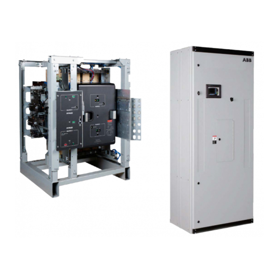
- Page 1 — O P E R A T I O N A N D M A I N T E N A N C E M A N U A L Zenith ZT30 and ZB30 Short-time rated ATS and Bypass Isolation ATS...
-
Page 2: Table Of Contents
Bypass ATS Sequence of Operations – Racking Operations ..22 Sequence of Operation – Automatic mode - Isolation ATS ..25 Zenith Automatic Transfer Switch new.abb.com/low-voltage... - Page 3 Table T7-2: Replacement Parts List ......59 Zenith Automatic Transfer Switch | new.abb.com/low-voltage...
-
Page 4: Section 1: General Information
ABB Zenith Controls assumes no obligation of notice to holders of this document with respect to changes subsequently made. ABB Zenith Controls makes no representation or warranty,... - Page 5 6. Check to be sure that all covers and barriers are properly installed and fastened. 7. If any damage is found or suspected, le a claim as soon as possible with the carrier & notify the nearest ABB Zenith representative or call 1-800-637-1738 option 3. Zenith Automatic Transfer Switch |...
-
Page 6: Section 3: Lifting, Mounting And Installation Ats & Bypass
Section 3: Lifting, Mounting and Installation Unpacking the ATS The safe operation of your switch at all times is ABB Zenith focus. It must be recognized that hazardous voltages and currents can exist during normal operation and any maintenance on the transfer switch must be performed utilizing appropriate safety measures. -
Page 7: Lifting And Mounting Guidance
Lifting Guidelines for Enclosed ATS/Bypass Isolation ATS WARNING 1. ABB Zenith ATS are mounted onto a wooden pallet using the Due to hazardous voltages and currents, ABB recommends bolts & nuts. Please remove the bolts & nuts prior to lifting that an ABB Certified technician or a qualified electrician 2. - Page 8 Figure S3-4 : Open style ATS ATS & Bypass Isolation ATS Mounting: 1. Anchoring provisions are provided on all the ABB Zenith ATS & Bypass Isolation enclosures. 2. For open style ATS & Bypass Isolation ATS mounting please refer to the dimensional drawings shipped available on ABB Critical Power Website http://www.geindustrial.com/...
-
Page 9: Tools Needed For Installation And Maintenance
PS-8419 500 kcmil Compression lug PS-8467 600 kcmil Compression lug PS-8420 750 kcmil Table T3-2: Listing of mechanical and compression lug AMPERAGE DRAWING NUMBER 1000A-2000A 2600A-3000A Mechanical lug O-4106 O-4106 Compression lug O-4107 O-4107 Zenith Automatic Transfer Switch | new.abb.com/low-voltage... -
Page 10: Section 4: Standalone Ats Operations
Access Panel ATS Mechanical Fiscia Indicator Panel Options Panel (on request) Figure S4-1: Front view of ATS (Standalone) in an enclosure (MX350 variant). Figure S4-2: Front view of ATS (Standalone) in an enclosure (MX350 variant). Zenith Automatic Transfer Switch new.abb.com/low-voltage... - Page 11 Assembly Assembly S2 Limit Switch Assembly S2 Motor Assembly S1 Open and Close Solenoid Assembly Figure S4-5: View of ATS Intra-Panel Interlocks System. Figure S4-6: Alternate view of Standalone ATS (3-pole, shown without fascia). Zenith Automatic Transfer Switch | new.abb.com/low-voltage...
-
Page 12: Sequence Of Operations - Manual Mode
Further clockwise rotation of the Charging Handle could damage the equipment. Manual Open Button Figure S4-7: Showing mechanism status & contact position indication for source 1 Figure S4-8: Showing manual open button Zenith Automatic Transfer Switch new.abb.com/low-voltage... -
Page 13: Sequence Of Operations - Automatic Mode
A manual pushbutton BYPASS is provided to bypass the “W” time delay if desired. After the (W) time delay, the MX controller initiates a transfer signal through the Relay Driver Module to operate the main transfer Zenith Automatic Transfer Switch | new.abb.com/low-voltage... - Page 14 Relay Driver Module to operate the main transfer operator. The load is now transferred to Source 2 line. The transfer switch is mechanically locked. SN limit switch awaits the next operation to Source 1. Zenith Automatic Transfer Switch new.abb.com/low-voltage...
- Page 15 ATS Open Time S2 Stop Delay Start Stable to S2 Stable to S1 Source 1 Fails Transfer to Source 2 Transfer to Source 1 Engine Source 1 Returns Cooldown S4-11 Showing timer set menu Zenith Automatic Transfer Switch | new.abb.com/low-voltage...
- Page 16 • Requires an Isochronous Governor with an operating frequency of 60+/- 0.2 Hz. • Requires a Shunt Trip Breaker on the Generator set with a ABB Zenith Closed Transition Transfer Switches are designed response time not exceeding 50 milliseconds. to Transfer the Load between two available sources without interrupting power to the Load (Make-Before- Break).
- Page 17 *Permissible operations are given for illustrative purposes only. Never attempt to manually close contacts with opposite source contacts closed OPERATIONS NUMBER OF CRANKS REQUIRED Main spring charge Approx. 13 Table T4-3: Stored Energy Mechanism Sequences of Operation Zenith Automatic Transfer Switch | new.abb.com/low-voltage...
-
Page 18: Section 5: Bypass Isolation Ats Operations
Bypass Switch MX Controller Annunciation Lights ATS Contact Reset Control Switch E2231B Options Panel Access Panel for Bypass Operations Figure S5-1: Front view of Bypass Isolation ATS in an enclosure (MX350 controller shown). Zenith Automatic Transfer Switch new.abb.com/low-voltage... - Page 19 Racking Position Indicator Access Point (Source 2) Bypass Source 2 Close Button Source 2 Charge Bypass Source 2 LED Indicator Position Indicator Figure S5-2: View of Bypass Access Panel with various indicators and push buttons. Zenith Automatic Transfer Switch | new.abb.com/low-voltage...
- Page 20 In Bypass Isolation ATS same charging handle needs to use for racking the Isolation ATS. Charging Handle Charging/ Racking Handle Figure S5-5: Location of Charging Handle on the Standalone ATS product. Figure S5-6: Location of Charging Handle on the Isolation Bypass ATS product. Zenith Automatic Transfer Switch | new.abb.com/low-voltage...
-
Page 21: Sequence Of Operations - Manual Mode - Isolation
For instance, S1 “Ready” The Isolation ATS will NOT be operational electrically. indicates that the S1 mechanism spring is charged. Refer to table T4-1 for all possible combination of status indication. Zenith Automatic Transfer Switch | new.abb.com/low-voltage... -
Page 22: Bypass Ats Sequence Of Operations - Racking Operations
15. To rack out to the ISOLATE position, continue to rotate the the Bypass ATS to the intended power source. Charging Handle counter-clockwise until the “ISOLATE” Status Annunciation Light is illuminated. 16. To Remove ATS: Refer to the “Removal of the Isolation ATS” section. Zenith Automatic Transfer Switch new.abb.com/low-voltage... - Page 23 Control Switch in Inhibit will prevent ATS electrical operation. DO NOT use excessive force on the Charging Handle. When ATS is in Test or Isolate, Bypass Switch is a manual transfer switch to either available source (indicated on light panel). Zenith Automatic Transfer Switch | new.abb.com/low-voltage...
- Page 24 Figure S5-10: Application of lifting provisions onto the Isolation ATS prior to removal. Figure S5-11: Removal of the Isolation ATS out from the Bypass system. Figure S5-8: Operator pulling Isolation ATS out to be serviced. Figure S5-9: Position of the Isolation ATS prior to removal. Zenith Automatic Transfer Switch new.abb.com/low-voltage...
-
Page 25: Sequence Of Operation - Automatic Mode - Isolation Ats
A manual pushbutton BYPASS is provided to (U) timing cycle, the controller sends an Engine stop signal. bypass the “U” time delay if desired. Upon completion of the (U) timing cycle, the controller sends an Engine stop signal. Zenith Automatic Transfer Switch | new.abb.com/low-voltage... - Page 26 Sources would be parallel, under these conditions, is less than 500 milliseconds. Before operating ABB Zenith Closed Transition Transfer Switches are designed the Closed Transition Transfer Switch, the condition must to Transfer the Load between two available sources be corrected and the Shunt Trip reset.
- Page 27 Customer Use I: Engine Start C: Electrical Terminals Panel Input: H: Customer I/O CPS Box F: Engine Start Relay E: Relay Driver Module D: Maintenance Switch Figure S5-13: Front view of MX250 Electrical Panel Zenith Automatic Transfer Switch | new.abb.com/low-voltage...
- Page 28 NOTE: The controller will illuminate Source 1 Available LED if proper systems have been fully commissioned. voltage is sensed. 5. Verify the phase to phase voltages at Source 1 line terminals. 6. Close Source 2 source circuit breaker. Zenith Automatic Transfer Switch new.abb.com/low-voltage...
- Page 29 NOTE: The engine generator will continue to run for the duration of Source 2 Stop Delay Timer. 10. Place the Control Switch to Inhibit. 11. Complete the visual inspection of the transfer switch. 12. Close the enclosure. 13. Lock the enclosure. Zenith Automatic Transfer Switch | new.abb.com/low-voltage...
- Page 30 Source 1. Adjust voltage to control level for controller input via the SET menu. Range is 90% to 100% in 1% timer will begin timing to transfer to Source 1. Zenith Automatic Transfer Switch new.abb.com/low-voltage...
- Page 31 Over Voltage “Fail” Factory Default: 110% This adjustment determines the maximum acceptable Over Voltage. Adjust via the SET menu. Range is 105% to 110% timer will be bypassed to expedite the transfer to Source 1. Zenith Automatic Transfer Switch | new.abb.com/low-voltage...
- Page 32 5 and 60 minutes in 1 minute increments. Can be Adds Pre-wiring for Enervista Viewpoint Monitoring of M90. Accessory and ATS Status is 20minutes. When exerciser is impending, (*E*) appears in using Modbus RS485 Serial Communications Zenith Automatic Transfer Switch new.abb.com/low-voltage...
- Page 33 Generator to 60Hertz could cause lengthy transfer delay. can be given to switch to the dead Source 1 or R50 Feature can be turned ON or OFF via CFG Mid position, on Delayed Transition ATS Zenith Automatic Transfer Switch | new.abb.com/low-voltage...
- Page 34 (S2) Source 2 Stop Delay Timer, allows Engine to run unloaded after switch retransfer to Source 1. Adjustable 0-60 minutes in 1 second increments. Standard setting is Zenith Automatic Transfer Switch new.abb.com/low-voltage...
- Page 35 19. Cursor is indicated as a line under character to be changed Change values with up and down keys. 20. Press SAVE when complete. 21. Press MORE repeatedly until SET USER SETUP then press BACK then ESC to the S1 OK screen. Zenith Automatic Transfer Switch | new.abb.com/low-voltage...
- Page 36 Factory con gured for a Load Exerciser. How to Bypass the Next Exercise Event and Keep the Rest of Scheduled Events Unchanged 1. Press Test 2. Press MORE Press BYPASS EXER To re-institute the next exercise event back, press CANCL BPASS Zenith Automatic Transfer Switch new.abb.com/low-voltage...
- Page 37 ESC to the S1 OK screen. How to Bypass (Cancel) an Exercise During an Exercise Cycle 1. Press BPASS 2. Allow the controller to complete the Engine cool down cycle. Exercise. or allow the controller to complete retransfer to Zenith Automatic Transfer Switch | new.abb.com/low-voltage...
- Page 38 Standard Accessory included in the group package. Optional Accessory not included but can be added to the group package Optional Accessory. Can not be used with accesory having the same symbol. * Delayed Transition Units Only Zenith Automatic Transfer Switch new.abb.com/low-voltage...
- Page 39 Figure S6-4: Graphical interface of the Entelli Switch 250. Zenith Automatic Transfer Switch | new.abb.com/low-voltage...
- Page 40 Time, Date & Month for 14-DAY, Up and Down 28-DAY and 365-DAY Exerciser Use to change values (24 Hour System) To save value and to move cursor to next or to exit screen Figure S6-5: Exerciser programming window – MX250 Zenith Automatic Transfer Switch new.abb.com/low-voltage...
- Page 41 PHASE IMBALANCE (VI) ON/OFF (24) PHASE ROTATION MATCH (R16) ON/OFF (23) LOAD DISCONNECT TD (UMD) ( TRANSFER ALARM (CTAP) ON/OFF (21) NETWORK (ZNET) ON/OFF (24) *Optional Accessories Figure S6-6: Options selection via the CFG menu Zenith Automatic Transfer Switch | new.abb.com/low-voltage...
- Page 42 S2 STOP DELAY (U) (24) FAIL 5%, RESTORE 3% (24) CALIBRATE S1 (21) SET PHASE IMBALANCE (VI) TIME DELAY 30 seconds (24) CALIBRATE S2 (21) *Optional Accessories Figure S6-7: Options selection via the SET menu Zenith Automatic Transfer Switch new.abb.com/low-voltage...
- Page 43 View System Data Enter six digit access code (The factory assigned six-digit access code is located on the back of the controller) Figure S6-8: System Data View on the MX250 Zenith Automatic Transfer Switch | new.abb.com/low-voltage...
- Page 44 9. Verify that all cable lug connections are tightened in accordance to the Fascia label. 10. Remove surface oxides from cables by cleaning with a wire brush. 11. Make sure that all covers and barriers are installed and properly fastened. Zenith Automatic Transfer Switch new.abb.com/low-voltage...
- Page 45 TEST button on the Graphical Control Panel. 13. After completing electrical tests, close and lock the enclosure. Electrical testing of the switch is further discussed in the manual MX350 Automatic Transfer Control System (Publication Number 1601-9071-A1). Zenith Automatic Transfer Switch | new.abb.com/low-voltage...
- Page 46 5 inputs and 7 outputs. A assembly (UTA) power supply for easy reference. Figure S6-13: Output strip and connection (ABB Zenith part number 50P-3042) This diagram provides the factory-supplied terminal board L card exists in the microcontroller, the second PCB-mounted assembly output relays are named H1 through H5;...
- Page 47 Control System (Publication Number 1601-9071-A1). • S1 (Source 1) Status LED: indicates that the load is connected to S1 power. • S2 (Source 2) Status LED: indicates that the load is connected to S2 power. Zenith Automatic Transfer Switch | new.abb.com/low-voltage...
- Page 48 W timer. When the test is ended (by depressing the END button), the switch will go through the U timer delay before actually transferring back to the utility. Zenith Automatic Transfer Switch new.abb.com/low-voltage...
- Page 49 UTA. The UTA also features a 120Vac uninterruptible power supply input and 24Vdc input battery options. 120Vac and 24Vdc (ungrounded) must be supplied together from an uninterrupted power source. In addition, test terminals are included for transformer Zenith Automatic Transfer Switch | new.abb.com/low-voltage...
- Page 50 ABB ZENITH ABB ZENITH CONTROLS CONTROLS ABB ZENITH ABB ZENITH CONTROLS CONTROLS Figure S6-19: Representative schematic of Terminal Board, output strip and input strip NOTES: ATS shown in source-1 position with no power available. Components drawn in dashed lines are option package and customer connections of the transfer switch.
- Page 51 Factory Use Only G 10 Bypass Xfer Time Delay to S1 G 11 Inhibit Xfer to S2 (Q3) G 12 Inhibit Xfer to S1 (Q3) G 13 Engine Start (SW1) +24VDC Factory Use Only Zenith Automatic Transfer Switch | new.abb.com/low-voltage...
- Page 52 Connected to Source 2 - Bypass - NO Connected to Source 2 - Bypass - COM * Contacts will not be active on Bypass Units. Notes: See Field connection wiring diagram for additional wiring details. Figure S6-21: MX350 Graphical Display Components Zenith Automatic Transfer Switch new.abb.com/low-voltage...
- Page 53 Reset General System Virtual Stats Interlock Events Phases Alarms Zenith About Waveform Report Datalog Waveform Datalog Exerciser Info Setup Test ExerCancel Level 3 Main Menu Level 1 Level 2 Figure S6-22: MX350 Softkey Hierarchy Zenith Automatic Transfer Switch | new.abb.com/low-voltage...
- Page 54 Voltage Drop Across R2 – TP9-TP10 24 VAC to Output from Source 2 to Input/Output Relays – – – – – – – Figure S6-24: Connection Points on Test Plug for Universal Transformer Assembly (UTA) Zenith Automatic Transfer Switch new.abb.com/low-voltage...
- Page 55 Figure S6-25: Universal Transformer Box Assembly (UTA) Schematic Zenith Automatic Transfer Switch | new.abb.com/low-voltage...
- Page 56 - Refer to drawing 99R-1048 for available SPD options and Operation and Maintenance installation guidance. and maintain all electrical equipment. Failure to comply with these instructions could result in death or serious injury. WARNING Both power sources must be disconnected before installing accessories. Zenith Automatic Transfer Switch | new.abb.com/low-voltage...
- Page 57 5. Refer to table T1-1 for interpretation of Status and Contact position indication. DANGER: Due to mechanical interlocking, manual close operation will only be allowed if the opposite source is open. Table T7-1: Troubleshooting and diagnostics Zenith Automatic Transfer Switch | new.abb.com/low-voltage...
- Page 58 Refer to Section 4G for racking solenoid location. Unable to insert Padlock Latch is in the Check to see if Padlock Latch assembly is Unlock latch assembly. preventing handle insertion Racking Handle Lock position Table T7-1 cont: Troubleshooting and diagnostics Zenith Automatic Transfer Switch new.abb.com/low-voltage...
- Page 59 MX350 CPU MX350GEHE3BBAKLLXX MX350GEHE3BBAKLLXX MX350 CPU MX350GEHE4BBAKLLXX MX350GEHE4BBAKLLXX MX350 CPU MX350GEHE4BBAKLLXX MX350GEHE4BBAKLLXX MX350 CPU MX350GEHE3BBAKLLXX MX350GEHE3BBAKLLXX MX350 CPU MX350GEHE3BBAKLLXX MX350GEHE3BBAKLLXX MX350 CPU MX350GEHE4BBAKLLXX MX350GEHE4BBAKLLXX MX350 CPU MX350GEHE4BBAKLLXX MX350GEHE4BBAKLLXX Table T7-2: Recommended spare parts List Zenith Automatic Transfer Switch | new.abb.com/low-voltage...
- Page 60 Contact lubricant MM-602 MM-602 MM-602 MM-602 Multi-purpose lubricant MM-600 MM-600 MM-600 MM-600 Table T7-2 cont: Recommended spare parts List ABB Zenith Controls, Inc. 305 Gregson Drive Cary, NC 27511 24-hour support: ABB Technical Services +1 (800) 637-1738 epis.pqservice@abb.com new.abb.com/low-voltage DEA-585A...