
Related Manuals for twin busch TW 242 E


Summary of Contents for twin busch TW 242 E
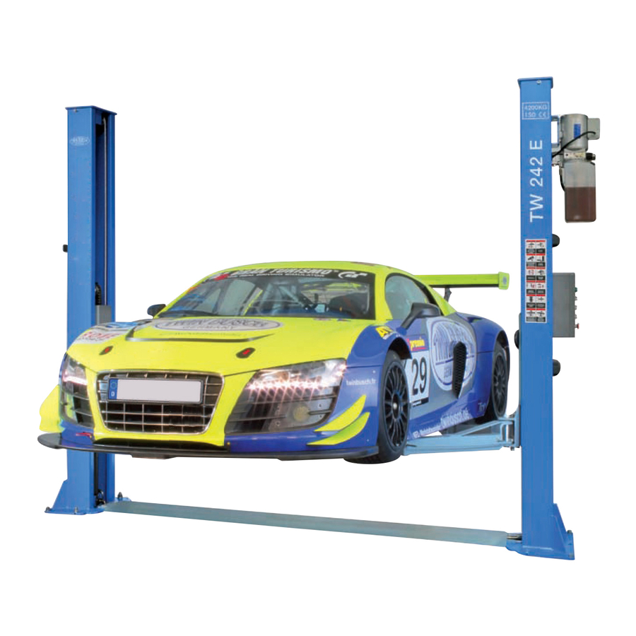
- Page 1 TW 242 E Basic-Line Lift Electronic INSTALLATION, OPERATION AND MAINTENANCE MANUAL Always read the manual carefully to avoid damage or accidents through misuse.
- Page 2 TWIN BUSCH GmbH INDEX 1. Important warnings 4 - 5 1.1 Warnings 1.2 Qualified personnel 1.3 Safety warnings 1.4 Warnings 1.5 Noise level 1.6 Training 2. General overview 2.1 General description 2.2 Technical Data 2.3 Construction plan 3. Installation instructions 8-14 3.1 Before Installing...
- Page 3 TWIN BUSCH GmbH Safety warnings 1.1 Important notice The manufacturer will take no responsibility for improper installation, improper usage, overloading or non suitable ground for mounting the lift. This model is specially designed for lifting vehicles up to the specified weight. Usage for other purposes will not be covered by the manufacture or the dealer for accidents or damage.
- Page 4 TWIN BUSCH GmbH 1.4 Warning signs All safety warning labels are clearly depicted on the lift to ensure that the operator is aware of dangers during operation. Warning labels should be kept clean and replaced when damaged or missing. ATTENTION...
- Page 5 TWIN BUSCH GmbH 1.5 Noise level The Noise level of the lift should not exceed 75 decibel. 1.6 Training Only qualified trained people are allowed to operate the lift. Professional training is offered when necessary. 2. Overview of the lift 2.1 General description...
- Page 6 TWIN BUSCH GmbH 2.3 Construction of the lift Technical changes for purposes of a technical advancement as well as deviation in colour, errors and printing mistakes are reserved. page 6 of 45...
- Page 7 TWIN BUSCH GmbH 3. Installation 3.1 Before Installation 3.1.1 Needed tools and equipment Appropriate lifting equipment Hydraulic oil HLP 32 Hammer drill Set of spanners (17, 19, 22) sockets, screw drivers and Allen keys Hammer, pliers 3.1.2 Check list - Attachment 1 (Pack list)
- Page 8 TWIN BUSCH GmbH Step 7: Mount the safety mechanism and the electro magnets then the protection cover. Safety latch Bracket Electro magnet M5*10 Screw Safety latch Electro magnet M6*16 Screw Protection cover Mount the Limit switch on the upper inner side oft he main post.
- Page 9 TWIN BUSCH GmbH Step 7:Fitting the bottom protection plate. Raise the lift to about 800mm and activate the safety locks, then mount the base plate Screw/dowel bottom trough plate Step8: Connecting the steel cables. 1. Raise carriages on both sides approximately 800mm above the ground.
- Page 10 TWIN BUSCH GmbH Step9: Connect the oil hose. Connect the oil hose as in the following diagram. Technical changes for purposes of a technical advancement as well as deviation in colour, errors and printing mistakes are reserved. page 10 of 45...
- Page 11 TWIN BUSCH GmbH Step10: Mounting the Pump and the control box. 1. Mount the power unit onto the main post. 2. Connect the pump with the control box as in the wiring diagram. Step 11: Install the oil hose protector.
- Page 12 TWIN BUSCH GmbH Oil hose protectoion plate Step12: Install the lifting arms. Connect the lifting arm and the carriage with the pins. Install the swing arms on the carriages and make sure the safety lock and half moon are correctly positioned.
- Page 13 TWIN BUSCH GmbH Check list after installation To check Are the posts vertical? (90°) Are both posts parallel to each other? Are all oil connections correct? Are the cables secure and tight? Are the lifting arms correctly mounted? Are all electrical connections correct?
- Page 14 TWIN BUSCH GmbH 4.3 Flow chart for operation Raising Lowering Start Start Turn on the power switch Turn on the power switch Press the DOWN button Press UP button The lift is lowered Motor drives the gear pump work Cylinder piston drives the chain work...
- Page 15 TWIN BUSCH GmbH 4.5 Emergency lowering in case of power cut When the safety mechanism is not engaged: a. Release and hold all four Electromagnets, on the posts simultaneously. Electromagnet b. Turn the valve screw manually. „CLOSE“ (Press the screw in and turn left to open and right to close.„OPEN“, Electromagnetic valve Technical changes for purposes of a technical advancement as well as deviation in colour, errors and printing mistakes are reserved.
- Page 16 TWIN BUSCH GmbH When t he safety mechanism is engaged: a. Open the hydraulic plug to enable the connection of a manual pump. (Optional). Hydraulic- Motor connection Hydraulic plug (Hydraulic connection) Oil tank b. Press the pump lever to fill the cylinder with oil (optional) the safety can now be released.
- Page 17 TWIN BUSCH GmbH Trouble shooting Attention: Please don’t hesitate to contact us if you can’t solve the problem yourself. We will help as soon as possible. To help us help you please send a detailed description of your problem with pictures if possible.
- Page 18 TWIN BUSCH GmbH Maintenance Simple low cost maintenance will enhance the safety and prolong the life of your lift. The service intervals can be chosen in between working times. Here are the lubrication (greasing points): Description Cable pulley (top) Steel cable...
- Page 19 TWIN BUSCH GmbH Attachment (Pack List) Material # Name Drawing# Property Power side post assembly FL-8224E-A1 Assembly Post assembly FL-8224E-A2 Assembly Carriage assembly FL-8224E-A3 Assembly Power unit Assembly Oil cylinder FL-8224-A4-B3 Assembly Drive oil cylinder FL-8224-A4-B2 Assembly Electrical system Assembly...
- Page 20 TWIN BUSCH GmbH Attachment 2, Dimensions diagram Technical changes for purposes of a technical advancement as well as deviation in colour, errors and printing mistakes are reserved. page 20 of 45...
- Page 21 Model (mm) (mm) (mm) (kg) (kg) (kg) (kg) TW 242 E 2400 2900 2300 1900 2300 1900 Technical changes for purposes of a technical advancement as well as deviation in colour, errors and printing mistakes are reserved. page 21 of 45...
- Page 22 TWIN BUSCH GmbH Attachment 3, Diagram for ground fixtures New Concrete 28 days drying Concrete thickness >200 mm Expansion bolts: M18x10 Floor level <5 mm Technical changes for purposes of a technical advancement as well as deviation in colour, errors and printing mistakes are reserved.
- Page 23 TWIN BUSCH GmbH Requirements for the concrete floor: Concrete C20 / 25 according to DIN 1045-2 (Previously known as DIN 1045 concrete B25). Horizontal, accuracy of flatness smaller than 5 mm (0.2”). New concrete must dry for 28 days.
- Page 24 TWIN BUSCH GmbH Other requirements: The surrounding ground must be suitable for the load, for example, no sand asphalt, etc.. If in doubt, the foundation should always be checked by a structural engineer. In case of frost, please note the following: In cases of freezing the concrete should have exposure class XF4.
- Page 25 TWIN BUSCH GmbH Attachment 4, Hydraulic system Main cylinder Assistant cylinder E-magnetic unloading valve Throttle valve Motor Coupling Gear pump Single-way valve Overflow valve 10. Anti-surge valve 11. Cushion valve 12. Emergent unloading valve Attachment 5, Wiring diagram Technical changes for purposes of a technical advancement as well as deviation in colour, errors and printing mistakes are reserved.
- Page 26 TWIN BUSCH GmbH Single phase Three phase Technical changes for purposes of a technical advancement as well as deviation in colour, errors and printing mistakes are reserved. page 26 of 45...
- Page 27 TWIN BUSCH GmbH Technical changes for purposes of a technical advancement as well as deviation in colour, errors and printing mistakes are reserved. page 27 of 45...
- Page 28 TWIN BUSCH GmbH Technical changes for purposes of a technical advancement as well as deviation in colour, errors and printing mistakes are reserved. page 28 of 45...
- Page 29 TWIN BUSCH GmbH Technical changes for purposes of a technical advancement as well as deviation in colour, errors and printing mistakes are reserved. page 29 of 45...
- Page 30 TWIN BUSCH GmbH Technical changes for purposes of a technical advancement as well as deviation in colour, errors and printing mistakes are reserved. page 30 of 45...
- Page 31 TWIN BUSCH GmbH Attachment 6, Explosion drawings Name Motor Hydraulic block Overflow valve Removable plug Cushion valve Oil absorbing pipe Oil filter Throttle valve Oil pipe tie-in E-magnetic unloading valve One-way valve Gear pump Plastic oil tank Oil tank cover Oil back pipe Technical changes for purposes of a technical advancement as well as deviation in colour, errors and printing mistakes are reserved.
- Page 32 TWIN BUSCH GmbH Material # Name Drawing# Property Note FL8224-A6 Steel cable L=8820mm Assembly Hex nut M16 GB/T610-2000 Standard Class C flat washer M16 GB/T95-1985 Standard Expansion bolt M18*180 Standard Material # Name Drawing# Property Note Rubber oil hose L=2900...
- Page 33 TWIN BUSCH GmbH Material # Name Drawing# Property Note FL-8224E-A1-B3 Positioning block Zinc-plating FL-8224E-A1-B2 Safety locking plate Zinc-plating GB/T818-2000 Cross cap screw M6*16 Standard GB/T818-2000 Cross cap screw M5*10 Standard FL-8224E-A1-B5 Electromagnet protection cover Plastic FL-8224-A1-B6 φ20 hose clip Rubber...
- Page 34 TWIN BUSCH GmbH Material # Name Drawing# Property Note Type B circlip 25 GB/T894.2-1986 Standard Bearing 2516 SF-1 Standard FL-8224-A1-B2 Down pulley Zinc-plating FL-8224-A3-B6 Slider Nylon FL-8224-A3-B2 Pulling rod Zinc-plating FL-8224-A3-B5 Pressure spring Zinc-plating FL-8224-A3-B6 Teeth block Zinc-plating Elastic pin 5*35 GB/T879.1-2000...
- Page 35 TWIN BUSCH GmbH Technical changes for purposes of a technical advancement as well as deviation in colour, errors and printing mistakes are reserved. page 35 of 45...
- Page 36 TWIN BUSCH GmbH Material # Name Drawing# Property Note FL-8224-A1-B3 Top plate Assembly Class C flat washer M12 GB/T95-1985 Standard Spring washer M12 GB/T93-1987 Standard Hex head full swivel screw M12*20 GB/T5781-2000 Standard Hex nut M6 GB/T6170-2000 Standard Class C flat washer M6...
- Page 37 TWIN BUSCH GmbH Attachment 7, Spare parts list Material # Name Spec. Pic. Note Power switch LW26GS-20/04 Button LAY711BN12 Power indicator AD17-22G-AC24 JBK3-160VA400V-24V Bk 一 160VA110V 一 Transformer 24V 一 60HZ CJX2-1210/AC24V AC contactor CJX2-3210- AC24V DZ47-63 C16/3P Circuit breaker...
- Page 38 TWIN BUSCH GmbH Material # Name Spec. Pic. Note time relay ST6PA-5S/AC24V Time relay holder PYF-08AE Control box 380*260*135 Technical changes for purposes of a technical advancement as well as deviation in colour, errors and printing mistakes are reserved. page 38 of 45...
- Page 39 TWIN BUSCH GmbH Technical changes for purposes of a technical advancement as well as deviation in colour, errors and printing mistakes are reserved. page 39 of 45...
- Page 40 TWIN BUSCH GmbH Technical changes for purposes of a technical advancement as well as deviation in colour, errors and printing mistakes are reserved. page 40 of 45...
- Page 41 TWIN BUSCH GmbH Technical changes for purposes of a technical advancement as well as deviation in colour, errors and printing mistakes are reserved. page 41 of 45...
- Page 42 TWIN BUSCH GmbH Technical changes for purposes of a technical advancement as well as deviation in colour, errors and printing mistakes are reserved. page 42 of 45...
- Page 43 TWIN BUSCH GmbH Technical changes for purposes of a technical advancement as well as deviation in colour, errors and printing mistakes are reserved. page 43 of 45...
- Page 44 TWIN BUSCH GmbH Technical changes for purposes of a technical advancement as well as deviation in colour, errors and printing mistakes are reserved. page 44 of 45...
- Page 45 TWIN BUSCH GmbH Technical changes for purposes of a technical advancement as well as deviation in colour, errors and printing mistakes are reserved. page 45 of 45...
Need help?
Do you have a question about the TW 242 E and is the answer not in the manual?
Questions and answers