Advertisement
Quick Links
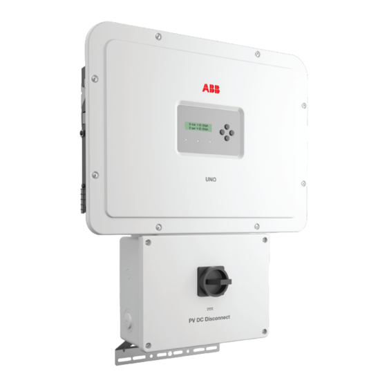
ABB solar inverters
Quick installation guide
UNO-DM-6.0-TL-PLUS-US
(6.0 kW)
EN
Before starting installation, download the product manual from www.abb.
com/solarinverters. Choose the correct country, string inverters, single phase,
choose the product and proceed to the "download" section.
Read and follow all safety and installation instructions to avoid disabling any
safety features or making the warranty invalid.
3.
Installation site and position
- Refer Datasheet/Manual to confirm that the environmental specifications have been met
- Do not install the inverter in full sun. If needed, use a sun shade to minimize solar
irradiation, especially for temperatures over 104°F/40°C.
- Do not install in closed spaces where air does not circulate freely
- Always ensure that the flow of air around the inverter is not blocked, so as to prevent
overheating.
- Do not install the equipment near flammable substances (minimum distance: 10 ft).
- Do not install the equipment on wooden walls or other flammable substances.
- Do not install in inhabited rooms or where the prolonged presence of people or animals
is expected, because of the inverter's noise level during operation. The sound level
is heavily influenced by its location (for example, the surface around the inverter, the
environment, etc.) and grid quality.
- Install on a wall or strong structure capable of bearing weight
- Install vertically with a maximum inclination as indicated in the figure
- Maintain minimum clearance from objects blocking air circulation and spacing betwe-
MAX
5° MAX
en inverter as indicated in the figures
6
- Ensure sufficient working area in front of the inverter for wiring box access
in
- If possible, install at eye level so that the display and LEDs can be seen easily
- Install at a height that takes account of the weight of the equipment
- Position multiple inverters side-by-side, maintaining minimum clearances
(measured from the outermost edge of the inverter)
- Multiple inverters can also be placed in a staggered arrangement. Minimum
4 in
clearances for staggered arrangements include width of the inverter cover
plus additional allowances for inverters arranged above or below
- All installations over 6500' high (2,000 meters) must be assessed by ABB
NO
NO
Technical Sales to determine the proper datasheet derating
Do not block access to the external AC and DC disconnects.
Please refer to the warranty terms and conditions and avoid voiding the
8
warranty with improper installation.
in
4.
Mount the inverter following the step-by-step procedure below.
Do not remove the inverter chassis cover in
adverse weather conditions (e.g. rain, snow)
or during periods of high humidity (>95%).
Components included in mounting kit
Q.TY
Wall bracket
1
T20 Wall bracket locking
screw (to be used when
2
lock springs
on the
02
bracket are missing)
(Spare part) T20 screw for
1
front cover
Jumpers for configuring
1 + 1
paralleled inputs.
ABB
XXXXXXXX
XXXXXXXX
inverters
solar
Quick
installation
guide
XXXXXXXX
XXXXXXXX
XXX
XXX
1
(QIG)
The
technical
In addition
is explained
to what
documentation
guide,
and
the
in this
the
interface
safety
and
management
software
installation
and
product
information
for the
provided
available
in the
are
website.
at the
manual
installation
t be
mus
followed.
read
and
- Position the bracket
so that it is level on the wall or pole
07
- It is the installer's responsibility to choose an appropriate
number and distribution of attachment points. The
choice must be based on the type of wall, frame or other
support, the type of anchors to be used, and their ability
to support 4 times the inverter's weight (4x33lbs=132lbs
for all models).
Depending on the type and number of attachment points,
drill the required holes to mount the bracket (see figure
detail
)
A
- Secure the bracket to the wall or frame
- If needed, make conduit cutouts in the wiring box chassis,
before the wiring box is put on the wall
- Carefully lift the inverter and hook it onto the bracket by insert-
ing the two supports in the slots on the inverter (Figure
).
B
- Proceed to anchor the inverter to the bracket by installing
the two (one each side) locking screws (Figure
B1
).
If on the bracket are present the lateral lock springs, pro-
ceed to lock the inverter by pressing the lower part toward
the wall or structure until the two springs on the bracket set
the inverter in position (Figure
).
B2
- Secure the inverter chassis bottom flange to the mounting
surface using another screw (see Figure detail
). Note
C
that the bottom flange is not a load-bearing component.
5° MAX
5° MAX
4 in
NO
NO
OK
OK
OK
OK
4 in
OK
A
1.
The installer must read this document in its entirety before installing or commissioning this equipment.
For more detailed information regarding proper installation and use of this product, refer to the product manual located at www.abb.com/solarinverters. The
labels on the inverter have the markings, main technical data and identification of the equipment and manufacturer. The technical data shown in this quick
installation guide does not replace that shown on the labels attached to the equipment.
Symbols used in the guide and on the products
These are nationally recognized test laboratory marks show-
ing certification to UL 1741 and CSA C22 No. 107.1
Hazardous voltage
General warning - Important safety information
Hot surfaces
System earth conductor (main grounding protective
earth, PE)
Equipment Grounding Conductor (EGC)
- This device complies with Part 15 of the FCC Rules. Operation is subject to the following two conditions:
(1) this device may not cause harmful interference, and (2) this device must accept any interference received, including interference that may cause undesired operation.
2.
This installation guide covers the inverter model UNO-DM-6.0-TL-PLUS-US (6 kW).
Main components
01
Display
02
LED panel
03
Keypad
04
Inverter front cover
05
Wiring box front cover
06
DC disconnect switch
01
02
03
04
05
06
5.
All power conductors will be inserter in spring clamp terminals.
The figure shows an example of how to make the wire connection:
6
in
OK
1) Insert a small flat screwdriver in the slot and lightly press the screwdriver from top to bottom;
insert the screwdriver until the spring opens.
2) Insert the cable in the spring clamp.
OK
OK
OK
3) Remove the screwdriver.
4 in
4) When connections are complete, give each wire a pull test
6.
NOTE: If a RSD device was istalled into the plant, it also will needed to connect the AC grid to allow
8
the inverter to power-up!
in
The installer must use an external rapid shutdown device compliant with the 2014 NEC.
Automatic shutdown occurs at the rooftop box when utility power is lost or when the PV system's AC di-
sconnect switch is opened. In jurisdictions requiring a dedicated activation switch, install an emergency stop
button external to the inverter.
NO
NO
The wiring box has 24Vdc (0.4A max) on a spring-loaded terminal block to the left of the PV input area,
OK
which is designed to be used to power a RSD device.
RSD wiring terminals accommodate a wire size range of 26-12 AWG.
- Install RSD device wires in the RSD terminal block;
+24V wire to +RSD terminal, - 24V wire to - RSD terminal
7.
OK
OK
OK
Confirm the correct polarity in the input strings.
Confirm there is no ground leakage current in the PV array.
When exposed to sunlight, the PV panels supply DC direct voltage to the inverter.
The inverter's DC switch disconnects the DC current from the PV panels. In the "OFF" position the inverter will stop producing power, but
DOES NOT disconnect the AC from the grid. To prevent electrocution hazards, all the connection operations must be carried out with the
external AC disconnect switch, downstream of the inverter (grid side), open and locked out.
The transformerless design requires that the PV array to be floating with respect to ground per NEC 690.35.
DC PV string wire must be listed PV wire per NEC 690.35 rated minimum 600V.
PV output conductors (wiring) must consist of sheathed (jacketed) multi-conductor cables or single insulated conductors (wires) which
must be installed in an approved raceway. These conductors must be isolated from the enclosure and system grounding, as required by
NEC 690.35. This is the responsibility of the installer.
Confirm that the maximum PV array short circuit current for each DC input channel is within the inverter specification (see table in Section
14). Array equipment grounding must be installed per the requirements of the NEC and is the responsibility of the installer. A configuration
program that can help to correctly size the photovoltaic system is available on at http://www.stringsizer.abb.com.
- Turn the DC switch OFF
- Loosen the four captive screws on the wiring box cover (Torx 20) and remove the cover
- Pass the DC wires through the openings dedicated to the DC conduit.
Conduit must be sealed using water-tight fittings to maintain NEMA Type 4X enclosure integrity.
B
Installer should follow conduit manufacturers' guidelines and best practices.
- Connect the DC wiring to DC input terminal blocks
Connect the strings in either independent or parallel mode, following the appropriate set of instructions below:
B1
Independent mode configuration
In case of two PV arrays, if each of them has a current rating lower than the
maximum current rating for a single inverter channel, they may be connected
as "IND" array, each with its own MPPT. In this case, do nothing with the
jumper wires which came with the inverters.
- Connect the positive side of the first PV array to +IN1, and its negative side to -IN1.
- Connect the positive side of the second PV array to +IN2 and its negative side to -IN2.
Up to four strings can be connected in independent mode.
B2
- During commissioning, confirm that the input mode is set to IND. The input
mode is set using the display menu. Settings>Input Mode>Independent.
If connecting a single array, configure the inverter for parallel input mode.
MPPT2
String2
MPPT1
String2
C
IMPORTANT SAFETY INSTRUCTIONS
SAVE THESE INSTRUCTIONS -- KEEP IN A SAFE PLACE!
ø
+
07
Wall bracket
13
AC output terminal blocks
08
14
Lock spring (where present)
Wiring box
09
Heatsink
15
Wi-Fi antenna (-B models only)
UNO-DM-PLUS Ethernet COM KIT or
Protective Earth (PE) connection
10
16
UNO-DM-COM KIT board (optional)
point
Conduit drill out sizes 3/4", 1" (drill out
11
Inverter
17
markings on back side)
DC input terminal blocks
12
18
lower flange
(two MPPT)
08
24
07
09
10
11
23
12
06
13
14
15
16
NO
NO
OK
OK
OK
OK
OK
. DC wiring terminals are spring pressure type and accommodate a wire size range of 20-8 AWG.
12
Parallel mode configuration
If a PV array's output current is more than the rating for a single inverter
channel:
- connect the red jumper wire between the +IN1 and +IN2 terminal block
inputs. Then connect the jumper wire black wire between the -IN1 and -IN2
terminals. Remember later to set the input mode to PAR from the display
(Settings>Input Mode>Parallel).
- Connect the array to the IN1 (MPPT1) and IN2 (MPPT2) input positions,
running separate wires for positive (+) and negative (-) for each array.
CAUTION
REFER TO LOCAL CODE
FOR WIRE SIZE
ATTENTION
FAIRE RÉFERENCE À LA
LÉGISLATION LOCALE POUR
LA DIMENSION DU CABLE
MPPT2
String1
MPPT1
String1
Phase
Direct and alternating currents, respectively
-
Positive pole and negative pole of the input voltage (DC)
Stored energy discharge time
10
Consult product manual
1/2" communication conduit
19
drill out
Markings for 3/4" or 1" conduit
20
drill outs
21
Opening for 3/4" AC conduit
22
Lock screw position
Power supply for rapid shutdown
23
(RSD) terminal blocks
24
Locking Screw
Back view
Left view
Front view
Right view
19
20
Bottom view
CAUTION
REFER TO LOCAL CODE
FOR WIRE SIZE
ATTENTION
FAIRE RÉFERENCE À LA
LÉGISLATION LOCALE POU
LA DIMENSION DU CABLE
PARALLEL
CAUTION
JUMPERS
REFER TO LOCAL CODE
FOR WIRE SIZE
ATTENTION
FAIRE RÉFERENCE À LA
LÉGISLATION LOCALE POUR
LA DIMENSION DU CABLE
MPPT2
MPPT1
17
18
22
06
21
Advertisement

Related Manuals for ABB UNO-DM-6.0-TL-PLUS-US


Summary of Contents for ABB UNO-DM-6.0-TL-PLUS-US
- Page 1 Quick installation guide For more detailed information regarding proper installation and use of this product, refer to the product manual located at www.abb.com/solarinverters. The labels on the inverter have the markings, main technical data and identification of the equipment and manufacturer. The technical data shown in this quick UNO-DM-6.0-TL-PLUS-US...
- Page 2 Consulter le manual d'installation pour les instructions de câblage. inverter: a network with the name ABB-XX-XX-XX-XX-XX-XX will appear in the list of networks, where “X” is a hex digit of the MAC address (MAC address can be found on the “Wireless Identification Label” placed on the side of the inverter or previously applied to this quick installation guide - see cover page).