Sony ICD-SX700 Service Manual
Hide thumbs
Also See for ICD-SX700:
- Operating instructions manual (136 pages) ,
- Quick start manual (56 pages) ,
- Operating instructions manual (147 pages)
Table of Contents
Advertisement
Quick Links
SERVICE MANUAL
Ver. 1.0 2009.01
Note:
Be sure to keep your PC used for service and
checking of this unit always updated with the
latest version of your anti-virus software.
In case a virus affected unit was found during
service, contact your Service Headquarters.
IC recorder section
Capacity (User available capacity)
ICD-SX700/SX700D: 1 GB
(approx. 970 MB = 1,017,610,240 Byte)
ICD-SX800/SX800D: 2 GB
(approx. 1.9 GB = 2,047,737,856 Byte)
ICD-SX900: 4 GB
(approx. 3.82 GB = 4,108,156,928 Byte)
A part of the memory capacity is used as a
management area.
Recording time
Maximum recording time
When all messages are recorded with
the same recording mode, the maximum
recording time of all the folders is as
follows.
ICD-SX700/SX700D
LPCM 44/16 mode LPCM 22/16 mode MP3 192k mode
1 hr. 30 min.
3 hr. 10 min.
11 hr. 40 min.
MP3 128k mode
MP3 48k mode
LPEC STHQ mode
17 hr. 35 min.
46 hr. 55 min.
17 hr. 20 min.
LPEC ST mode
LPEC STLP mode LPEC SP mode
45 hr. 45 min.
88 hr. 10 min.
139 hr. 35 min.
LPEC LP mode
372 hr. 25 min.
ICD-SX800/SX800D
LPCM 44/16 mode LPCM 22/16 mode MP3 192k mode
3 hr. 10 min.
6 hr. 25 min.
23 hr. 35 min.
MP3 128k mode
MP3 48k mode
LPEC STHQ mode
35 hr. 25 min.
94 hr. 40 min.
34 hr. 55 min.
LPEC ST mode
LPEC STLP mode LPEC SP mode
92 hr. 15 min.
177 hr. 40 min.
281 hr. 20 min.
LPEC LP mode
750 hr. 15 min.
Sony Corporation
9-889-398-01
2009A04-1
Audio&Video Business Group
©
2009.01
Published by Sony Techno Create Corporation
ICD-SX700/SX700D/SX800/
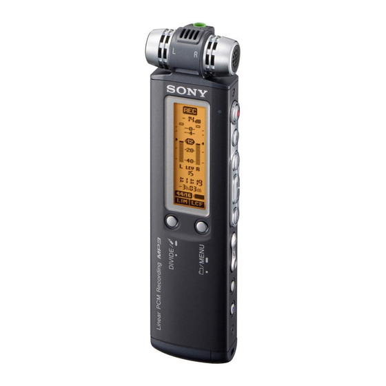
Photo: ICD-SX700
SPECIFICATIONS
ICD-SX900
LPCM 44/16 mode LPCM 22/16 mode MP3 192k mode
6 hr. 25 min.
12 hr. 50 min.
47 hr. 30 min.
MP3 128k mode
MP3 48k mode
LPEC STHQ mode
71 hr. 15 min.
190 hr. 5 min.
70 hr. 10 min.
LPEC ST mode
LPEC STLP mode LPEC SP mode
185 hr. 20 min.
356 hr. 45 min.
564 hr. 40 min.
LPEC LP mode
1,505 hr. 55 min.
(hr. : hours/min. : minutes)
Frequency range
• LPCM 44/16: 50 - 20,000 Hz
• LPCM 22/16: 50 - 10,000 Hz
• MP3 192k: 50 - 16,000 Hz
• MP3 128 k: 50 - 16,000 Hz
• MP3 48 k: 50 - 14,000 Hz
• LPEC STHQ: 50 - 20,000 Hz
• LPEC ST: 50 - 16,500 Hz
• LPEC STLP: 50 - 7,000 Hz
• LPEC SP: 50 - 6,000 Hz
• LPEC LP: 50 - 3,500 Hz
Bit rates and sampling frequencies for
MP3 fi les*
2
Bit rate: 32 - 320 kbps, VBR
Sampling frequencies: 16/22.05/24/32/44.1/
48 kHz
2
*
The playback of MP3 fi les recorded using
the IC recorder is also supported.
Not all encoders are supported.
SX800D/SX900
US Model
Canadian Model
ICD-SX700/SX700D
AEP Model
E Model
ICD-SX700/SX800/SX800D
Chinese Model
Korea Model
ICD-SX700/SX800/SX900
Taiwan Model
ICD-SX900
Bit rate and sampling frequencies*
WMA fi les
Bit rate: 32 - 192 kbps, VBR
Sampling frequencies: 44.1 kHz
*
3
WMA Ver. 9 is compatible, however, MBR
(Multi Bit Rate), Lossless, Professional, and
Voice are not supported.
A fi le of which copyright is protected cannot
be played back.
Not all encoders are supported.
General
Speaker
Approx. 16 mm (
in.) dia.
13/32
Power output
150 mW
Input/Output
• Microphone jack (minijack, stereo)
– input for plug in power, minimum input
level 0.9 mV, 3 kilohms or lower impedance
microphone
• Headphone jack (minijack, stereo)
– output for 8 - 300 ohms headphones
• USB connector
– High-Speed USB compatible
Playback speed control (DPC)
–75% to +200%
– Continued on next page –
IC RECORDER
3
for
Advertisement
Table of Contents

Related Manuals for Sony ICD-SX700


Summary of Contents for Sony ICD-SX700
- Page 1 LPEC STLP mode LPEC SP mode 92 hr. 15 min. 177 hr. 40 min. 281 hr. 20 min. LPEC LP mode 750 hr. 15 min. IC RECORDER Sony Corporation 9-889-398-01 2009A04-1 Audio&Video Business Group © 2009.01 Published by Sony Techno Create Corporation...
- Page 2 ICD-SX700/SX700D/SX800/SX800D/SX900 Power requirements NOTES ON CHIP COMPONENT REPLACEMENT Two LR03 (size AAA) alkaline batteries: 3.0 V DC • Never reuse a disconnected chip component. Two NH-AAA rechargeable batteries: 2.4 V DC • Notice that the minus side of a tantalum capacitor may be dam- aged by heat.
-
Page 3: Table Of Contents
ICD-SX700/SX700D/SX800/SX800D/SX900 TABLE OF CONTENTS GENERAL ..............DISASSEMBLY 2-1. Speaker Assy (SP001) ............. 2-2. Battery Case Lid Assy ............. 2-3. Case Assy ................ 2-4. Audio Board Section, Chassis Section, Switch Board ..2-5. Main Board ..............2-6. Liquid Crystal Display Panel (LCD101) ...... -
Page 4: General
ICD-SX700/SX700D/SX800/SX800D/SX900 SECTION 1 GENERAL This section is extracted from instruction manual. Rear Bookmark indicator Index to Parts and Appears when a bookmark is set for Controls a message. Alarm indicator Refer to the pages indicated in parentheses for details. Appears when the alarm is set for a message. - Page 5 ICD-SX700/SX700D/SX800/SX800D/SX900 Display during recording Press to select “AUTO” Step 2: Setting the or “MANUAL” and press Clock When you selected “AUTO, ” the clock is automatically adjusted using the clock in the computer connected to the IC recorder and on which the supplied Digital Voice Editor software is started.
-
Page 6: Disassembly
ICD-SX700/SX700D/SX800/SX800D/SX900 SECTION 2 DISASSEMBLY • This set can be disassembled in the order shown below. 2-1. SPEAKER ASSY (SP001) (Page 7) 2-2. BATTERY CASE LID ASSY (Page 7) 2-3. CASE ASSY (Page 8) 2-4. AUDIO BOARD SECTION, CHASSIS SECTION, SWITCH BOARD (Page 8) 2-5. -
Page 7: Speaker Assy (Sp001)
ICD-SX700/SX700D/SX800/SX800D/SX900 Note: Follow the disassembly procedure in the numerical order given. 2-1. SPEAKER ASSY (SP001) base two claws two screws (M1.4) three knobs (hold) speaker assy (SP001) claw claw claw claw knob (side) 2-2. BATTERY CASE LID ASSY screw (M1.4) -
Page 8: Case Assy
ICD-SX700/SX700D/SX800/SX800D/SX900 2-3. CASE ASSY screw (M1.4) spacer (ornamental belt) chassis assy When assembling the chassis assy, adjust the switches in the direction of the arrow. switch screw (M1.4) switch switch case assy switch 2-4. AUDIO BOARD SECTION, CHASSIS SECTION, SWITCH BOARD Sheet (microphone jack) attachment position is shown. -
Page 9: Main Board
ICD-SX700/SX700D/SX800/SX800D/SX900 2-5. MAIN BOARD two claws cover (chassis) two claws MAIN board claw two claws cushion (battery terminal +) claw claw cushion (battery terminal) 2-6. LIQUID CRYSTAL DISPLAY PANEL (LCD101) light guide plate When installing the liquid crystal display panel... -
Page 10: Audio Board
ICD-SX700/SX700D/SX800/SX800D/SX900 2-7. AUDIO BOARD Remove the four solders. Remove the seven solders. microphone assy microphone assy black blue black black gray black black white yellow AUDIO board AUDIO board 2-8. JACK BOARD microphone assy JACK board cover (headphone jack) two screws... -
Page 11: Microphone Cap, Microphone Holder
ICD-SX700/SX700D/SX800/SX800D/SX900 2-9. MICROPHONE CAP, MICROPHONE HOLDER microphone cap Convex part Concave part microphone holder Concave part microphone cap Convex part Take note of the orientation and the direction when assembling. And take note of the mark’s direction. mark 2-10. MIC101, MIC102, MIC103... -
Page 12: Test Mode
ICD-SX700/SX700D/SX800/SX800D/SX900 SECTION 3 TEST MODE [Test Mode] 1. Version test The following checks can be implemented using the Test Mode. • Version of the respective modules are verifi ed. F/W version of How to Enter the Test Mode Boot loader •... - Page 13 ICD-SX700/SX700D/SX800/SX800D/SX900 3. Loop test 8. Cluster Num test Execute the DSP LOOP BACK. • This is the cluster number display to be used for engineering design. Test Key SWITCH Description • Press the [ ] button to return the test mode screen.
- Page 14 ICD-SX700/SX700D/SX800/SX800D/SX900 18. Menu lnit • Press the [ ] button to enter the menu initialization. • Press the [ ] button to return to the test mode screen. 19. Convert test • This is the conversion out to be used for engineering de- sign.
-
Page 15: Diagrams
ICD-SX700/SX700D/SX800/SX800D/SX900 SECTION 4 DIAGRAMS 4-1. BLOCK DIAGRAM – MAIN1 Section – SWITCH Q3660 D3607 ADC, DAC, HEADPHONE AMP IC3901 SELECTOR SELECTOR IC3203 D3606 IC3655 M101 (MIC) 2 NO1 IC3202 POWER AMP COM1 IC3403 4 NC1 COM1 3 A+INPUT HPCOM/MONO OUTP... -
Page 16: Block Diagram -Main2 Section
ICD-SX700/SX700D/SX800/SX800D/SX900 4-2. BLOCK DIAGRAM – MAIN2 Section – SDRAM IC2602 SDR_CSZ0 SDR_BA1 G7 BA0 SDR_BA0 SDR_WEZ SDR_RASZ SDR_CASZ SDR_CKE0 F3 CKE SDR_CLK F2 CLK SDR_DQM1 DQM1 SDR_DQM0 E8 LDQM R1,R8,N1, A2,A8,B1 N2,N3,N4, B2,B8,B9 DQ0-7 N5N8,M4, SDR_DATA0-15 C1,C2,C8 DQ8-12 M5,M8,P1, C9,D1,D2... - Page 17 ICD-SX700/SX700D/SX800/SX800D/SX900 THIS NOTE IS COMMON FOR PRINTED WIRING BOARDS AND SCHEMATIC DIAGRAMS. (In addition to this, the necessary note is printed in each block.) For Printed Wiring Boards. For Schematic Diagrams. Note: Note: • All capacitors are in μF unless otherwise noted. (p: pF) 50 •...
-
Page 18: Printed Wiring Board -Audio Section (1/2)
ICD-SX700/SX700D/SX800/SX800D/SX900 4-3. PRINTED WIRING BOARD – AUDIO Section (1/2) – • : Uses unleaded solder. AUDIO BOARD (SIDE A) D5002,5004,5005 (LCD BACK LIGHT) D5005 D5004 D5002 B C3688 Q3657 S6001 2 1 3 DIVIDE / C3999 R6003 S6004 / MENU... -
Page 19: Printed Wiring Board -Audio Section (2/2)
ICD-SX700/SX700D/SX800/SX800D/SX900 4-4. PRINTED WIRING BOARD – AUDIO Section (2/2) – • : Uses unleaded solder. AUDIO BOARD (SIDE B) J3201 PLUG IN POWER S6013 LCD101 DIRECTNL LIQUID CRYSTAL DISPLAY PANEL ON (MONO) BT1602 R6019 CN5002 FB3201 LITHIUM Q5001 RECHARGEABLE R3207... -
Page 20: Schematic Diagram -Audio Section (1/2)
ICD-SX700/SX700D/SX800/SX800D/SX900 4-5. SCHEMATIC DIAGRAM – AUDIO Section (1/2) – AUDIO BOARD (1/2) Q3660 R3910 3LP01S-K-TL-E 2 . 9 ( 0 ) SWITCH VDD_STMIC Q3657 2 . 9 ( 0 ) C3689 3LP01S-K-TL-E SWITCH 6.3V 2 ( 0 ) D3606 R3738 2 . -
Page 21: Schematic Diagram -Audio Section (2/2)
ICD-SX700/SX700D/SX800/SX800D/SX900 4-6. SCHEMATIC DIAGRAM – AUDIO Section (2/2) – • See page 31 for IC Block Diagram. AUDIO BOARD (2/2) R6032 BKBAT+ 4.7k BT1602 C6033 LITHIUM RECHARGEABLE BATTERY BKBAT- AUDIO VDD_HP BOARD MICIN_R ( 1 / 2 ) (Page 20) -
Page 22: Printed Wiring Board -Main Section (1/2)
ICD-SX700/SX700D/SX800/SX800D/SX900 4-7. PRINTED WIRING BOARD – MAIN Section (1/2) – • : Uses unleaded solder. MAIN BOARD (SIDE A) (Page 19) AUDIO BOARD CN7001 IC8002 IC1603 IC8001 R1815 IC3404 Q1665 R1679 Q3402 C1803 R1401 C1608 CN1001 C3403 R8513 C1416 C1419... -
Page 23: Printed Wiring Board -Main Section (2/2)
ICD-SX700/SX700D/SX800/SX800D/SX900 4-8. PRINTED WIRING BOARD – MAIN Section (2/2) – • : Uses unleaded solder. MAIN BOARD (SIDE B) S6014 S6016 S6015 NOISE CUT (SPEED CTRL) HOLD JL1615 C6031 R6017 IC3403 S6014 S6016 S6015 C3410 Q1603 R1604 R6006 R1606 R1609... -
Page 24: Schematic Diagram -Main Section (1/5)
ICD-SX700/SX700D/SX800/SX800D/SX900 4-9. SCHEMATIC DIAGRAM – MAIN Section (1/5) – • See page 33 for IC Pin Function Description. MAIN BOARD (1/5) VDD_GP2 MAIN BOARD Q6001 VDD_ANA UNR31A400LS0 ( 3 / 5 ) VDD_HP (Page 26) SWITCH VDD_LOG R6025 2 . 8 2 . -
Page 25: Schematic Diagram -Main Section (2/5)
ICD-SX700/SX700D/SX800/SX800D/SX900 4-10. SCHEMATIC DIAGRAM – MAIN Section (2/5) – ( 2 / 5 ) MAIN BOARD VDD_SDR C2602 C2604 C2606 C2608 MAIN 0.0022 0.22 0.22 0.0022 BOARD ( 1 / 5 ) ( 3 / 5 ) (Page 24, 26) -
Page 26: Schematic Diagram -Main Section (3/5)
ICD-SX700/SX700D/SX800/SX800D/SX900 4-11. SCHEMATIC DIAGRAM – MAIN Section (3/5) – (Page 28) (Page 24, 27, 28) (Page 24, 25) (Page 24) MAIN BOARD ( 1 / 5 ) MAIN BOARD MAIN BOARD MAIN BOARD ( 1 / 5 )( 2 / 5 ) -
Page 27: Schematic Diagram -Main Section (4/5)
ICD-SX700/SX700D/SX800/SX800D/SX900 4-12. SCHEMATIC DIAGRAM – MAIN Section (4/5) – MAIN BOARD ( 4 / 5 ) IC8501 JL8501 +3.1 V REG IC8501 XC6215B312GR 3 . 1 3 . 3 VDD_USB31 VOUT MAIN BOARD VDD_DDCOUT33 1 . 8 ( 1 / 5 )( 3 / 5 )( 5 / 5 ) -
Page 28: Schematic Diagram -Main Section (5/5)
ICD-SX700/SX700D/SX800/SX800D/SX900 4-13. SCHEMATIC DIAGRAM – MAIN Section (5/5) – • See page 32 for IC Block Diagram. MAIN BOARD ( 5 / 5 ) SP_XMUTE_AA1 MAIN BOARD ( 1 / 5 ) IC3404 (Page 24) XC6219C292MR SP_PWR_AA2 C3403 3 . 3... -
Page 29: 4-14. Printed Wiring Boards - Function Section
ICD-SX700/SX700D/SX800/SX800D/SX900 4-14. PRINTED WIRING BOARDS – FUNCTION Section – • : Uses unleaded solder. HPJACK BOARD (SIDE A) HPJACK BOARD (SIDE B) R3404 BLACK J3301 JL3414 JL3413 R3403 J3301 R3402 YELLOW AUDIO BOARD JL3412 GRAY JL3411 (Page 19) (12) 1-872-143-... -
Page 30: 4-15. Schematic Diagram - Function Section
ICD-SX700/SX700D/SX800/SX800D/SX900 4-15. SCHEMATIC DIAGRAM – FUNCTION Section – (Page 21) AUDIO BOARD (2/2) CN7002 D5004 CL-375HR/YG-D-TS SW BOARD (OPERATION) C6005 R6012 R6007 R6009 R6011 R6013 R6014 R6015 2.2k 2.2k 4.7k 2.2k C6006 0.001 S6008 S6006 S6005 S6507 S6511 S6002 S6012... - Page 31 ICD-SX700/SX700D/SX800/SX800D/SX900 • IC Block Diagrams IC3901 PCM3794RHBR (AUDIO Board (2/2)) AIN2R AIN3L Serial Interface AIN3R (SOI/I2C) MUX1 MUX2 MUX3 MUX4 Audio Interface Mute DOUT AIN3R DGND Clock 20 V SCKI Manager 19 AGND Power Up/Down Manager Power on +6 to -70dB...
- Page 32 ICD-SX700/SX700D/SX800/SX800D/SX900 IC3403 SM6801AB-G-EL (MAIN Board (5/5)) DRCN MUTE VDD1 POWER DOWN, PROTECTION BIAS 12 OUTP VREF1 VREF LEVEL BUFFER 10 OUTN SHIFTER – Modulator 11 VSS2 LEVEL BUFFER SHIFTER – 9 VDD3...
- Page 33 ICD-SX700/SX700D/SX800/SX800D/SX900 • IC Pin Function Description MAIN BOARD IC1001 MC-10051BF1-FAE-A (SYSTEM CONTROLLER) Pin No. Pin Name Description — (Used to fi x solder ball to mount IC on board. Open) — (Used to fi x solder ball to mount IC on board. Open) —...
- Page 34 ICD-SX700/SX700D/SX800/SX800D/SX900 Pin No. Pin Name Description NAND_CEZ1 Chip enable NAND_CEZ3 Chip enable (Not used (Open)) NAND_DA1 Address data input/output I/O_B — Power supply to I/OB ADIN3 ADC input signal 3 ADIN5 ADC input signal 5 ADIN7 ADC input signal 7 ADGND —...
- Page 35 ICD-SX700/SX700D/SX800/SX800D/SX900 Pin No. Pin Name Description NAND_DA5 Address data input/output NAND_DA8 Address data input/output (Not used (Open)) NAND_DA7 Address data input/output NAND_CLE Command latch enable BATSEL Battery connection/On terminal SWBAT Power supply logic output CAPBTDL Power supply logic output CAPADDL...
- Page 36 ICD-SX700/SX700D/SX800/SX800D/SX900 Pin No. Pin Name Description AB0_A1 Address output AB0_A2 Address output AB0_D8 Data input/output AB0_D9 Data input/output AB0_D7 Data input/output AB0_D6 Data input/output CHGADP Battery charge control input I/O_A — Power supply to I/OA I/O_A — Power supply to I/OA I/O_A —...
- Page 37 ICD-SX700/SX700D/SX800/SX800D/SX900 Pin No. Pin Name Description SDR_DATA19 Read/write data (Not used (Open)) NAND_DA4 Address data input/output — — Not used (Open) — — LCD_B1 B data (Not used (Open)) LCD_B2 B data (Not used (Open)) LCD_B3 B data (Not used (Open))
- Page 38 ICD-SX700/SX700D/SX800/SX800D/SX900 Pin No. Pin Name Description LCD_PXCLK Pixel clock (Not used (Open)) — Not used (Open) I/O_A — Power supply to I/OA I/O_A — Power supply to I/OA SDR_DATA0 Read/write data SDR_DQM3 Write data mask (Not used (Open)) SDR_DQM2 Write data mask (Not used (Open))
- Page 39 ICD-SX700/SX700D/SX800/SX800D/SX900 Pin No. Pin Name Description VPLL REGPLL power output terminal (1.2V) Crystal connection/On terminal I/O_A — Power supply to I/OA I/O_A — Power supply to I/OA I/O_A — Power supply to I/OA SDR_A6 SDR address output SDR_A5 SDR address output...
- Page 40 ICD-SX700/SX700D/SX800/SX800D/SX900 Pin No. Pin Name Description GPI/O11 Input/output and interrupt input to general purpose I/O GPI/O10 Input/output and interrupt input to general purpose I/O GPI/O9 Input/output and interrupt input to general purpose I/O SDR_A0 SDR address output SDR_CLK Clock output...
- Page 41 ICD-SX700/SX700D/SX800/SX800D/SX900 Pin No. Pin Name Description Command response input/output (Not used (Open)) AC17 MS_BS (To be used for both of Memory Stick and SD card) Clock output (Not used (Open)) AC18 MS_SCKO (To be used for both of Memory Stick and SD card)
- Page 42 ICD-SX700/SX700D/SX800/SX800D/SX900 Pin No. Pin Name Description AE19 I/O_A — Power supply to I/OA AE20 VGP12IN REGGP1/2 power input terminal AE21 VGP3IN REGGP3 power input terminal AE22 VGP4 REGGP4 power output terminal (3.1V) AE23 VGP5 REGGP5 power output terminal (3.1V) AE24...
-
Page 43: Exploded Views
ICD-SX700/SX700D/SX800/SX800D/SX900 SECTION 5 EXPLODED VIEWS Note: • -XX and -X mean standardized parts, so • Color Indication of Appearance Parts Ex- • Abbreviation they may have some difference from the ample: : Chinese model original one. KNOB, BALANCE (WHITE) . . . (RED) CND : Canadian model ↑... -
Page 44: Chassis Section
ICD-SX700/SX700D/SX800/SX800D/SX900 5-2. CHASSIS SECTION not supplied LCD101 BT1602 Ref. No. Part No. Description Remark Ref. No. Part No. Description Remark A-1633-605-A AUDIO BOARD, COMPLETE 9-885-132-17 MAIN BOARD, COMPLETE (SX700:CH) 2-549-689-01 SHEET (SHUTTER-B), ADHESIVE 9-885-132-18 MAIN BOARD, COMPLETE (SX700:KR) 2-890-095-01 TERMINAL (DETECTION), BATTERY... -
Page 45: Microphone Section
ICD-SX700/SX700D/SX800/SX800D/SX900 5-3. MICROPHONE SECTION MIC101 MIC103 not supplied MIC102 not supplied not supplied not supplied not supplied Ref. No. Part No. Description Remark Ref. No. Part No. Description Remark 3-254-083-01 SCREW A-1643-918-A JACK BOARD, COMPLETE 4-119-993-01 CAP, MICROPHONE MIC101 1-542-797-11... -
Page 46: Electrical Parts List
ICD-SX700/SX700D/SX800/SX800D/SX900 SECTION 6 AUDIO ELECTRICAL PARTS LIST Note: • Due to standardization, replacements in • COILS When indicating parts by reference num- the parts list may be different from the uH: μH ber, please include the board name. parts specifi ed in the diagrams or the com- •... - Page 47 ICD-SX700/SX700D/SX800/SX800D/SX900 AUDIO JACK MAIN Ref. No. Part No. Description Remark Ref. No. Part No. Description Remark < JACK > R6019 1-218-985-11 METAL CHIP 470K 1/16W R6032 1-218-961-11 METAL CHIP 4.7K 1/16W J3201 1-819-213-41 JACK (m) R6033 1-218-990-81 SHORT CHIP R6034...
- Page 48 ICD-SX700/SX700D/SX800/SX800D/SX900 MAIN Ref. No. Part No. Description Remark Ref. No. Part No. Description Remark C1425 1-125-777-11 CERAMIC CHIP 0.1uF C3412 1-164-939-11 CERAMIC CHIP 0.0022uF C1426 1-125-777-11 CERAMIC CHIP 0.1uF C3413 1-125-837-11 CERAMIC CHIP 1uF 6.3V C1427 1-164-937-11 CERAMIC CHIP 0.001uF...
- Page 49 ICD-SX700/SX700D/SX800/SX800D/SX900 MAIN SWITCH Ref. No. Part No. Description Remark Ref. No. Part No. Description Remark Q3402 6-551-646-01 FET UP0487B008S0 R8011 1-218-990-81 SHORT CHIP Q6001 6-551-761-01 FET UNR31A4G0LS0 R8012 1-218-990-81 SHORT CHIP Q8004 6-551-304-01 FET MTM231230LSO R8014 1-218-989-11 METAL CHIP 1/16W...
- Page 50 ICD-SX700/SX700D/SX800/SX800D/SX900 SWITCH Ref. No. Part No. Description Remark S6509 1-786-650-61 SWITCH, TACTILE (. REC LEVEL (MANUAL) –) S6511 1-786-650-61 SWITCH, TACTILE (> REC LEVEL (MANUAL) +) ************************************************************* MISCELLANEOUS ************** LCD101 1-802-385-21 DISPLAY PANEL, LIQUID CRYSTAL MIC101 1-542-797-11 MICROPHONE, ELECTRET CAP (MIC L)
- Page 51 ICD-SX700/SX700D/SX800/SX800D/SX900 MEMO...
- Page 52 ICD-SX700/SX700D/SX800/SX800D/SX900 REVISION HISTORY Checking the version allows you to jump to the revised page. Also, clicking the version at the top of the revised page allows you to jump to the next revised page. Ver. Date Description of Revision 2009.01...
Need help?
Do you have a question about the ICD-SX700 and is the answer not in the manual?
Questions and answers