Advertisement
MT10 Installation Guide - Temperature and Humidity
Overview
The Cisco Meraki MT10 a cloud managed Temperature and Humidity sensor that is exceptionally simple to configure and deploy due to its integration with the
Meraki dashboard and the use of BLE technology. The MT family eliminates the complex and costly setup required by traditional solutions by removing the
limitations of placement of these sensors.
About this Guide
This guide provides instructions on how to install and configure your MT10 Environmental Sensors.
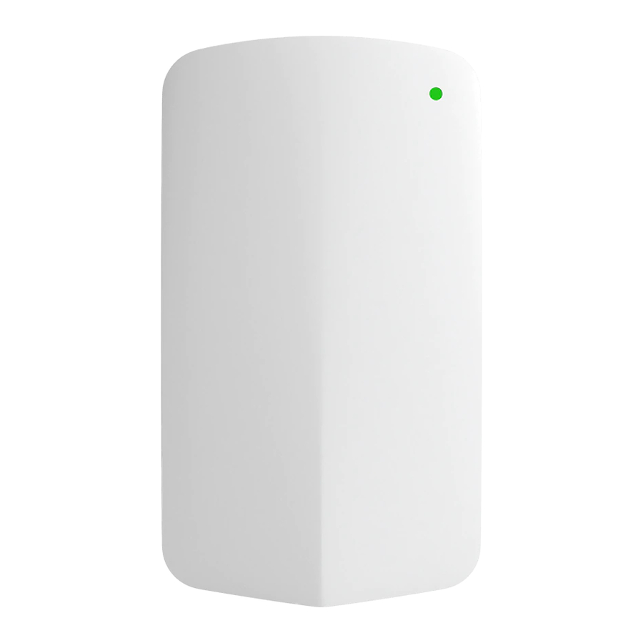
Product Overview
Physical Specifications
Dimensions
Power
Operating Environment
Hardware
117.1x65.7x23.3mm (LxWxH)
•
2xAA Alkaline Battery
•
Permanent DC Power: 5V;0.1A USB-C (Sold separately)
•
Temperature: 0°C - 55°C (32F - 131F)
•
Relative Humidity: 0 - 95 % RH
•
Multicolor, multifunction status LED
•
General purpose button
•
Reset button
•
USB-C port
1
Advertisement
Table of Contents

Related Manuals for Cisco MERAKI MT10


Summary of Contents for Cisco MERAKI MT10
- Page 1 Overview The Cisco Meraki MT10 a cloud managed Temperature and Humidity sensor that is exceptionally simple to configure and deploy due to its integration with the Meraki dashboard and the use of BLE technology. The MT family eliminates the complex and costly setup required by traditional solutions by removing the limitations of placement of these sensors.
- Page 2 General Purpose Button The MT10 has a general purpose button on the top which allows you to wake up the sensor and test if it is able to connect to a gateway. This will also upload the latest sensor data to the gateway.
-
Page 3: Package Contents
Configure Your Network in Dashboard The following is a brief overview only of the steps required to add an MT10 to your network. For detailed instructions about creating, configuring and managing Meraki Sensor networks, refer to the online documentation (https://documentation.meraki.com/MT). - Page 4 number of each sensor, which looks like Qxxx-xxxx-xxxx, and is found on the back of the unit or included in the box. 4. Add the gateway(MV or MR) to the same network as the sensor. NOTE: Make sure the gateway is in the same network and is online and operational. MV Set up Instructions MR Set up Instructions.
-
Page 5: Installation Instructions
MR 27.5.11 version will only show up on Organization that has at least 1 MT sensor claimed in a network. Installation Instructions Each MT10 comes with a Quick Install Guide within the box. This pamphlet contains detailed step by step guides and images to assist you in the physical installation of the sensors. -
Page 6: Testing The Connection
Magnet - Stick the magnet on any surface and the mounting plate can be stuck to the Magnet. Once the mounting plate is on the desired surface, slide the MT10 sensor onto the plate and use the included Torx screw to secure the sensor.
Need help?
Do you have a question about the MT10 and is the answer not in the manual?
Questions and answers