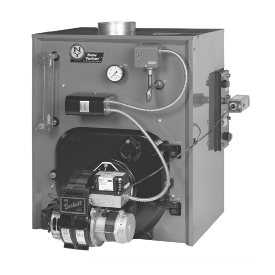
New Yorker CL Steam Series Installation, Operating And Service Instructions
Steam boiler natural draft, oil-fired
Hide thumbs
Also See for CL Steam Series:
Table of Contents
Advertisement
Installation, Operating and Service Instructions for
CL
TM
Steam
Models:
• CL3-105SET
• CL3-105SE
• CL3-140SET
• CL3-140SE
• CL4-168SET
• CL4-168SE
• CL4-210SET
• CL4-210SE
• CL5-245SET
• CL5-245SE
• CL5-266SET
• CL5-266SE
Manual Contents
1.
Product Description, Specification & . . . .
Dimensional Data . . . . . . . . . . . . . . . . . . . . 5
2. Pre-Installation . . . . . . . . . . . . . . . . . . . . . . 9
3. Steam Boiler Piping & Trim . . . . . . . . . . . 11
5. Venting . . . . . . . . . . . . . . . . . . . . . . . . . . . . 16
6. Electrical . . . . . . . . . . . . . . . . . . . . . . . . . . 17
7.
Oil Piping . . . . . . . . . . . . . . . . . . . . . . . . . . 20
8. System Start-up . . . . . . . . . . . . . . . . . . . . . 22
9. Operating . . . . . . . . . . . . . . . . . . . . . . . . . . 25
10. Maintenance & Service Instructions . . . . 27
11. Boiler Cleaning . . . . . . . . . . . . . . . . . . . . . 30
12. Troubleshooting . . . . . . . . . . . . . . . . . . . . 32
13. Service Parts . . . . . . . . . . . . . . . . . . . . . . . 34
14. Burner Specifications . . . . . . . . . . . . . . . . 40
Appendix . . . . . . . . . . . . . . . . . . . . . . . . . . 41
TO THE INSTALLER:
Affix these instructions adjacent to boiler.
TO THE CONSUMER:
Retain these instructions for future reference.
For service or repairs to boiler, call your heating contractor. When seeking information on boiler, provide
Boiler Model Number and Serial Number as shown on Rating Label.
110772-01 - 5/20
Page
• Steam Boiler
• Natural Draft
• Oil-Fired
9700609
Advertisement
Table of Contents

Related Manuals for New Yorker CL Steam Series


Summary of Contents for New Yorker CL Steam Series
-
Page 1: Table Of Contents
Installation, Operating and Service Instructions for • Steam Boiler • Natural Draft Steam • Oil-Fired Models: • CL3-105SET • CL3-105SE • CL3-140SET • CL3-140SE • CL4-168SET • CL4-168SE • CL4-210SET • CL4-210SE • CL5-245SET • CL5-245SE • CL5-266SET • CL5-266SE Manual Contents Page Product Description, Specification &... - Page 2 Installation & Service Manual IMPORTANT INFORMATION - READ CAREFULLY All boilers must be installed in accordance with National, State and Local Plumbing, All boilers must be installed in accordance with National, State and Local Plumbing, Heating and Electrical Codes and the regulations of the serving utilities. These Heating and Electrical Codes and the regulations of the serving utilities.
- Page 3 Installation & Service Manual DANGER DO NOT store or use gasoline or other flammable vapors or liquids in the vicinity of this or any other appliance. WARNING • Improper installation, adjustment, alteration, service or maintenance can cause property damage, personal injury or loss of life.
- Page 4 Installation & Service Manual WARNING • This boiler contains very hot water under high pressure. Do not unscrew any pipe fittings nor attempt to disconnect any components of this boiler without positively assuring the water is cool and has no pressure. Always wear protective clothing and equipment when installing, starting up or servicing this boiler to prevent scald injuries.
-
Page 5: Product Description, Specification
Installation & Service Manual Product Description, Specification and Dimensional Data The CL Series boiler is a cast iron oil-fired low The CL Series steam boiler uses a L404F pressure steam boiler designed for use in closed Pressure Limit and Low Water Cut-off. This boiler heating steam systems. - Page 6 Installation & Service Manual Product Description, Specification and Dimensional Data (continued) 110772-01 - 5/20...
-
Page 7: Pre-Installation
Installation & Service Manual Pre-Installation A. INSPECT SHIPMENT carefully for any signs of 3. FOR BASEMENT INSTALLATION, provide a damage. solid elevated base, such as concrete, if floor is not level, or if water may be encountered on 1. All equipment is carefully manufactured, floor around boiler. - Page 8 Installation & Service Manual Pre-Installation (continued) Direct communication with outdoors. NOTICE: Clearance to venting is for single wall Minimum free area of 1 square inch vent pipe. If Type L vent is used, clearance may per 4,000 BTU per hour input of all be reduced to the minimum required by the vent equipment in space.
-
Page 9: Steam Boiler Piping & Trim
Installation & Service Manual Steam Boiler Piping and Trim WARNING • Failure to properly pipe boiler may result in improper operation and damage to boiler or structure. • DO NOT increase steam boiler input above the ratings. • DO NOT use softened water in steam boilers. Accelerated boiler corrosion will result. Tie in fresh water supply to the boiler upstream of a water softener. - Page 10 Installation & Service Manual Steam Boiler Piping and Trim (continued) NOTICE Failure to pipe boiler as specified in this manual may result in excessive system noise, water line fluctuations and water carry over. 110772-01 - 5/20...
-
Page 11: Tankless & Indirect Water Heater Piping
Installation & Service Manual Tankless and Indirect Water Heater Piping A. CONNECT TANKLESS HEATER PIPING as CAUTION shown in Figure 4-1. See Table 4-2 for Tankless Use of hard water with a tankless coil will, over Heater Rating. a short period of time, reduce the output of the WARNING coil, reduce flow due to increased pressure Install automatic mixing valve at tankless heater... - Page 12 Installation & Service Manual Tankless and Indirect Water Heater Piping (continued) Figure 4-1: Schematic Tankless Heater Piping Table 4-2: Tankless Heater Data: Boiler Rating Pressure Drop Series (Gal/Min) (PSI) CL3-105SE-T 3.00 CL3-140SE-T 3.25 CL4-168SE-T 3.75 CL4-210SE-T 4.00 CL5-245SE-T 4.25 CL5-266SE-T 4.75 110772-01 - 5/20...
- Page 13 Installation & Service Manual Tankless and Indirect Water Heater Piping (continued) Figure 4-3: Indirect Domestic Water Heater Piping with V8H Steam Boiler B. CONNECT INDIRECT DOMESTIC WATER HEATER PIPING as shown in Figure 4-3. 1. Refer to Indirect Water Heater Installation, Operating, and Service Instructions for additional information.
-
Page 14: Venting
Installation & Service Manual Venting WARNING • Vent this boiler according to these instructions. Failure to do so may cause products of combustion to enter the home resulting in severe property damage, personal injury or death. • Insufficient Combustion Air Supply may result in the production and release of deadly carbon monoxide (CO) into the home which can cause severe personal injury or death. - Page 15 Installation & Service Manual Venting (continued) Figure 5-1: Recommended Vent Pipe Arrangement and Chimney Requirements Figure 5-2: Proper and Improper Locations of Draft Regulator 110772-01 - 5/20...
- Page 16 Installation & Service Manual Venting (continued) the canopy cannot be positive since this could d. Clean Chimney – Chimney shall be free of all create a condition that allows flue gas by-products loose debris. to escape from the draft regulator. A negative 5.
-
Page 17: Electrical
Installation & Service Manual Electrical DANGER Positively assure all electrical connections are unpowered before attempting installation or service of electrical components or connections of the boiler or building. Lock out all electrical boxes with padlock once power is turned off. WARNING •... - Page 18 Installation & Service Manual Electrical (continued) 110772-01 - 5/20...
- Page 19 Installation & Service Manual Electrical (continued) Figure 6-2: Schematic Wiring Diagrams For All Burner Options w/Various Oil Primary Controls 110772-01 - 5/20...
-
Page 20: Oil Piping
Installation & Service Manual Oil Piping A. GENERAL WARNING 1. Use flexible oil line(s) so the burner swing door Under no circumstances can copper with sweat can be opened without disconnecting the oil style connectors be used. supply piping. 2. A supply line fuel oil filter is recommended as a NOTICE Some jurisdictions require the use of a minimum for all firing rates but a pleated paper fusible shutoff valve at the tank and/or the burner. - Page 21 Installation & Service Manual Oil Piping (continued) C. TWO PIPE OIL LINES Table 7-3: Single-Stage Units (3450 RPM) - Two Pipe Systems 1. For two piped systems, where more lift is required, the two-stage fuel unit is Maximum Length of Tubing recommended.
-
Page 22: System Start-Up
Installation & Service Manual System Start-Up WARNING All boilers equipped with burner swing door have a potential hazard which can cause severe property damage, personal injury or loss of life if ignored. Before opening swing door, turn off service switch to boiler to prevent accidental firing of burner outside the combustion chamber. - Page 23 Installation & Service Manual System Start-Up (continued) c. To check the cutoff pressure, deadhead a H. CHECK FOR CLEAN CUT OFF OF reliable pressure gauge onto the copper BURNER. connector tube attached to the nozzle port. 1. AIR IN THE OIL LINE between fuel unit Run the burner for a short period of time.
- Page 24 Installation & Service Manual System Start-Up (continued) e. Check low water cut-off control with water level at normal water line (see Figure 1-1). Raise thermostat setting to allow burner to operate. Open boiler drain to allow water level to drop to bottom of sight glass until burner operation is shut-down by low water cut-off.
-
Page 25: Operating
Installation & Service Manual Operating A. STEAM BOILERS SEQUENCE OF OPERATION Upon a thermostat call for heat, when provided, the R8239A Control Center Relay or the Oil Primary Control is energized when the steam pressure is below the L404F Pressure Limit and water level is above the Low Water Cut-Off. - Page 26 Installation & Service Manual Operating (continued) Important Product Safety Information: Refractory Ceramic Fiber Product WARNING Some boiler components use materials that contain refractory ceramic fibers (RCF). RCF has been classified as a possible human carcinogen. When exposed to elevated temperatures, RCF may change into crystalline silica, a known carcinogen.
-
Page 27: Maintenance & Service Instructions
Installation & Service Manual Maintenance and Service Instructions A. MAINTENANCE OF LOW WATER CUT-OFF i. Apply a moderate amount of good quality DEVICES pipe dope to the pipe threads on the probe, leaving the two end threads bare. DO NOT WARNING use PTFE (Teflon) tape. - Page 28 Installation & Service Manual Maintenance and Service Instructions (continued) NOTICE Check with local authorities or consult iii. Turn on oil burner and keep operating local water treatment services for acceptable while feeding water to boiler slowly. This chemical cleaning compounds. will raise water level in boiler slowly so that water will be boiling hot and will iii.
- Page 29 Installation & Service Manual Maintenance and Service Instructions (continued) e. Make pH or Alkalinity Test. A leaky system will increase the volume of make-up water supplied to the boiler which can After boiler and system have been cleaned significantly shorten the life of the boiler. Entrained and refilled as previously described, test in make-up water are dissolved minerals, salts the pH of the water in the system.
-
Page 30: Boiler Cleaning
Installation & Service Manual Boiler Cleaning WARNING All boiler cleaning must be completed with burner service switch turned off. Boilers equipped with burner swing door have a potential hazard which can cause severe property damage, personal injury or loss of life if ignored. - Page 31 Installation & Service Manual Boiler Cleaning (continued) Figure 11-1: Cleaning of Boiler Flueways WARNING The boiler must be connected to an approved chimney in good condition. Serious property damage could result if the boiler is connected to a dirty or inadequate chimney. The interior of the chimney flue must be inspected and cleaned before the start of the heating season and should be inspected periodically throughout the heating season for any obstructions.
-
Page 32: Troubleshooting
Installation & Service Manual Troubleshooting A. COMBUSTION nozzle. The smaller the firing rate, the smaller the slots become in the nozzle and the more 1. NOZZLES — Although the nozzle is a relatively prone to plugging it becomes with the same inexpensive device, its function is critical to amount of dirt. - Page 33 Installation & Service Manual Troubleshooting (continued) e. Excessive back pressure causing flame to NOTICE CHECK TEST PROCEDURE. A very good test be erratic. for isolating fuel side problems is to disconnect the fuel system and with a 24" length of tubing, fire out of 3.
- Page 34 Installation & Service Manual This Page is Intentionally Blank. 110772-01 - 5/20...
-
Page 35: Service Parts
Installation & Service Manual Service Parts All CL™ Series repair parts may be ordered through New Yorker Boiler Company, Inc., or its authorized distributors. Should you require assistance in locating a New Yorker Distributor in your area, or have questions regarding the availability of New Yorker products or repair parts, please contact: New Yorker Boiler Company, Inc., P.O. - Page 36 Installation & Service Manual Service Parts (continued) 110772-01 - 5/20...
- Page 37 Installation & Service Manual Service Parts (continued) Item Description Part No. 1. BARE BOILER ASSEMBLY 110780-03 Block Assembly Carton for Steam, Rear Heater Operning Includes: Complete Block Assembly, Target Wall Insulation, Coil Gasket, 110780-04 Coil Cover Plaste/Hardware 110780-05 110781-03 Block Assembly for Steam, Non-Heater 110781-04 Includes: Complete Block Assembly, Target Wall Insulation 110781-05...
- Page 38 Installation & Service Manual Repair Parts (continued) 110772-01 - 5/20...
- Page 39 Installation & Service Manual Service Parts (continued) Item No. Description Part No. 101917-03 Complete Jacket Carton, Rear-Heater 101917-04 101917-05 101916-03 Complete Jacket Carton, Non-Heater 101916-04 101916-05 Pressure Gauge, 1/4" NPT x 2 1/2" Dia., 7/8" Lg. 109707-01 Honeywell PA404A1009 Pressuretrol w/ Syphon 110782-01 10-1/4"...
- Page 40 Installation & Service Manual Service Parts (continued) Item No. Description Part No. 110498-03 Beckett 110499-04 110500-05 110496-03 Carlin 110497-04 Shown 106862-01 Honeywell R7284P1080 103880-01 Beckett GeniSys Primary Control Obtain 7505p1515 Locally Carlin 110772-01 - 5/20...
-
Page 41: Burner Specifications
Installation & Service Manual Burner Specifications Table 14-1: Becket Settings Boiler Firing Rate Burner Pump Nozzle Shipped Head Model Model Pressure (Setting) Shutter Band CL3-105SE 0.75 0.65 x 60B (Hago) Installed Field CL3-140SE 1.00 0.85 x 60B (Hago) Provided CL4-168SE 1.20 1.00 x 60B (Hago) Installed... -
Page 42: Appendix
Installation & Service Manual Appendix - Aftermarket Low Water Cut Off (LWCO) WARNING DO NOT ATTEMPT to cut factory wires to install an aftermarket Low Water Cut Off (LWCO). Only use connections specifically identified for Low Water Cut Off. In all cases, follow the Low Water Cut Off (LWCO) manufacturer's instructions. Select the appropriate size tee using the LWCO When manufacturer’s instructions. - Page 43 Installation & Service Manual Appendix - Aftermarket Low Water Cut Off (LWCO) How to Test A 24 VAC LWCO is used primarily for gas fired Shut off fuel supply. Lower water level until water boilers where a 24 volt control circuit exists within level is BELOW the LWCO.
- Page 44 Installation & Service Manual New Yorker Boiler Company, Inc. P.O. Box 3005 Lancaster, Pennsylvania 17603-3005 Attn: Customer Service Department www.newyorkerboiler.com 110772-01 - 5/20...
Need help?
Do you have a question about the CL Steam Series and is the answer not in the manual?
Questions and answers