Juniper SSG 140 Hardware Installation And Configuration Manual
Hide thumbs
Also See for SSG 140:
- Product overview (7 pages) ,
- Hardware installation and configuration manual (60 pages) ,
- Manual (20 pages)

Subscribe to Our Youtube Channel
Related Manuals for Juniper SSG 140


Summary of Contents for Juniper SSG 140
- Page 1 Security Products SSG 140 Hardware Installation and Configuration Guide Juniper Networks, Inc. 1194 North Mathilda Avenue Sunnyvale, CA 94089 408-745-2000 www.juniper.net Part Number: 530-015643-01...
- Page 2 Copyright © 2006 Juniper Networks, Inc. All rights reserved. Juniper Networks and the Juniper Networks logo are registered trademarks of Juniper Networks, Inc. in the United States and other countries. All other trademarks, service marks, registered trademarks, or registered service marks in this document are the property of Juniper Networks or their respective owners.
-
Page 3: Table Of Contents
Connecting AC Power to the Device............... 22 Powering the Device On and Off..............22 Connecting the Device to a Network .............. 23 Connecting an SSG 140 Device to an Untrusted Network ......23 Connecting Ethernet Ports ..............24 Connecting Serial (AUX/Console) Ports..........24 Connecting PIMs.................. - Page 4 SSG 140 Series Hardware Installation and Configuration Guide Date and Time..................33 Administrative Access ................33 Management Services................33 Hostname and Domain Name ..............34 Domain Name System Server..............34 Default Route................... 35 Ethernet0/0 Interface IP Address ............. 35 PIM Configuration ..................35 ISDN Interface ..................
-
Page 5: About This Guide
(VPN) and firewall services for small- and medium-sized companies and enterprise branch and remote offices. The SSG 140 supports support universal serial bus (USB) storage and four physical interface modules (PIM) slots that can hold T1, E1, ISDN, and Serial wide area network (WAN) PIMs. -
Page 6: Organization
SSG 140 device. Chapter 2, “Installing and Connecting the Device” describes how to mount an SSG 140 device in a standard 19-inch equipment rack and how to connect cables and power to the device. Chapter 3, “Configuring the Device” describes how to configure and manage an SSG 140 device and how to perform some basic configuration tasks. -
Page 7: Cli Conventions
About This Guide Figure 1: Navigational Path and Configuration Settings CLI Conventions The following conventions are used to present the syntax of CLI commands in examples and in text. In examples: Anything inside square brackets [ ] is optional. Anything inside braces { } is required. If there is more than one choice, each choice is separated by a pipe ( | ). -
Page 8: Obtaining Documentation And Technical Support
SSG 140 Series Hardware Installation and Configuration Guide Obtaining Documentation and Technical Support To obtain technical documentation for any Juniper Networks product, visit www.juniper.net/techpubs/. For technical support, open a support case using the Case Manager link at http://www.juniper.net/support/ or call 1-888-314-JTAC (within the United States) or 1-408-745-9500 (outside the United States). -
Page 9: Chapter 1 Hardware Overview
Chapter 1 Hardware Overview This chapter provides detailed descriptions of the SSG 140 chassis and its components. It contains the following sections: “Port and Power Connectors” on page 10 “Front Panel” on page 11 “Back Panel” on page 15... -
Page 10: Port And Power Connectors
SSG 140 Series Hardware Installation and Configuration Guide Port and Power Connectors This section describes and displays the location of the built-in ports and power connector. Figure 2: Built-in Ports and Power Connector Locations Front TX/RX LINK TX/RX LINK TX/RX... -
Page 11: Front Panel
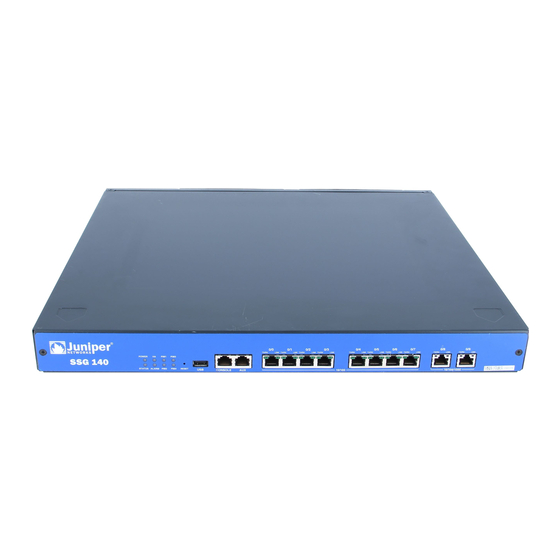
Front Panel This section describes the following elements on the front panel of an SSG 140 device: Device Status LEDs Port Descriptions Reset Pinhole USB Port Figure 3: SSG 140 Front Panel TX/RX LINK TX/RX LINK TX/RX LINK TX/RX LINK... -
Page 12: Port Descriptions
The ports are labeled 0/0 through 0/7. For the default zone bindings for each Ethernet port, see “Default Device Settings” on page 30. The SSG 140 device also has two 10/100/1000 Gigabit Ethernet ports (copper) to provide connectivity to Gigabit Ethernet LANs. The Gigabit ports are labeled 0/8 and 0/9. -
Page 13: Console Port
Figure 4: Ethernet port LEDs TX/RX LINK Table 3 describes the LAN port LEDs. Table 3: LAN Port LEDs Function Color State Description LINK Green On steadily Port is online Port is offline TX/RX Green Blinking Traffic is passing through. The data rate is proportional to the TX/RX activity Port might be on but is not receiving data Console Port... -
Page 14: Usb Port
SSG 140 Series Hardware Installation and Configuration Guide USB Port The USB port on the front panel of an SSG 140 device accepts a universal serial bus (USB) storage device or USB storage device adapter with a compact-flash disk installed, as defined in the CompactFlash Specification published by the CompactFlash Association. -
Page 15: Back Panel
These networks can be privately owned, but they more typically include public or shared networks. Table 4 describes the PIMs supported by the SSG 140 device. Table 5 describes the meaning of the PIM LED states. Table 4: SSG 140 PIMs... - Page 16 ISDN Synch Serial Table 6 lists the cables that you can order from Juniper Networks to connect to a port on the serial PIM. The device to which you are connecting and the serial interface type determine which cable you need.
-
Page 17: Power Switch
The power switch is located on the right side of the back panel, as shown in Figure 7. You use the power switch to power the SSG 140 device on and off. When you power on the device, ScreenOS boots up as the power supply completes its startup sequence. - Page 18 SSG 140 Series Hardware Installation and Configuration Guide Back Panel...
-
Page 19: Chapter 2 Installing And Connecting The Device
Chapter 2 Installing and Connecting the Device This chapter describes how to install an SSG 140 device in a standard 19-inch equipment rack and how to connect cables and power to the device. Topics in this chapter include: “Before You Begin” on page 20 “Equipment Installation”... -
Page 20: Before You Begin
Equipment Installation You can mount the SSG 140 device into a standard 19-inch equipment rack. If you are installing multiple devices in one rack, install the lowest one first and NOTE: proceed upward in the rack. - Page 21 Figure 8: Attaching the rack mount brackets 2. Grasp the sides of the device, lift the device, then position it in the rack. When correctly positioned, the device sits level in the equipment rack. 3. Align the bottom hole in each mounting bracket with a hole in each rack rail, making sure the chassis is level.
-
Page 22: Connecting Interface Cables To The Device
We recommend using a surge protector for the power connection. Powering the Device On and Off To power on the SSG 140 device, press the AC power switch on the rear panel to the on position. ScreenOS boots as the power supply completes its startup sequence. The Power LED lights during startup and remains on steadily when the device is operating normally. -
Page 23: Connecting The Device To A Network
Connecting an SSG 140 Device to an Untrusted Network Connecting the Device to an Internal Network or a Workstation Connecting an SSG 140 Device to an Untrusted Network You can connect your SSG 140 device to an untrusted network in one of the following ways: Connecting Ethernet Ports... -
Page 24: Connecting Ethernet Ports
Connecting Ethernet Ports To establish a high-speed connection, connect the provided Ethernet cable from the Ethernet port marked 0/0 on an SSG 140 device to the external router. The device autosenses the correct speed, duplex, and MDI/MDIX settings. Connecting Serial (AUX/Console) Ports You can connect to the untrusted network with an RJ-45 straight-through serial cable and an external modem. -
Page 25: Connecting The Device To An Internal Network Or A Workstation
You can connect your local area network (LAN) or workstation with the Ethernet interfaces. An SSG 140 device contains ten Ethernet ports. You can use one or more of these ports to connect to LANs through switches or hubs. You can also connect one or all of the ports directly to workstations, eliminating the need for a hub or switch. - Page 26 SSG 140 Series Hardware Installation and Configuration Guide Connecting the Device to a Network...
-
Page 27: Chapter 3 Configuring The Device
Chapter 3 Configuring the Device ScreenOS software is preinstalled on the SSG 140 device. When the device is powered on, it is ready to be configured. While the device has a default factory configuration that allows you to initially connect to the device, you need to perform further configuration for your specific network requirements. -
Page 28: Accessing The Device
NetScreen-Security Manager: NetScreen-Security Manager is a Juniper Networks enterprise-level management application that enables you to control and manage Juniper Networks firewall/IPSec VPN devices. For instructions on how to manage your device with NetScreen-Security Manager, refer to the NetScreen-Security Manager Administrator’s Guide. -
Page 29: Using The Webui
2. Plug the male end of the RJ-45 CAT5 serial cable into the Console port on the SSG 140. (Be sure that the other end of the CAT5 cable is inserted properly and secured in the DB-9 adapter.) 3. Launch a serial terminal-emulation program on your workstation. The required... -
Page 30: Using Telnet
10 minutes of idle time. To remove the timeout, enter set console timeout 0 . Default Device Settings This section describes the default settings and operation of an SSG 140 device. Table 7 describes the default zone bindings for ports on the device. - Page 31 Note that the ethernet0/0 interface has the default IP address 192.168.1.1/24 and is configured for management services. If you connect the 0/0 port on the SSG 140 device to a workstation, you can configure the device from a workstation in the 192.168.1.1/24 subnetwork using a management service such as Telnet.
-
Page 32: Basic Device Configuration
This section describes the basic configurations that you need to perform to allow the SSG 140 device to connect LAN users to a remote network. For more detailed information about ScreenOS features and how to configure them, see the Concepts &... -
Page 33: Date And Time
Date and Time The time set on an SSG 140 device affects events such as the setup of VPN tunnels. The easiest way to set the date and time on the device is to use the WebUI to synchronize the device system clock with the workstation clock. -
Page 34: Hostname And Domain Name
Domain Name System Server The Domain Name System (DNS) server on the network maintains a database for resolving hostnames and IP addresses. The SSG 140 device accesses the configured DNS servers to resolve hostnames. In ScreenOS, you configure the IP addresses for the primary and secondary DNS servers and the time of the day at which the device performs a DNS refresh. -
Page 35: Default Route
Default Route The default route is a static route used to direct packets addressed to networks that are not explicitly listed in the routing table. If a packet arrives at the device with an address for which the device does not have routing information, the device sends the packet to the destination specified by the default route. -
Page 36: Isdn Interface
SSG 140 Series Hardware Installation and Configuration Guide ISDN Interface Integrated Services Digital Network (ISDN) is a set of standards for digital transmission over different media created by the Consultative Committee for International Telegraphy and Telephone (CCITT) and International Telecommunications Union (ITU). As a dial-on-demand service, it has fast call setup and low latency as well as the ability to carry high-quality voice, data, and video transmissions. -
Page 37: E1 Interface
“junipertest” static-ip set ppp profile “junipertest” auth type chap set ppp profile “junipertest” auth local-name “juniper” set ppp profile “junipertest” auth secret “password” set interface serial1/0 ppp profile “junipertest” set interface serial1/0 ip 172.18.1.1/24... -
Page 38: Serial Wan Interface
A serial cable connects the DCE to a telephony network where, ultimately, a link is established with data terminal equipment (DTE). DTE is typically where a link terminates. SSG 140 series serial WAN PIMs support the following serial standards: TIA/EIA 530 V.35 X.21... -
Page 39: Basic Firewall Protections
Concepts & Examples ScreenOS Reference Guide. The SSG 140 device provides various detection methods and defense mechanisms to combat probes and attacks aimed at compromising or harming a network or network resource: ScreenOS SCREEN options secure a zone by inspecting, and then allowing or denying, all connection attempts that require crossing an interface to that zone. -
Page 40: Verifying External Connectivity
SSG 140 Series Hardware Installation and Configuration Guide Verifying External Connectivity To verify that workstations in your network can access resources on the Internet, start a browser from any workstation in the network and enter the following URL: www.juniper.net. Resetting the Device to Factory Defaults If you lose the admin password, you can reset the device to its default settings. - Page 41 After the device has rebooted, the console displays the login prompt for the device. The STATUS LED blinks green. The login for the admin name and password is netscreen. If you do not follow the complete sequence, the reset process cancels without any configuration change and the console message states that the erasure of the configuration is aborted.
- Page 42 SSG 140 Series Hardware Installation and Configuration Guide Resetting the Device to Factory Defaults...
-
Page 43: Chapter 4 Servicing The Device
Tools and Parts Required To replace a component on an SSG 140 device, you need the following tools and parts: Electrostatic bag or antistatic mat... -
Page 44: Replacing A Physical Interface Module
SSG 140 Series Hardware Installation and Configuration Guide Replacing a Physical Interface Module The SSG 140 device has four slots in the back panel for WAN PIMs. SSG 140 PIMs are field installable and replaceable. The SSG 140 device must be powered off before PIMs are removed or installed. -
Page 45: Installing A Physical Interface Module
6. If necessary, arrange the cables to prevent them from dislodging or developing stress points: Secure the cable so that it is not supporting its own weight as it hangs to the floor. Place excess cable out of the way in a neatly coiled loop. Use fasteners to maintain the shape of cable loops. -
Page 46: Upgrading Memory
8. Verify that the PIM status LED lights steadily green to confirm that the PIM is online. Upgrading Memory You can upgrade an SSG 140 device that has 256 MB of memory to 512 MB by replacing the 256 MB memory module with a 512 MB memory module. Ask your Juniper reseller for kit SSG-100-MEM-512. - Page 47 2. Power off the device. Verify that the POWER LED turns off. 3. Remove the device from its rack mount. 4. Use a number-2 phillips screwdriver to remove the screws securing the rack mount brackets to the sides of the unit (four screws per side). 5.
-
Page 48: Replacing The Fuse
17. Replace the SSG 140 in the equipment rack. Replacing the Fuse The SSG 140 device uses a 6.3 Amp fast acting fuse rated for 250 Volts. To replace a failed fuse on the SSG 140 device, perform the following steps: 1. - Page 49 Figure 16: Removing the Fuse 3. Manually remove the fuse assembly from the device. 4. To replace the fuse assembly, enter the new fuse into the opening and slide it in until the fuse clicks into place. 5. Replace the power cable and turn the device power switch ON. Reconnect the network cables.
- Page 50 SSG 140 Series Hardware Installation and Configuration Guide Replacing the Fuse...
-
Page 51: Appendix A Specifications
Appendix A Specifications This appendix provides general specifications for the SSG 140 device. It contains the following sections: “SSG 140 Physical Specifications” on page 52 “Electrical Specifications” on page 52 “Environmental Tolerance” on page 52 “Certifications” on page 52 “Connectors” on page 54... -
Page 52: Ssg 140 Physical Specifications
SSG 140 Series Hardware Installation and Configuration Guide SSG 140 Physical Specifications Table 8: SSG 140 Physical Specifications Description Value Chassis 1.75 inches (4.4 cm) high dimensions 17.5 inches (44.4 cm) wide—18.9 in. (48 cm) wide with mounting brackets attached 15 inches (38.1 cm) deep—plus 0.5 in. -
Page 53: Emc Emissions
EMC Emissions FCC Part 15 Class B (USA) EN 55022 Class B (Europe, Australia, New Zealand) VCCI Class B (Japan) BSMI Class B (Taiwan) EMC Immunity EN 55024 EN-61000-3-2 Power Line Harmonics EN-61000-3-3 Voltage Fluctuations and Flicker EN-61000-4-2 ESD EN-61000-4-3 Radiated Immunity EN-61000-4-4 EFT EN-61000-4-5 Surge Certifications... -
Page 54: European Telecommunications Standards Institute
SSG 140 Series Hardware Installation and Configuration Guide EN-61000-4-6 Low Frequency Common Immunity EN-61000-4-11 Voltage Dips and Sags European Telecommunications Standards Institute European Telecommunications Standards Institute (ETSI) EN-300386-2: Telecommunication Network Equipment. Electromagnetic Compatibility Requirements (equipment category other than telecommunication centers) -
Page 55: Appendix B Initial Configuration Wizard
Initial Configuration Wizard This appendix provides detailed information about the Initial Configuration Wizard (ICW) for an SSG 140 device. After you have physically connected your device to the network, you can use the ICW to configure the interfaces that are installed on your device. -
Page 56: Rapid Deployment Window
SSG 140 Series Hardware Installation and Configuration Guide 1. Rapid Deployment Window Figure 17: Rapid Deployment Window If your network uses NetScreen-Security Manager, you can use a Rapid Deployment configlet to automatically configure the device. Obtain a configlet from your Security Manager administrator, select the Yes option, select the Load Configlet from: option, browse to the file location, then click Next. -
Page 57: Physical Ethernet Interface Window
3. Physical Ethernet Interface Window On the interface-to-zone bindings screen, you set the interface to which you want to bind the Untrust security zone. Ethernet0/0 is prebound to the Trust security zone. Ethernet0/1 is bound to the DMZ security zone but is optional. Ethernet0/2 is bound to the Untrust zone. -
Page 58: Other Interface Ip Address Window
SSG 140 Series Hardware Installation and Configuration Guide Table 12: Field Descriptions for Ethernet0/0 Interface Field Description Dynamic IP via DHCP Enables the device to receive an IP address for the Untrust zone interface from an ISP. Dynamic IP via PPPoE Enables the device to act as a PPPoE client, receiving an IP address for the Untrust zone interface from an ISP. -
Page 59: Physical Ethernet Dhcp Interface Window
6. Physical Ethernet DHCP Interface Window Select Yes to enable your device to assign IP addresses to your wired network via DHCP. Enter the IP address range that you want your device to assign to clients using your network, then click Next. Figure 22: Ethernet0/0 Interface Window... -
Page 60: Confirmation Window
SSG 140 Series Hardware Installation and Configuration Guide 7. Confirmation Window Confirm your device configuration and change as needed. Click Next to save, reboot the device, and run the configuration. Figure 23: Confirmation Window After the device reboots with the saved system configuration, the WebUI login prompt appears. -
Page 61: Index
............20 administrative access ..........33 installing a PIM ...............45 basic ................32 date and time ............33 default route .............35 Juniper serial cables ............16 DNS server ...............34 E1 PIM ..............37 ethernet0/0 IP address ...........35 LAN port LEDs ..............13 host and domain name ..........34 LED dashboard ...............11... - Page 62 SSG 500 Series Hardware Installation and Configuration Guide power switch ..............17 removing a PIM ............. 44 removing faceplate ............44 replacing PIMs ............... 44 reset pinhole, using ............40 safety certifications ............52 serial cables ..............16 status LED ..............
Need help?
Do you have a question about the SSG 140 and is the answer not in the manual?
Questions and answers