Table of Contents
Advertisement
Advertisement
Table of Contents

Related Manuals for Trend Micro TippingPoint NX-Platform

Summary of Contents for Trend Micro TippingPoint NX-Platform
- Page 1 NX-Platform Hardware Installation and Safety 5998-1403 October 2016...
- Page 2 This document contains confidential information, trade secrets or both, which are the property of Trend Micro Incorporated. No part of this documentation may be reproduced in any form or by any means or used to make any derivative work (such as translation, transformation, or adaptation) without written permission from Trend Micro Incorporated or one of its subsidiaries.
-
Page 3: Table Of Contents
Contents About this guide............................1 Target audience............................1 Related documentation...........................1 Conventions............................1 Contacting support..........................3 System overview............................. 4 TippingPoint architecture........................4 Security Management System (SMS)....................5 SMS server............................6 SMS client............................6 Intrusion Prevention System devices..................... 7 IPS local clients........................... 8 Core Controller............................8 High availability............................9 Threat Suppression Engine........................9 Threat Management Center......................... - Page 4 Ventilation and location........................16 Environmental requirements.........................16 Reliable earthing...........................17 ESD requirements..........................17 Hot swapping guidelines........................17 Unpack the product..........................18 TippingPoint NX-Platform device overview..................20 Chassis overview..........................20 Chassis features..........................23 Power button........................... 23 Fans and power supplies........................24 External storage card........................24 Ports..............................24...
- Page 5 Technical specifications........................36 Hardware and interface specifications....................36 Software specifications........................37 Hardware installation and configuration....................38 TippingPoint NX-Platform IPS chassis....................38 Determine total rack space......................38 Attach the device to the rack......................39 Rack-mounting options......................... 39 Power supply and I/O module connections..................41 Add I/O modules..........................
- Page 6 About the external storage card......................54 External storage card commands......................54 Connector and pinout specifications....................56 RJ-45 (COM) console...........................56 RJ-45 Ethernet connectors........................57 Pluggable transceivers......................... 58 NX-Platform Hardware Installation and Safety...
-
Page 7: About This Guide
About this guide Welcome to the NX-Platform Hardware Installation and Safety Guide. This section covers the following topics: • Target audience on page 1 • Related documentation on page 1 • Conventions on page 1 Contacting support • on page 3 Target audience The intended audience includes technicians and maintenance personnel responsible for installing, configuring, and maintaining TippingPoint security systems and associated devices. - Page 8 Typefaces TippingPoint uses the following typographic conventions for structuring information: Convention Element Bold font • Key names • Text typed into a GUI element, such as into a box • GUI elements that are clicked or selected, such as menu and list items, buttons, and check boxes.
-
Page 9: Contacting Support
Tip: Provides helpful hints and shortcuts, such as suggestions about how to perform a task more easily or more efficiently. Contacting support Contact the TippingPoint Technical Assistance Center (TAC) by using any of the following options. Email support tippingpoint.support@trendmicro.com Phone support North America: +1 866 681 8324 International: See https://tmc.tippingpoint.com... -
Page 10: System Overview
System overview The TippingPoint system is a high-speed, comprehensive security system that includes the Intrusion Prevention System (IPS), Local Security Manager (LSM), Digital Vaccine, the Security Management System Appliance, and the Core Controller. Enterprise security schemes once consisted of a conglomeration of disparate, static devices from multiple vendors. -
Page 11: Security Management System (Sms)
Figure 1. TippingPoint architecture Security Management System (SMS) Describes the core components of the SMS. The SMS core components include: SMS Secure Server —hardware appliance for managing multiple devices • • SMS Home Page — web-based interface with links to current client software, documentation, and the Threat Management Center •... -
Page 12: Sms Server
• Digital Vaccine (DV) — Update service that includes up-to-date filter packages for protecting your network. • Managed Devices — TippingPoint IPS or Core Controller devices that are installed in your network. SMS server The SMS Server is an enterprise-class management platform that provides centralized administration, configuration, monitoring and reporting for well over a hundred TippingPoint IPS devices. -
Page 13: Intrusion Prevention System Devices
• Windows XP • Windows 7 • Apple OS X • Red Hat Linux • One of the following browsers: • Microsoft Internet Explorer, version 6.0 or higher • Firefox • Safari The SMS features a policy-based operational model for scalable and uniform enterprise management. It enables behavior and performance analysis with trending reports, correlation and real-time graphs. -
Page 14: Ips Local Clients
TippingPoint Intrusion Prevention Systems are optimized to provide high resiliency, and high-availability security for remote branch offices, small-to-medium and large enterprises and collocation facilities. Each IPS can protect network segments from both external and internal attacks. Multiple TippingPoint devices can be deployed to extend this unsurpassed protection to hundreds of enterprise zones. -
Page 15: High Availability
Note: The Core Controller can be used with the 2400E and 5000E IPS devices, and with all N-Platform and NX-Platform devices. High availability TippingPoint devices are designed to guarantee that your network traffic always flows at wire speeds in the event of internal device failure. -
Page 16: Threat Management Center
• Application-layer parsing of over 170 network protocols The TSE reconstructs and inspects flow payloads by parsing the traffic at the application layer. As each new packet of the traffic flow arrives, the engine re-evaluates the traffic for malicious content. The instant the engine detects malicious traffic, it blocks all current and all subsequent packets pertaining to the traffic flow. - Page 17 • Traffic Management filters — Protect the network by shielding against IP addresses or permitting only a set of IP addresses. NX-Platform Hardware Installation and Safety...
-
Page 18: Hardware Safety And Compliance
Hardware safety and compliance This topic describes TippingPoint product regulatory compliance and provides safety requirements and warnings. Before installing your TippingPoint product, you must read through all preparation instructions and safety requirements. • Safety and compliance requirements on page 12 •... -
Page 19: Cautions
• This product has serviceable modules and hot-swappable power supplies. It has no other serviceable parts inside. Cautions Cautions tell you how to avoid a serious loss that stops short of physical damage such as the loss of data, time, or security. Cautions tell you what you should or should not do to avoid such losses, and the consequences of not heeding the caution. -
Page 20: Parts Warnings
Warning! When installing the product, always make the ground connection before applying power to the unit. This equipment needs to be grounded to an external ground connection. Use a green and yellow 12 AWG ground wire to connect the host to earth ground during normal use. Disconnect the ground connection only when the unit is completely powered down. -
Page 21: Rack And Clearance Requirements
flow of cooling air through the chassis. To prevent electric shock, do not open the enclosure of the product. Warning! To reduce the risk of fire, use only No. 26 AWG or larger telecommunication line cord. Warning! Risk of explosion if battery is replaced by an incorrect type. Dispose of used batteries according to the instructions. -
Page 22: Ventilation And Location
The vertical hole spacing on the rack rails must meet standard EIA-310-C requirements, which call for a one inch (2.54 cm) spacing. Ensure that you have a minimum of three inches clearance at the side of the ventilation slots. Note: Some devices have different rack and clearance requirements, or may have other mounting and installation options. -
Page 23: Reliable Earthing
Reliable earthing Ensure that an external grounding connection is available for the product. Follow these guidelines: • For AC-powered products, use only the AC power cords that have been provided with the product. Using other cords could be hazardous to your safety. •... -
Page 24: Unpack The Product
Some TippingPoint devices allow you to hot swap cards or modules. The TippingPoint has a comprehensive detection system that senses automatically when you add or remove a card or module. It then runs diagnostic and discovery routines and acknowledges the presence or absence of the card. If you remove a card or module and replace it with the same type of card or module, the system resumes operation without any operator intervention. - Page 25 7. Inspect all the equipment inside for damage. If you think any equipment might be damaged, contact your freight provider for how to lodge a damage claim. Also, contact your TippingPoint sales or field representative for instructions. Note: The shipping materials are recyclable. Please save for later use or dispose of them appropriately. NX-Platform Hardware Installation and Safety...
-
Page 26: Tippingpoint Nx-Platform Device Overview
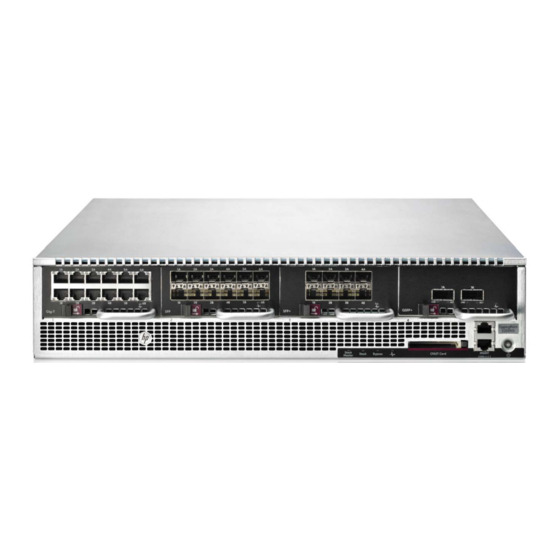
TippingPoint NX-Platform device overview This topic describes the components, chassis, requirements, and installation of the TippingPoint S2600 NX/ S5200 NX/S6200 NX/S7100 NX/S7500 NX devices and their components. These devices are associated with the following part numbers: Model HPE part number Trend Micro part number TippingPoint S2600 NX JC874A TPNN0026 TippingPoint S5200 NX... - Page 27 The following traffic throughputs are supported across multiple copper and fiber segments for each model: Model Supported throughput TippingPoint S2600 NX Up to 3Gbps TippingPoint S5200 NX Up to 5Gbps TippingPoint S6200 NX Up to 10Gbps TippingPoint S7100 NX Up to 15Gbps TippingPoint S7500 NX Up to 20Gbps Figure 2. TippingPoint NX-Platform IPS - front panel, no modules installed 1.
- Page 28 Figure 3. TippingPoint NX-Platform IPS - front panel, modules installed 1. 6-Segment Gig-T NX module 2. 6-Segment GbE SFP NX module 3. 4-Segment 10GbE SFP+ NX module 4. 1-Segment 40GbE QSFP+ NX module 5. Stack Master LED 6. Stack LED 7. Bypass LED 8.
-
Page 29: Chassis Features
1. Ground strap mounting 2. Power supply health LED 3. Power supply module 1 4. Power supply module 2 5. Fan module 1 6. Fan module 2 7. Fan module 3 8. Fan module 4 9. Fan module 5 Chassis features Provides links to the various NX-Platform chassis features. -
Page 30: Fans And Power Supplies
• Green — Device is powered on. Fans and power supplies The TippingPoint NX-Platform IPS includes two power supplies and five cooling fans. Power supply and fan modules on page 46. External storage card The TippingPoint NX-Platform IPS includes a CFast card slot. The external storage card is used to store system logs, snapshots, and other system data. -
Page 31: Chassis Leds
1. RJ-45 serial console port 2. 1GbE copper management port 3. Link LED 4. Activity LED The management port LEDs indicate link and activity state: LED type Color Description Link Green Link is active at 1000 Mbps. Link is inactive, or is active at 10 Mbps or 100 Mbps. -
Page 32: I/O Modules
Port type Color Description Yellow Unit failed to join a stack. Blinking yellow Unit is in process of joining a stack. Blinking green Blink pattern indicates stack ID. Bypass The system is not in Layer-2 Fallback (L2FB). The system is in L2FB. System Health Solid green The system health is OK. - Page 33 Important: Hot-swapping a 40GbE I/O module with another 40GbE I/O module is fully supported. However, a full reboot is required under the following conditions: • If you insert a 40GbE module into a slot which previously did not have a 40GbE module •...
- Page 34 Module name Ports Port speed Part number 1-Segment 40GbE QSFP+ NX (QSFP+) 2 Fiber 40Gbps TPNN0069 Note: If you insert an SFP into a 10GbE module slot, the port might go down. To use an SFP in a 10GbE module, configure the slot by entering the following command in the command line interface: conf term interface ethernet 1-1A negotiate conf term interface ethernet 1-1A no negotiate conf term interface ethernet 1-1A linespeed 1000...
-
Page 35: Bypass I/O Modules
Module name Ports Port speed Part number NX IPS 2-Segment 1GbE Fiber SR Bypass Module 4 Multi- 1Gbps TPNN0071 Mode Fiber (LC type) NX IPS 2-Segment 1GbE Fiber LR Bypass Module 4 Single- 1Gbps TPNN0072 Mode Fiber (LC type) NX IPS 2-Segment 10GbE Fiber SR Bypass Module 4 Multi- 1/10Gbps TPNN0073... -
Page 36: Biom Connectors And Speeds
Note: When you hot-insert a BIOM, it remains in bypass mode until an administrator removes it from bypass mode through the CLI, LSM, or SMS. Rebooting the IPS after a hot-insertion also brings the module into normal (non-bypass) mode. After the system has fully rebooted, it is ready for inspection. -
Page 37: Link Transitions
between equipment A and B is 100 meters, then the cable length between equipment A and BIOM-1A plus equipment B and BIOM-1B cannot exceed 100 meters. Warning! BIOMs use internal mechanical switches that are highly sensitive. Use care when removing the module from the IPS while the network is still connected to the segment ports. -
Page 38: Default I/O Module Configuration Settings
multimode multimode Nominal Worst case Nominal Worst case Switch loss 0.6dB 1.0dB 0.7dB 1.0dB Total module insertion loss 0.8dB 2.0dB 0.9dB 1.9dB Default I/O module configuration settings Describes the default I/O module settings. Configurations for the I/O modules can be changed after they are set to the defaults values. However, the default settings themselves cannot be changed. -
Page 39: I/O Module Hot-Swapping Guidelines
I/O modules are hot-swappable. As long as the IPS is running TOS v3.6.0 or higher, I/O modules can be inserted, removed, or replaced while the IPS is operational. I/O modules in other slots are not impacted, and the IPS continues to function and inspect traffic. Note: Hot-swapping I/O modules during system initialization is not supported. -
Page 40: Module Leds
• The following conditions are displayed when the corresponding ports and segments are available, and are hidden when they are unavailable: • Segment configuration • Network port configuration • Network port health • Network port throughput performance • Traffic profile by network port •... -
Page 41: Model Requirements
Feature Color Description Activity Amber Data traffic passing. Module Status Green The module is configured, in service, and Health in good health. Blinking The module has been inserted and amber powered up, but is not yet recognized by the software. Solid amber The module is experiencing a fault. -
Page 42: Cabling Requirements
The device’s maximum power consumption is 750 W. Warning! This product requires short-circuit (overcurrent) protection, to be provided as part of the building installation. Install only in accordance with national and local wiring regulations. The TippingPoint NX-Platform IPS power supply modules are hot-swappable. Refer to the installation instructions that shipped with your replacement power supply module for information about hot-swapping modules. -
Page 43: Software Specifications
Specification Description Dimensions 2RU - 3.41 in x 16.84 in x 22 in (8.67 cm x 42.78 cm x 55.88 cm) Weight 42 lbs (19.05 kg) Power Requirements • AC: Voltage 100 – 240; Current 12 – 6; Frequency 50/60 Hz •... -
Page 44: Hardware Installation And Configuration
Prior to installation, you should also obtain the IPS Command Line Interface Reference. After installation of the components, run through the OBE Setup Wizard as part of the installation and configuration procedures. This topic includes the following information: TippingPoint NX-Platform IPS chassis • on page 38 •... -
Page 45: Attach The Device To The Rack
Attach the device to the rack Describes how to load the device onto the rack. The IPS ships with a slide rail kit to mount the device to the rack. Slide rail kits are also separately available for order from TippingPoint. Refer to the instructions in the slide rail kit for information about installing the slide rails. - Page 46 • For extra support against seismic vibrations, you can secure an additional bracket to each of the rack- mounting ears. The seismic brackets accommodate two-post racks that are 5 – 6 inches deep. After securing the chassis to the rack with the standard rack-mounting ears, loosely mount the seismic brackets into the holes of the rack-mounting ears with the provided SEMS screws (four on each side, included).
-
Page 47: Power Supply And I/O Module Connections
• For mid-mounting, reverse the two rack-mounting ears and secure them to the chassis using the flat- head screws (six on each side) that came with the kit, as shown in the following figure. Fasten the rack- mounting ears to the rear rack post with screws (six on each side, not included). Figure 8. -
Page 48: Add I/O Modules
your device running. Refer to Hot-swapping I/O modules on page 32 for more information on installing modules with the IPS running. Note: Hot-swapping I/O modules during system initialization is not supported. To turn the power on, use the power button located on the front panel of the device. The TippingPoint NX-Platform IPS comes with a power cord retention bracket and a cable management assembly. -
Page 49: Attach Cables
To insert an I/O module, slide the module into the empty module slot. When the module is in the correct position, the slide latch automatically slides into position. Important: Handle all I/O modules with care. The bypass modules contain mechanical switches that are very sensitive to handling when not installed in the system. -
Page 50: To Attach The Console Port Connection
To attach the Console port connection Describes how to attach the console port connection. 1. Connect the RJ-45 null modem cable to the Console port on the unit. 2. Connect the other end of your cable (standard-sized female DB-9 connector) to your VT100-compatible terminal or your computer. -
Page 51: Setup Wizard
Setup wizard After you have powered on, the TippingPoint Setup wizard is displayed on your COM port terminal. The wizard prompts you to perform basic configuration tasks and periodically input information. After you run the setup, you can further configure your system using subsequent setup commands through the Command Line Interface (CLI). -
Page 52: Power Supply And Fan Modules
Power supply and fan modules This topic provides links to installation instructions for power supply modules and fans. The following subjects are discussed. • NX-Platform AC power supply on page 46 • NX-Platform DC power supply on page 47 • NX-Platform fans on page 49 Warning! This product might have more than one power supply source. -
Page 53: Nx-Platform Dc Power Supply
1. Removal latch 2. Handle 3. Status LED 4. AC male power input The Status LED is green when the module is powered and running normally. When the AC power supply has been securely placed in the device, use the following procedure to connect power to the AC power supply: 1. - Page 54 Caution: Do not attach a ground wire to the ground screw on the DC power supply module. Attach the ground wire to the NX-Platform chassis DC grounding screw holes (0.63-inch hole spacing) with #10 screws. The DC grounding screw holes are located in the rear of the NX- Platform chassis.
-
Page 55: Nx-Platform Fans
The NX-Platform devices include five cooling fans. The fans are redundant and hot-pluggable, and can be replaced without powering down the device. The IPS NX-Platform Spare Fan (part number TPNN0084) is a replacement unit and can only be used with TippingPoint NX-Platform devices. Figure 14. NX Series fan 1. Removal Latch 2. - Page 56 4. Install the new fan assembly by sliding the fan into the open slot. The latch slides into place automatically. After you insert the fan module, the fan LED blinks for up to two minutes while the system verifies the fan RPM.
-
Page 57: Installing The Power Cord Retention Bracket
Installing the power cord retention bracket This topic provides links to topics with installation instructions for the power cord retention bracket. The following subjects are discussed: • Power cord retention bracket on page 51 • Installing and using the bracket on page 51 •... -
Page 58: Installing The Bracket
Figure 16. TippingPoint NX-Platform IPS - back panel 1. Ground Strap Mounting 2. Power Cord Bracket Follow the procedures in this topic to install and use the power cord retention bracket and the cable management bracket. Installing the bracket Describes how to install the bracket. -
Page 59: Removing The Bracket
Removing the bracket If you need to remove one of the brackets, pull the spring-loaded plunger in the middle of the bracket and slide the bracket up and off the shoulder rivets. NX-Platform Hardware Installation and Safety... -
Page 60: Using The External Storage Card
Using the external storage card This topic provides links to topics with external storage card information. The following subjects are discussed: • About the external storage card on page 54 • External storage card commands on page 54 About the external storage card The external storage card is used to store system logs, snapshots, and other system data. - Page 61 Command Description conf t compact-flash Sets the device to automatically mount cards when inserted. operation-mode auto-mount show compact-flash Displays whether the card is mounted, and if so, its model number, serial number, revision number, capacity, operation mode, and mount status. show conf compact-flash Shows the card’s operation mode.
-
Page 62: Connector And Pinout Specifications
Connector and pinout specifications This topic provides links to topics with connector and pinout information for the TippingPoint system. This topic contains the following information: • RJ-45 (COM) console on page 56 • RJ-45 Ethernet connectors on page 57 • Pluggable transceivers on page 58 RJ-45 (COM) console... -
Page 63: Rj-45 Ethernet Connectors
Pin number Signal name Data Set Ready (DSR) Clear to Send (CTS) RJ-45 Ethernet connectors Describes how to use the RJ-45 connector under different operating conditions. Use the following pinout information when your RJ-45 device is operating in 10Mbps/100Mbps mode. Pin number Signal name Transmit positive (Tx+) -
Page 64: Pluggable Transceivers
Pin number Signal name Twisted Pair 1 positive (TP1+) Twisted Pair 1 negative (TP1-) Twisted Pair 2 positive (TP2+) Twisted Pair 3 positive (TP3+) Twisted Pair 3 negative (TP3-) Twisted Pair 2 negative (TP2-) Twisted Pair 4 positive (TP4+) Twisted Pair 4 negative (TP4-) Pluggable transceivers The IPS can also have pluggable transceivers. - Page 65 Fiber input Signal Left side Transmit Right side Receive NX-Platform Hardware Installation and Safety...
Need help?
Do you have a question about the TippingPoint NX-Platform and is the answer not in the manual?
Questions and answers