Table of Contents
Advertisement
Quick Links
For More Information:
For more information on this product and all of the products and services provided by
www.lantronix.com
Lantronix, please visit us at
us directly at any of our corporate and regional headquarters. A complete listing of all our
sales offices can be found at our web site.
Corporate Offices
Europe, Middle East & Africa (EMEA)
15353 Barranca Parkway
Minervum 1707
Irvine, CA 92618
4817 ZK Breda
USA
The Netherlands
949 453 3990
+31 (0) 76 565 8176
949 453 3995 fax
+31 (0) 76 565 8179 fax
sales@lantronix.com
eu_sales@lantronix.com
. For immediate needs, you may contact
Pacific Rim
46 East Coast Road
East Gate #10-01
Singapore 428766
+65 447 4222
+65 344 0614 fax
asiapacsales@lantronix.com
Part Number: 900-193
Device Servers
Installation
Guide
Advertisement
Table of Contents
Troubleshooting

Subscribe to Our Youtube Channel
Related Manuals for Lantronix MSS100


Summary of Contents for Lantronix MSS100
- Page 1 For more information on this product and all of the products and services provided by www.lantronix.com Lantronix, please visit us at . For immediate needs, you may contact us directly at any of our corporate and regional headquarters. A complete listing of all our sales offices can be found at our web site.
- Page 2 MSS Installation Guide For MSS100 Device Servers...
- Page 3 Open Group. Windows 95, Windows 98, Windows 2000, and Windows NT are trademarks of Microsoft Corporation. Copyright 2000, Lantronix. All rights reserved. No part of the contents of this book may be transmitted or reproduced in any form or by any means without the written permission of Lantronix.
-
Page 4: Table Of Contents
Contents 1: Introduction................1-1 1.1 MSS100 Features................1-1 1.2 Protocols ..................1-2 1.3 Terms ....................1-3 1.4 About The Manual................1-4 2: Installation................2-1 2.1 Components ..................2-1 2.2 Installation Procedure ..............2-3 3: Getting Started..............3-1 3.1 Privileged User Status ..............3-1 3.2 IP Address Configuration .............. - Page 5 4.3.7 Logouts ................4-11 4.3.8 Preferred Port Host ............4-11 4.3.9 Dedicated Port Host............4-11 5: Using the MSS..............5-1 5.1 Incoming Connections ..............5-1 5.1.1 Socket Connections ............5-1 5.1.2 Host Applications ............5-2 5.1.3 Code Examples ..............5-2 5.2 Interactive Connections ..............
- Page 6 D: Updating Software ............. D-1 D.1 Obtaining Software ................ D-1 D.2 Reloading Software ............... D-2 D.3 Troubleshooting Flash ROM Updates ........... D-4 E: Specifications ..............E-1 E.1 Power Specifications ...............E-1 E.2 Environmental Information .............E-1 Warranty Statement Declaration of Conformity Index...
-
Page 8: 1: Introduction
The MSS achieves this by providing a serial port on one end and a 10/100BASE-T Ethernet I/O port on the other. Throughout this manual, the MSS100 may be referred to as the MSS or as the Server. 1.1 MSS100 Features... -
Page 9: Protocols
Power-up and interactive diagnostics help system managers troubleshoot network and serial line problems. SDK Support The MSS supports the Lantronix Software Developer Kit (SDK), which allows users to customize the MSS and add functionality. 1.2 Protocols A network protocol is a method of communicating over Ethernet. Each protocol specifies a certain arrangement of data in the Ethernet packets, and provides different services for its users. -
Page 10: Terms
All nodes have their own Ethernet addresses. The MSS is a node. Devices connected to the MSS are not nodes. Server/server Server, when capitalized, refers to your Lantronix MSS server product. When not capitalized, it refers to a generic network server machine. Session A logical connection to a service. -
Page 11: About The Manual
About The Manual Introduction 1.4 About The Manual The rest of this documentation is divided into chapters as follows: Chapter 2, Installation, explains the MSS connectors and the installation process. Chapter 3, Getting Started, contains configuration information to get the unit up and running. -
Page 12: 2: Installation
2: Installation This chapter covers the installation of the MSS in an Ethernet network and the attachment of a serial device. Basic knowledge of networking installation is assumed. Read this chapter completely before continuing. 2.1 Components The MSS front panel has a male DB25 serial connector. The following figure shows an MSS front panel. -
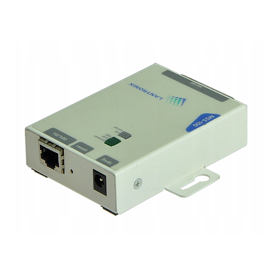
Page 13: Installation Procedure
Installation Procedure Installation Five LEDs are located on the top of the unit. The following table explains their functions. Table 2-1: MSS LEDs Function Power Glows green when power is supplied to the MSS Link Glows green while the MSS is connected properly to a 10BASE-T or 100BASE-T Ethernet network Glows green to indicate a 100BASE-T Ethernet connection Blinks yellow, green, or red to indicate MSS activity. - Page 14 Installation Installation Procedure The following diagram shows a properly-installed MSS. The numbers in the diagram refer to the installation steps in this section. Figure 2-4: MSS Connected to Serial Device and Ethernet Serial Device 10/100BASE-T Ethernet Select a location. The MSS should be positioned close to the device it will be servicing. Since power- ing down the unit will terminate any active sessions, it may be desirable to place the server in a location secure from user access.
- Page 15 Installation Procedure Installation Connect one end of the power cable to the MSS power jack. Connect the power cube end of the power cable to a standard wall outlet. When the MSS receives power, it begins a three-step boot process. The MSS runs through a set of power-up diagnostics for approximately five seconds.
-
Page 16: 3: Getting Started
3: Getting Started This chapter covers all of the steps needed to get the MSS on-line and working. There are three basic methods used to log into the MSS and begin configuration. Incoming (Remote) Logins: EZWebCon is the preferred configuration method. Users can also use the internal HTTP server via a standard web browser. -
Page 17: Ip Address Configuration
IP Address Configuration Getting Started If another user is currently the privileged user for the MSS, use the Set Privileged Override command to forcibly become the privileged user. To relinquish privileged status, enter the Set Noprivilege command. The privileged password can be changed with the Change Privpass command. Specify a new password of up to six alphanumeric characters. -
Page 18: Using Arp And Ping
Getting Started IP Address Configuration 3.2.2 Using ARP and Ping The ARP/ping method is available under UNIX and Windows. If the MSS has no IP address, it will set its address from the first directed IP packet it receives. On a UNIX host, create an entry in the host’s ARP table and substitute the intended IP address and the hardware address of the server, then ping the server (see Figure 3-3). -
Page 19: Using A Dhcp, Bootp, Or Rarp Reply
Change IPaddress command to make the address permanent. Figure 3-5: Changing the IP Address % telnet 192.0.1.228 Trying 192.0.1.228 Lantronix Version n.n/n (yymmdd) Type Help at the ‘Local_>’ prompt for assistance. Username> gopher Local> SET PRIVILEGED Password> system (not echoed) Local>>... -
Page 20: Incoming Logins
Location field. Figure 3-7: Sample Web Browser Login Once you have connected to the MSS, you will see the Lantronix ThinWeb Manager interface. Use the left-hand menu to navigate to subpages where you can configure important settings as well as view statistics and other server information. -
Page 21: Incoming Lat Logins
Incoming Logins Getting Started 3.3.1.2 EZWebCon Login and Configuration EZWebCon enables users on TCP/IP networks to log into and configure the MSS. The program offers a simple interface that prompts the user for the information necessary to configure the server. Instructions for installing, running, and using EZWebCon are included on the CD-ROM. -
Page 22: Remote Console Logins
Trying 192.0.1.88 Connected to 192.0.1.88 Escape character is ‘^]’ # access (not echoed) Lantronix MSS Version n.n/n (yymmdd) Type Help at the ‘Local>’ prompt for assistance. Enter Username> jerry 3.3.4.1 Changing the Login Password The login password is required for remote console logins and when the MSS password protection feature is enabled. -
Page 23: Logout
Logout Getting Started 3.5 Logout To manually log out of the MSS, type Logout or Logout Port at the Local> prompt or press Ctrl-D. Figure 3-15: Logging out of the MSS Local> LOGOUT... -
Page 24: 4: Configuration
4: Configuration Certain parameters must be configured before the MSS can function in the network. Although many users will prefer to use either the web browser interface or the EZWebCon graphical user interface, this chapter explains how to configure the MSS via the command line interface. -
Page 25: Protocol Configuration
Protocol Configuration Configuration If you are connecting from the network to the MSS serial port, enter the Change Password Incoming command at the Local> prompt. 4.2 Protocol Configuration Certain options can be configured for each of the protocols supported by the MSS. For more information on protocol configuration, refer to the Device Server Reference Manual. - Page 26 Configuration Protocol Configuration The MSS can be told which hosts are the gateways for the local network. If no gateway is specified, the MSS will listen to network broadcasts to decide which hosts are acting as gateways. The command below tells the MSS which host is the preferred gateway. Figure 4-3: Specifying a Gateway Local>>...
-
Page 27: Ipx (Netware) Configuration
Protocol Configuration Configuration 4.2.1.5 IP Security IP security allows the system administrator to restrict incoming and outgoing TCP/IP sessions and access to the serial port. Connections are allowed or denied based upon the source IP address (for incoming connections) or the destination IP address (for outgoing connections). - Page 28 Initialize Reload command is entered. If the software loadfile or loadhost address changes, you will have to change the configured parameters for the next reboot. For the following example, the loadhost is phred, and the name of the loadfile is “MSS100.SYS”. Figure 4-9: Changing the NetWare Loadhost Local_2>>...
-
Page 29: Lat Configuration
Protocol Configuration Configuration 4.2.3 LAT Configuration Three LAT parameters can be configured for the MSS: the server’s identification string, its service group list, and its internal circuit timer. 4.2.3.1 Server Identification The MSS has a default name that it uses when announcing itself to the LAT network (mss_xxxxxx where xxxxxx represents the last six characters of its hardware address). -
Page 30: Serial Port Configuration
Configuration Serial Port Configuration 4.3 Serial Port Configuration The serial port is set at the factory for 9600 baud, 8 data bits, one stop bit, and no parity. Remember that the port should be logged out after configuration so the changes will go into effect. -
Page 31: Baud Rate
Serial Port Configuration Configuration 4.3.3 Baud Rate The MSS and the attached serial device must agree on a speed, or baud rate, to use for the serial connection. Valid baud rates for the MSS are 300, 600, 1200, 2400, 4800, 9600 (the default), 19200, 38400, 57600, 115200, and 230400 baud. -
Page 32: Modems And Modem Signaling
Configuration Serial Port Configuration To switch between flow control methods, use the Change Flow Control command followed by the preferred method. If you do not wish to use flow control at all, specify None. Figure 4-19: Enabling Recommended Flow Control Local>>... - Page 33 Serial Port Configuration Configuration 4.3.6.2 Signal Checking When signal checking is enabled, the MSS will check for the presence of an asserted Data Signal Ready (DSR) input signal before allowing incoming network connections to the serial port. Network connections to the serial port will not be permitted unless the DSR signal is asserted.
-
Page 34: Logouts
Configuration Serial Port Configuration 4.3.7 Logouts In addition to DSRLogouts, the port can be manually logged out, or it can be configured to automatically log out when it has been inactive for a pre-determined length of time. To manually log out of the MSS, type Logout at the Local> prompt, or press Ctrl-D. Figure 4-24: Logging out of the MSS Local>>... -
Page 36: 5: Using The Mss
Making the MSS look like a modem so that it can be used with existing communications software (see Modem Emulation Mode on page 5-9). Using the Lantronix COM Port Redirector software to redirect PC COM ports (see COM Port Redirector on page 5-11). -
Page 37: Host Applications
Interactive Connections Using the MSS There are some important points to remember when making a socket connection: Port access must be set to either Dynamic or Remote to allow network connection requests. Local access does not allow a port to receive connection requests from the network. -
Page 38: Outgoing Connections
Using the MSS Interactive Connections 5.2.1 Outgoing Connections The MSS can make outgoing connections to hosts on TCP/IP networks via its serial port. It supports Telnet and Rlogin connections, and environment strings added to the connection commands. See the Command Reference chapter of the Device Server Reference Manual on the CD-ROM for more information. - Page 39 Interactive Connections Using the MSS 5.2.2.1 Break Key and Local Switch The Break key allows users to leave an active session and return to the MSS Local> prompt without disconnecting sessions. By default, the MSS handles the Break key locally. Users can change whether the Break key is processed by the MSS (Local), processed by the remote host (Remote), or ignored (None) using the Change Break command.
-
Page 40: Status Displays
Using the MSS Interactive Connections The Change Backward Switch and Change Forward Switch commands define keys used to switch sessions without returning to local mode. Backward and forward switch keys must be explicitly defined. Figure 5-5: Defining Switches Local>> CHANGE BACKWARD SWITCH ^B Local>>... - Page 41 Interactive Connections Using the MSS 5.2.3.3 Show Ports Show Ports displays the configuration and connection status of the serial port—settings such as flow control, baud rate, parity, and default hosts. In addition, it shows the status of DSR and DTR serial signals, port access type, and login status. Errors are summarized, although in less detail than in the Show Server Counters display.
-
Page 42: Serial Tunnel
Using the MSS Serial Tunnel 5.3 Serial Tunnel Two MSS servers can be connected to emulate a direct serial connection across a LAN or WAN. Servers connected in this way can pass data only—they will not be able to pass status signals (DSR/DTR, CTS/RTS, etc.) or preserve timing between characters. -
Page 43: Multihost Mode
Multihost Mode Using the MSS MSS_B (192.168.5.10) Local>> CHANGE DEDICATED TCP 192.168.5.2:4096U Local>> CHANGE AUTOSTART ENABLED Local>> CHANGE ACCESS DYNAMIC Setting up Dedicated hosts ensures that the units will always talk only to each other. Enabling Autostart for both units enables one MSS to send data to the other MSS without having to wait for a serial carriage return to start the session.. -
Page 44: Adding Hosts
Using the MSS Modem Emulation Mode When you enable a dedicated connection, the MSS disables local mode hotkeys for session manipulation. 5.4.2 Adding Hosts The host list can include up to 12 host entries in any combination of TCP (raw, Telnet, and Rlogin) and UDP addresses. -
Page 45: Modem Mode Commands
Modem Emulation Mode Using the MSS To use modem mode, enable modem emulation and set your MSS for Autostart using A as the autostart character. This triggers the MSS to enter modem mode whenever it sees a modem-style AT command. Figure 5-10: Enabling Modem Mode Local>>... -
Page 46: Wiring Requirements
5.6 COM Port Redirector The Lantronix Com Port Redirector application allows PCs to share modems and other serial devices connected to an MSS using Microsoft Windows applications. The Redirector intercepts communications to specified PC COM ports and sends them over a network connection to the MSS serial port. -
Page 48: A: Contact Information
If you are experiencing an error that is not listed in Appendix B or if you are unable to fix the error, contact your dealer or Lantronix Technical Support at 800-422-7044 (US) or 949- 453-3990. Technical Support is also available via Internet email at support@lantronix.com. -
Page 50: B: Troubleshooting
This Appendix discusses how to diagnose and fix errors quickly yourself without having to contact a dealer or Lantronix. It will help to connect a terminal to the serial port while diagnosing an error to view any summary messages that are displayed. -
Page 51: Dhcp Troubleshooting
DHCP Troubleshooting Troubleshooting Table B-1: Power-up Problems and Error Messages, cont. Problem/Message Error Remedy The terminal shows a The MSS is not connected Ensure that the MSS is firmly connected Boot> prompt rather properly to the Ethernet. to a functional and properly-terminated than a Local>... -
Page 52: Bootp Troubleshooting
Troubleshooting BOOTP Troubleshooting B.3 BOOTP Troubleshooting If the BOOTP request is failing and you have configured your host to respond to the request, check these areas: Table B-3: BOOTP Troubleshooting Area to Check Explanation BOOTP is in your system’s BOOTP must be an uncommented line in /etc/services. /etc/services file. -
Page 53: Modem Configuration Checklist
Modem Configuration Checklist Troubleshooting B.5 Modem Configuration Checklist Most modem problems are caused by cabling mistakes or incorrect modem configuration. However, the following items should be verified after any modem configuration, and re- checked when there is modem trouble. The modem must be configured to disconnect immediately when DTR is de- asserted. - Page 54 These commands set the Server’s address, the software loadfile, and the loadhost’s IP address (as well as that of a backup loadhost). The server then reboots using the Flash command and will attempt to load the file MSS100.SYS from the host at 192.0.1.188. Flush NVR This command is used to restore the MSS’s...
- Page 55 BCP Command Examples Troubleshooting server will attempt to reload continuously. If there is an error, or if the console’s Return key is pressed, the MSS will re-enter the Boot Configuration Program. Change BOOTP {Enabled, Disabled} Enables or disables the sending of BOOTP queries during the boot sequence.
- Page 56 Troubleshooting BCP Command Examples Change Software filename Specifies the name of the file to load. The MSS will automatically add .SYS to the filename you specify. Note that all protocols must have a filename specified (either the default or set by the user).
-
Page 58: C: Pinouts
C: Pinouts In the following diagrams, unlabeled pins are not connected. C.1 Ethernet Connector The MSS uses a standard Ethernet pinout. The figure below shows the MSS RJ45 Ethernet connector pin connections. Figure C-1: RJ45 Ethernet Connector 1 2 3 4 5 6 7 8 C.2 MSS Serial Connector C.2.1 DB25 Connector The figure below shows the pin connections of the MSS DB25 connector. - Page 59 Modem Wiring Pinouts C.2.2 Modem Wiring C.2.2.1 DSR (Data Signal Ready) versus CD (Carrier Detect) By default, most modems assert CD only during a valid connection. In this case the modem’s CD pin may be wired to the Server’s DSR pin. Alternately, many modems can be configured such that DSR acts like CD.
-
Page 60: D: Updating Software
D: Updating Software D.1 Obtaining Software A current software file (MSS100.SYS) is available on the distribution CD. You can obtain software updates and release notes for the MSS from the Lantronix World Wide Web site (www.lantronix.com), or by using anonymous FTP through the Internet (ftp.lantronix.com). -
Page 61: Reloading Software
NetWare, TCP/IP, or MOP. Regardless of which protocol is used to update Flash ROM, the following points are important: The Flash ROM software file name, MSS100.SYS, should not be changed. The download file should be world-readable on the host. - Page 62 Commands chapter of the Device Server Reference Manual located on the CD-ROM. D.2.1.2 NetWare The MSS100.SYS file should be placed in the login directory on the NetWare file server. The MSS cannot actually log into the file server (since it knows no username/password); it can only access files in the login directory itself.
-
Page 63: Troubleshooting Flash Rom Updates
Ensure that TFTP is enabled on the host; several major UNIX vendors ship their systems with TFTP disabled by default. Ensure that the Ethernet circuit must has the service characteristic enabled. Ensure that the MOM$LOAD search path includes the directory containing the MSS100.SYS file. -
Page 64: E: Specifications
E: Specifications E.1 Power Specifications The MSS power cube adaptor has the following specifications: Adapter input voltage: 110 VAC US, 220 VAC International Adapter output voltage: 5 VDC at 700 mA Operating current: 700 mA @ 5 V Power consumption: 4.2 Watts maximum E.2 Environmental Information E.2.1 Temperature Limitations... - Page 65 Environmental Information Specifications E.2.3 Altitude Limitations Operating: 2.4 km (8,000 ft) Storage: 9.1 km (30,000 ft) When operating the MSS above 2.4 km (8,000 ft), decrease the operating temperature rating by 1.8˚C for each 1,000 m (1˚F for each 1,000 ft).
-
Page 66: Warranty Statement
Warranty Statement Lantronix warrants for a period of 5 YEARS years from the date of shipment that each MSS100 Device Server supplied shall be free from defects in material and workmanship. During this period, if the customer experiences difficulties with a product and is unable to resolve the problem by phone with Lantronix Technical Support, a Return Material Authorization (RMA) will be issued. -
Page 67: Declaration Of Conformity
Characteristics of Information TechnologyEquipment. The product complies with the requirements of the Low Voltage Directive 72/23/EEC and the EMC Directive 89/336/ EEC. Manufacturer’s Contact: Director of Quality Assurance, Lantronix 15353 Barranca Parkway, Irvine, CA 92618 USA General Tel: 949/453-3990 Fax: 949/453-3995... -
Page 68: Index
Index DSR (Data Signal Ready) 4-7, 4-10, Access mode 4-7 DSRLogout 4-10 Altitude limitations E-2 DTR (Data Transmit Ready) 4-10, ARP entry 3-3 Autobaud 4-8, B-4 DTRWait 4-10 Autostart 4-7 Encapsulation 4-4 BCP (Boot Configuration Program) Ethernet 3-6, B-5 Address B-6 Boot prompt 3-6, B-1, B-4 Ethernet connector C-1 BOOTP 1-1, 2-4, 3-4, D-2... - Page 69 Encapsulation 4-4 Reloading software D-3 Loadhost 4-5 Node 4-5 Routing 4-4, 4-5 Nameserver 1-1, 4-3 NetWare 1-3 Reloading software D-3 Lantronix Node 1-3 Contact information A-1 NVRAM B-5 Technical support A-1 LAT 3-6, 4-6 Circuit timer 4-6 OK LED 2-4...
- Page 70 Ping 3-3 Restoring defaults B-5 Pinouts C-1 RJ45 2-1, C-1 Port 7000 3-7 Rlogin 1-1, 3-6 Ports Routing, NetWare 4-4 Access 4-7 RTS/CTS 4-8 Character size 4-8 Dedicated service 4-11 Flow control 4-8 SDK 1-2 Local prompt 4-11 Security 1-2 Logout 4-11 Serial Modem control 4-7...
- Page 71 TCP/IP 3-5, 4-2, B-1 Reloading software D-2 Support information 1-1 Telnet 1-1, 3-6 Temperature limitations E-1 TFTP D-2 ThinWeb Manager 1-1, 3-5 Troubleshooting B-1–B-7 BOOTP B-3 DHCP B-2 Flash (software) updates D-4 Modems B-4 Power-up B-1 RARP B-3 Tunnel, serial 5-7 UDP 1-2, 5-7 Updating software D-1 Web browser interface 1-1, 3-5...
Need help?
Do you have a question about the MSS100 and is the answer not in the manual?
Questions and answers